 English
 Le français
 Türkçe





A star-delta power circuit is the main current path between the supply and the motor: a Q1 protective device, a K1 main contactor, a K2 star contactor, a K3 delta contactor and an F2 overload relay. At start-up K1 and K2 close, so the windings are connected in star; once the motor has run up, K2 drops out, K3 closes and the motor keeps running in delta. This article reads the diagram the way the current flows through it.
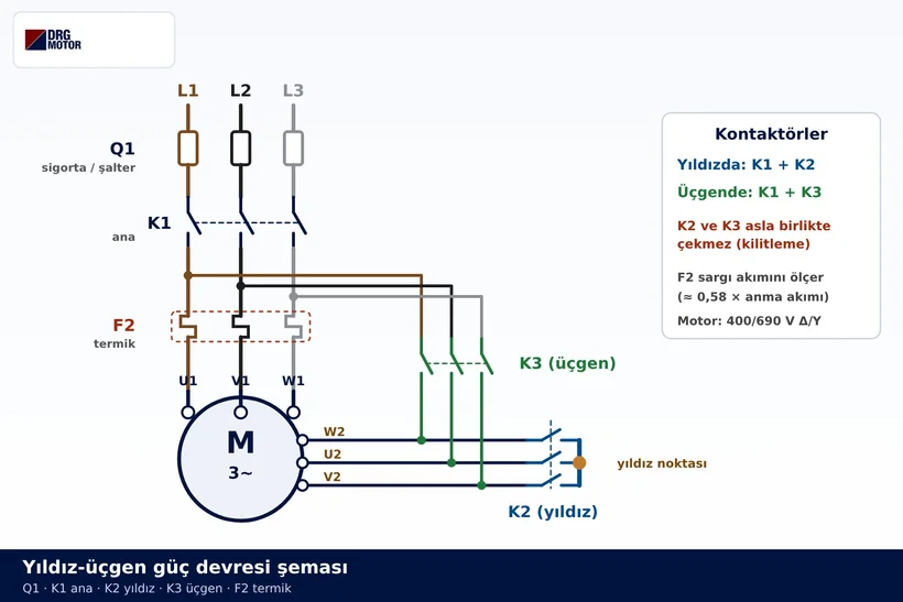
The control side (start and stop buttons, timer, interlocking) is a separate topic, covered in our star-delta control circuit article. Here we stay with the main contacts, the part of the panel that actually carries motor current.
Which components make up the power circuit?
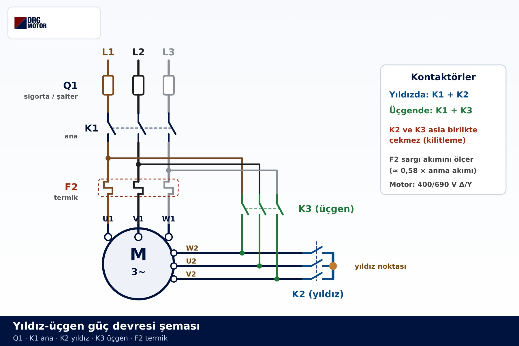
At the top of the drawing are the three phases L1, L2 and L3. They first pass through Q1, which may be fuses or a motor protection circuit breaker and protects the line against short circuits. Next comes the K1 main contactor. Downstream of K1 the circuit splits into two branches: one goes through the F2 overload relay to the upper row of motor terminals (U1, V1, W1), the other feeds the K3 delta contactor. The lower row of terminals (W2, U2, V2) is wired both to K3 and to the K2 star contactor, whose outgoing side is shorted together to form the star point.
| Component | Function | Active during |
|---|---|---|
| Q1 (fuses / breaker) | Short-circuit protection and isolation | Always in circuit |
| K1 main contactor | Connects U1-V1-W1 to the supply | Star and delta |
| K2 star contactor | Joins W2-U2-V2 into a star point | Start-up only |
| K3 delta contactor | Connects W2-U2-V2 to the phases | Running only |
| F2 overload relay | Opens the control circuit on overload | Star and delta |
Notice that there are no links in the motor terminal box. All six winding ends are brought out to the panel, and the contactors do the job that the links would otherwise do. The linked version itself is explained in 3-phase motor wiring diagram and terminal links.
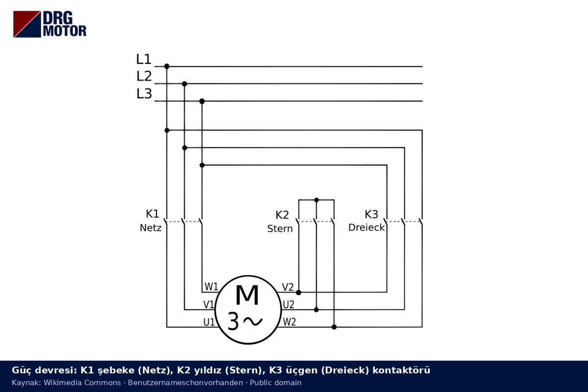
The drawing below shows the same circuit in a simpler form. German labels: Netz = line (K1), Stern = star (K2), Dreieck = delta (K3).
Star stage: where does the current flow?
When start is pressed, K1 and K2 close while K3 stays open. The path for phase L1 is: L1 → Q1 → K1 → F2 → U1 → first winding → U2 → K2. The same happens for L2 through V1–V2 and for L3 through W1–W2. Because the three lower ends meet inside K2, the windings are in star.
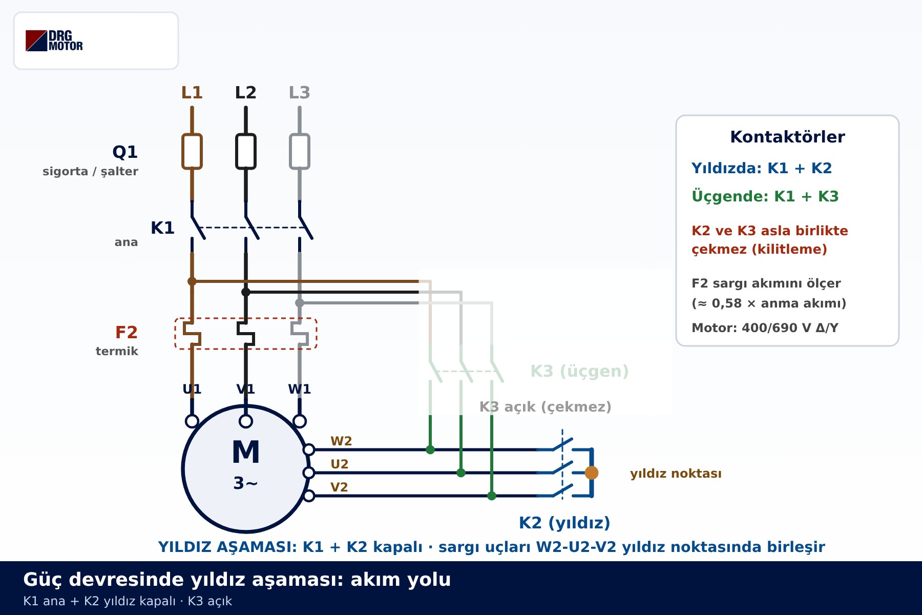
In this stage each winding sees the line voltage divided by √3, roughly 230 V on a 400 V supply. With the winding voltage reduced by √3, the same motor on the same supply draws about one third of the line current it would take in a direct delta start, and its starting torque also falls to about one third. The star stage is therefore a short transition while the motor accelerates under light load. The underlying voltage and current relationships are explained in what is a star-delta connection.
Click to see current electric motor prices and order nowSEE PRICES →
Delta stage: where does the current flow?
Once the motor is up to speed, the control circuit releases K2 and, after a brief pause, energises K3. K1 stays closed. Each phase is now connected to two terminals: L1 to U1 (through K1 and F2) and to W2 (through K3), L2 to V1 and U2, L3 to W1 and V2. This is exactly the U1–W2, V1–U2, W1–V2 delta link pattern of the terminal box, made by a contactor instead of metal links.
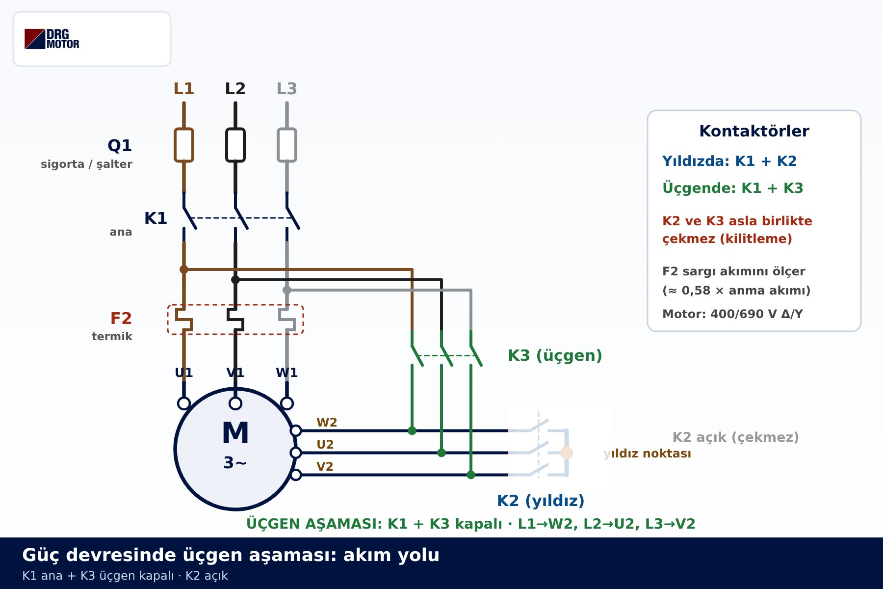
In delta every winding sees the full line voltage of 400 V. A motor used with a star-delta starter must therefore be rated for 400 V in delta; in the DRG range that means the 400/690 V Δ/Y motors from 4 kW upwards. The 230/400 V Δ/Y motors up to 3 kW run in star on a 400 V supply; switching them to delta would overvolt the windings, so they are not suitable for star-delta starting. For more on this split, see which kW motor is connected in star or delta.
Contactor state table
The quickest way to read a star-delta power circuit is a table showing which contactor is closed at each step:
| Step | K1 | K2 | K3 |
|---|---|---|---|
| Stopped | Open | Open | Open |
| Star (start-up) | Closed | Closed | Open |
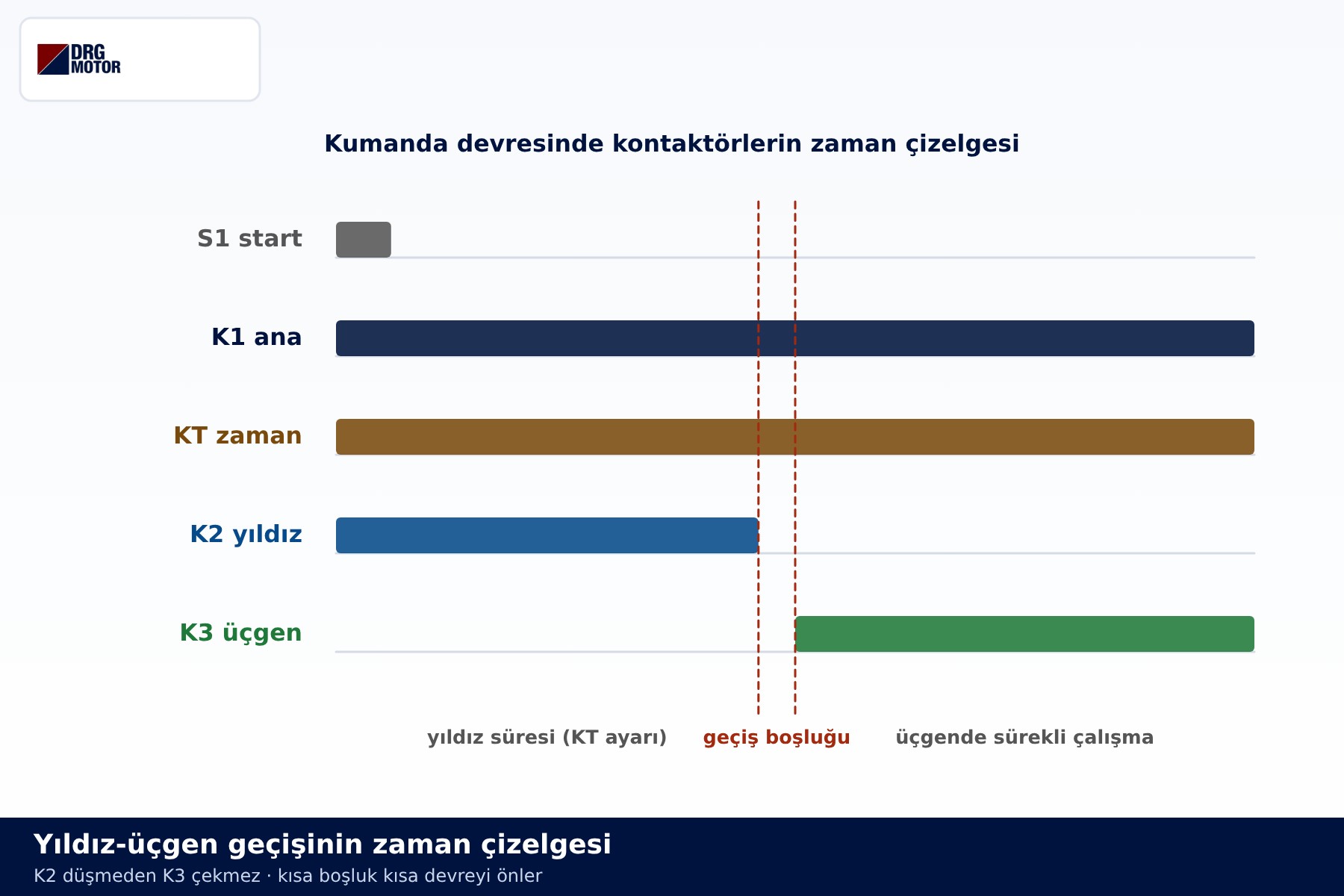
| Changeover gap | Closed | Open | Open |
| Delta (running) | Closed | Open | Closed |
In no row are K2 and K3 closed together. If both were energised, K3 would feed the phases to W2-U2-V2 while K2 shorted those same terminals together, producing a phase-to-phase short circuit. That is why the control circuit interlocks K2 and K3 and leaves a short gap at changeover.
How much current does each contactor carry?
A less obvious feature of the star-delta power circuit is that all three contactors carry less than the motor's rated current (In). In delta, line current is √3 times the winding current. K1 feeds only the U1-V1-W1 branch and K3 only the W2-U2-V2 branch, so each carries one winding current: about In/√3, or 0.58 In. K2 carries current only during the star stage; since star current is one third of the delta value, the reference for K2 is roughly In/3.
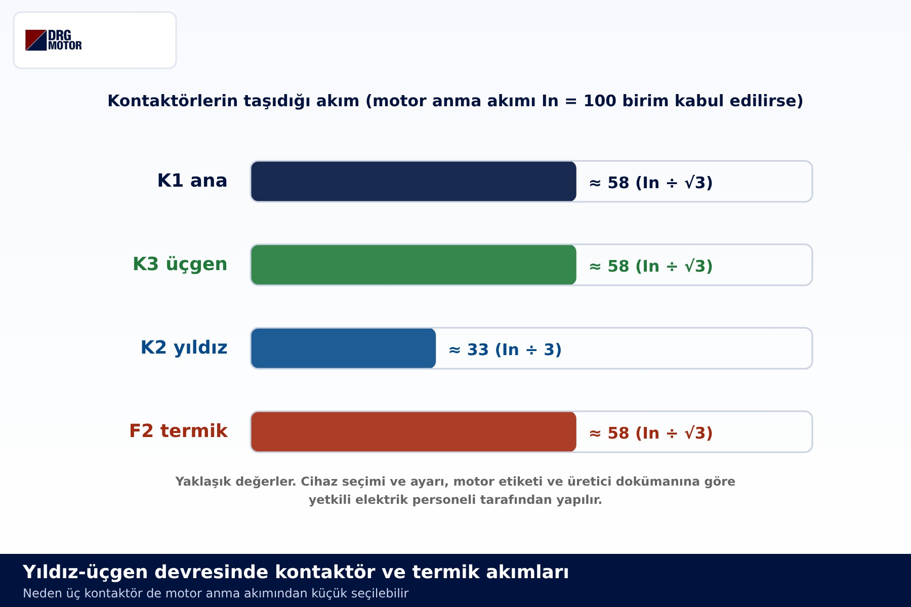
These ratios explain how the circuit works; they are not a device selection. The actual choice depends on run-up time, load type and the utilisation category given by the device manufacturer. For a worked example, see 22 kW motor star-delta starting.
Why is the overload relay placed after K1?
In the diagram, F2 sits between the output of K1 and terminals U1-V1-W1. In that position it measures current at the same point in both stages: in star the line current equals the winding current anyway, and in delta the current in the K1 branch is the current of one winding. The overload relay therefore protects the windings directly in both connections, and the value it sees is in the order of 0.58 times the motor's rated current.
If the overload relay were placed in the supply line, before the branch point, it would measure line current, which calls for a different setting logic. Which arrangement is used, and how the overload relay and timer are set, depends on the motor nameplate, the device manufacturer's documentation and the judgement of qualified electrical staff. The diagrams here explain the concept; building and commissioning the panel is a job for a qualified electrician.
Phase sequence and direction of rotation
In the delta stage, L1 goes to W2, L2 to U2 and L3 to V2 for a reason: this pairing keeps the rotating field turning the same way as it changes over from star to delta. If the lower terminals are mixed up, the motor is forced to produce torque against its own direction at the moment of changeover, causing a sharp current surge and mechanical stress. The first thing to check on any power circuit drawing is that the K3 outputs reach the motor terminals in this order.
You can see how starting current changes over time, including the brief peak at changeover, in our main guide, electric motor star-delta connection diagram. How the method compares with alternatives is covered in star-delta vs soft starter.
Quick checklist for reading the diagram on site
- Does the nameplate give 400 V as the delta value (400/690 V Δ/Y)?
- Have the links been removed from the terminal box, with all six ends taken to the panel?
- Does K1 feed U1-V1-W1 through F2, and K3 feed W2-U2-V2?
- Are the K2 outputs joined together?
- Are K2 and K3 electrically interlocked, and mechanically as well where required?
All the diagrams are collected in a single file: see the star-delta wiring diagram PDF guide or open the PDF directly. For the terminal box side, motor terminal star-delta connection is a useful companion.
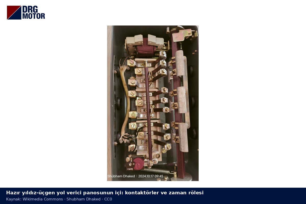
On site, this circuit is usually built into a ready star-delta panel. The photo shows how the three contactors and the timer sit inside the enclosure.
DRG motors suitable for star-delta starting
DRG Motor is an electric motor manufacturer, supplier and seller. The models below have 400/690 V Δ/Y windings; they run in delta on a 400 V supply and are therefore suitable for star-delta starting. Contactors, overload relays and timers are not sold by DRG; please source them from your switchgear supplier. The full range is listed on the three-phase asynchronous electric motors page and in the online shop.
- DRG-132M-4 – 7.5 kW – 1500 rpm class – aluminium frame
- DRG-160M-4 – 11 kW – 1500 rpm class – aluminium frame
- DRG-160L-4 – 15 kW – 1500 rpm class – cast iron frame
- DRG-180M-4 – 18.5 kW – 1500 rpm class – cast iron frame
- DRG-180L-4 – 22 kW – 1500 rpm class – cast iron frame
Click to see current prices for these motors and order nowSEE PRICES →
Frequently asked questions
How many contactors does a star-delta power circuit use?
Three: K1 main, K2 star and K3 delta. K1 is closed in both stages; K2 closes only during start-up and K3 only during running.
What happens if K2 and K3 close at the same time?
K3 feeds the phases to the lower motor terminals while K2 joins those terminals together, so a phase-to-phase short circuit occurs and Q1 trips. Interlocking between the two contactors is essential.
Why can the contactors be smaller than the motor's rated current?
K1 and K3 each carry one winding current, about 0.58 In, and K2 carries roughly In/3 during the star stage only. The final choice follows the device manufacturer's data.
Why does the overload relay measure winding current rather than line current?
F2 is connected after K1 and after the branch point, so it only sees the U1-V1-W1 branch. In both star and delta, that branch carries the current of a single winding.





