 English
 Le français
 Türkçe




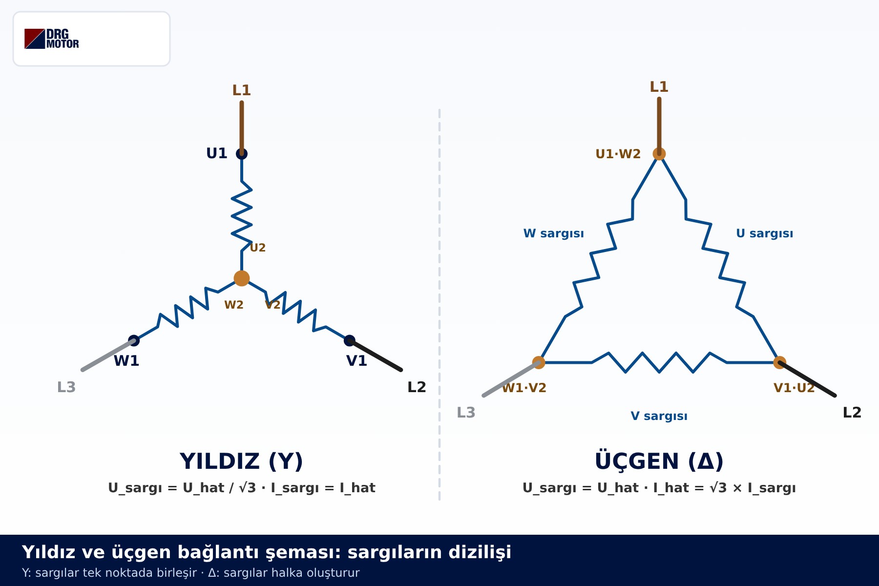

An electric motor star-delta connection diagram shows the two ways the three windings of a three-phase induction motor can be connected to the supply. In star, one end of each winding meets at a common point and each winding receives the line voltage divided by √3; in delta, the windings form a closed loop and each one sees the full line voltage. A star-delta starter runs the motor up in star and then switches it to delta, which cuts the starting current and torque to roughly one third.
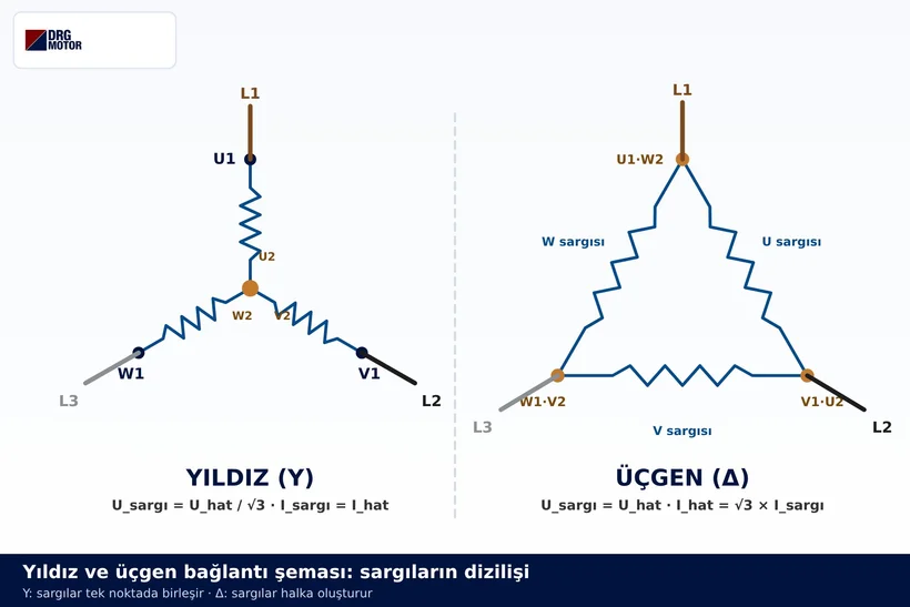
This guide walks through the diagrams one by one and explains what each line means: winding ends, terminal links, the power circuit, the control circuit, the current carried by each contactor and the shape of the starting current. If you only need the concept in short form, read what is a star-delta connection. All diagrams are also collected in the star-delta connection diagrams PDF.
What Do the Letters and Symbols in the Diagram Mean?
The same letters appear on the motor side and on the panel side of a star-delta diagram. Knowing what each one stands for makes it much easier to follow a line from one component to the next.
| Symbol | Meaning | Position in the diagram |
|---|---|---|
| L1, L2, L3 | The three supply phases (lines) | Top, supply side |
| U1, V1, W1 | Start ends of the three windings | Upper row of the terminal box |
| U2, V2, W2 | Finish ends of the same windings | Lower row, arranged W2 U2 V2 |
| Q1 | Short-circuit protection (fuses or motor circuit breaker) | Input of the power circuit |
| K1, K2, K3 | Main, star and delta contactors | Power and control circuits |
| F2 | Thermal overload relay | Between K1 output and the motor |
| KT | Timer | Control circuit |
People often ask why the lower row reads W2 U2 V2 rather than U2 V2 W2. The offset lets each delta link run straight up and down: U1 sits above W2, V1 above U2 and W1 above V2. How the links are placed on the terminal block is covered separately in 3-phase motor wiring diagram and terminal links.
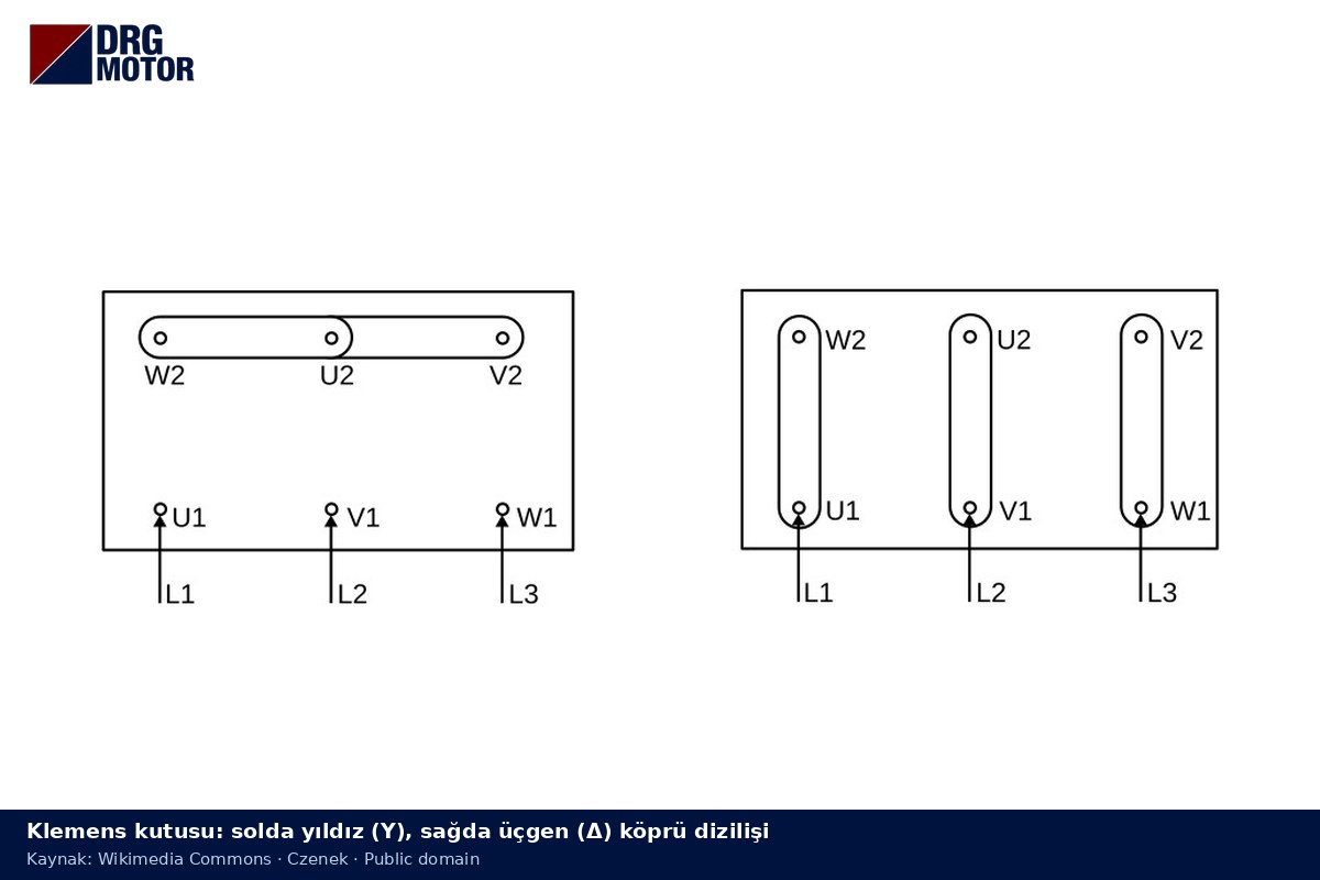
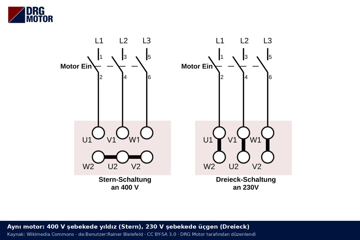
The terminal drawing above puts both layouts side by side: on the left a single link across the lower row gives star, on the right three vertical links give delta. Some images in this article carry German labels: Stern means star, Dreieck means delta and Netz means supply (line).
Star Connection Diagram: The Windings Meet at One Point
In a star (Y) connection the finish ends W2, U2 and V2 are joined together to form the star point. The start ends U1, V1 and W1 go to L1, L2 and L3 respectively. In the terminal box this appears as a single horizontal link across the three lower terminals.
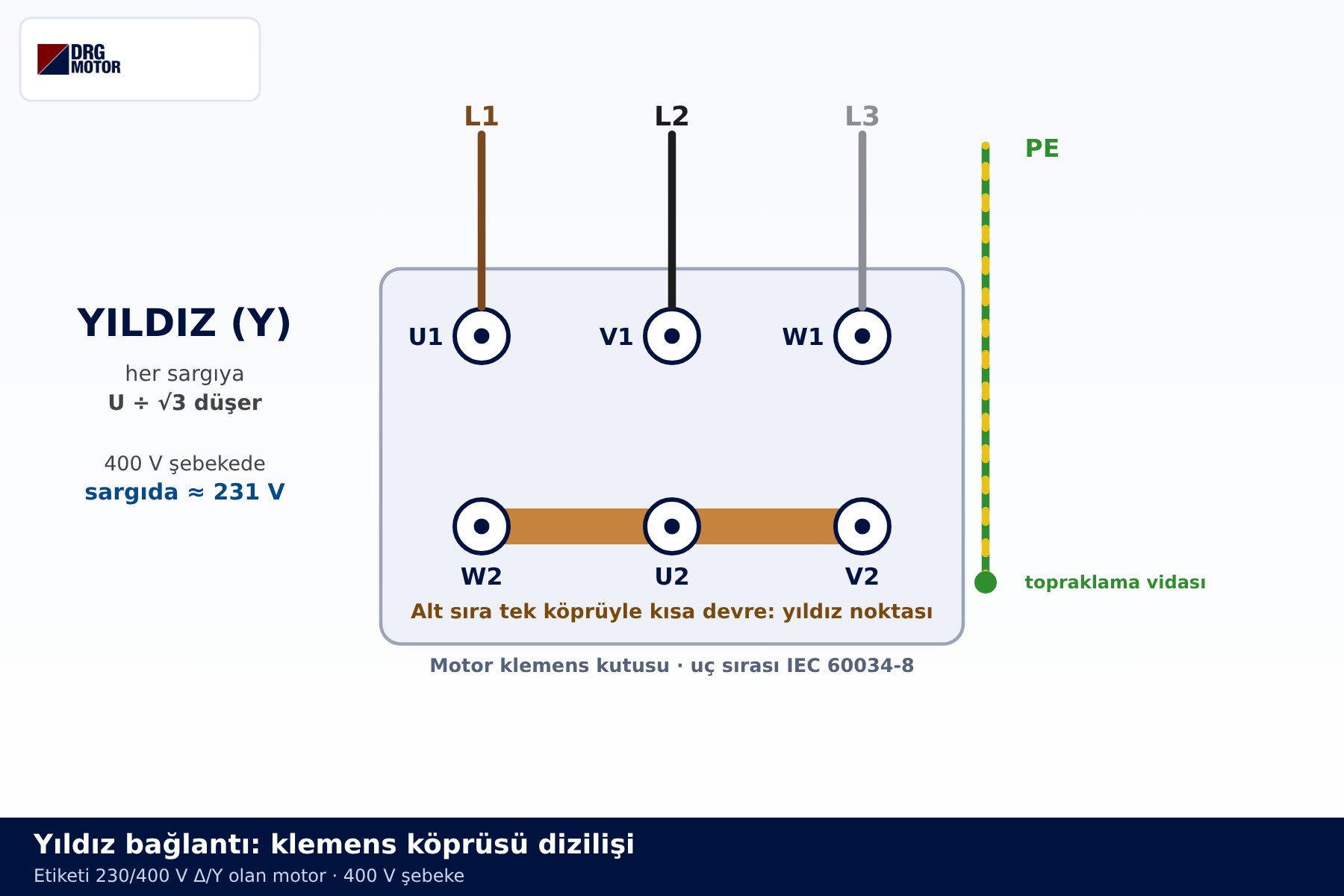
In star, each winding is connected between one phase and the star point rather than between two phases. The voltage across a winding is therefore the line voltage divided by √3 (≈1.732), about 231 V on a 400 V supply. The line current flows straight through the winding, so in star the line current equals the winding current.
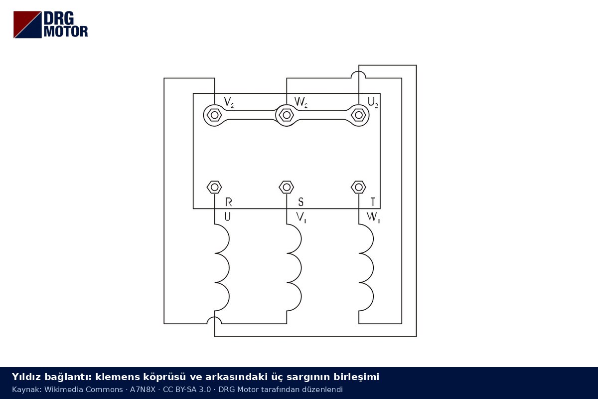
The star connection diagram is also used on its own: a motor rated 230/400 V Δ/Y runs in star on a 400 V supply. In a star-delta starter, however, star is only the starting stage; the motor accelerates in this connection for a few seconds and is then switched to delta.
Delta Connection Diagram: The Windings Form a Loop
In a delta (Δ) connection the end of each winding is joined to the start of the next, so the three windings form a closed loop. In the terminal box this is done with three vertical links: U1–W2, V1–U2 and W1–V2. The phases land on the corners of the loop: L1 → U1·W2, L2 → V1·U2, L3 → W1·V2.
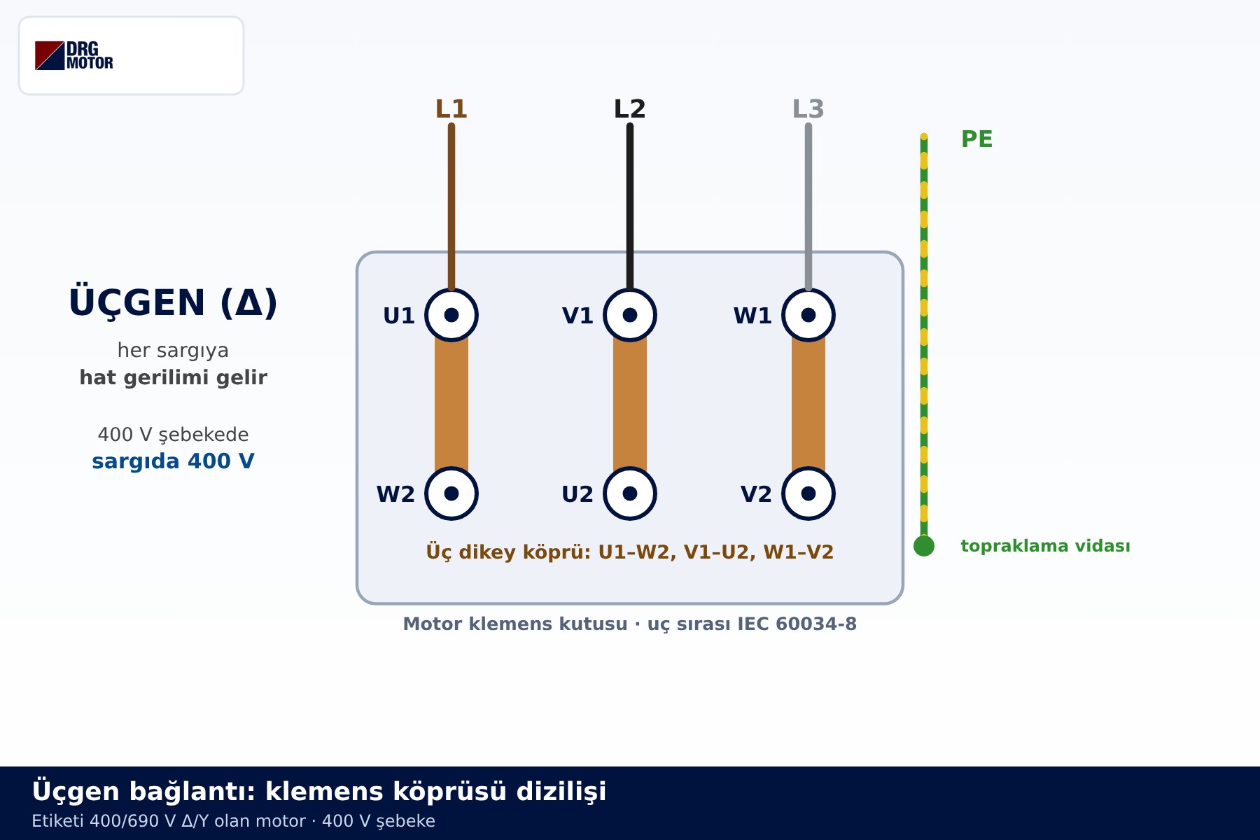
In delta every winding sits directly between two phases and sees the full line voltage, 400 V on a 400 V supply. The current arriving on one line conductor splits between two windings, so the line current is √3 times the winding current. This relation explains why, further on, the contactors carry less than the motor's rated current.
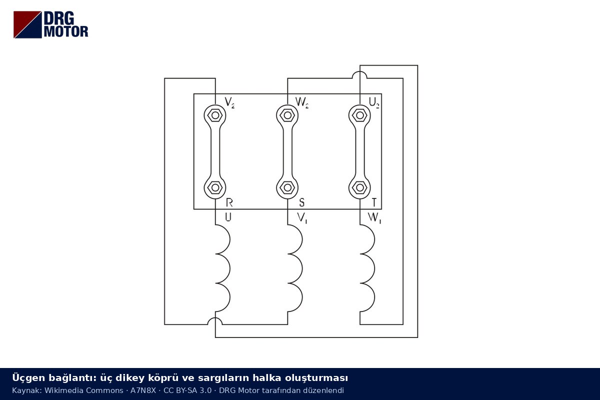
For how the links are moved from star to delta in the terminal box, see motor terminal star-delta connection. With a star-delta starter no links are fitted in the terminal box at all: all six ends are brought out to the panel and the contactors do the job of the links.
Click to see current electric motor prices and order nowSEE PRICES →
Voltage, Current and Power: The Formulas Under the Diagrams
The short formulas printed under star and delta diagrams express a single idea: the voltage across a winding sets the current through it and the torque the motor can produce.
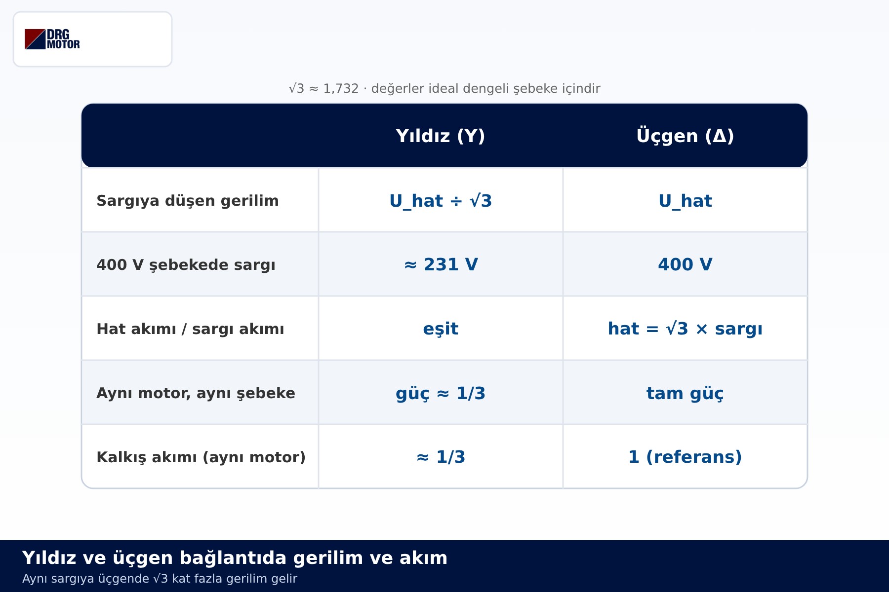
| Quantity | Star (Y) | Delta (Δ) |
|---|---|---|
| Winding voltage | U / √3 (≈231 V at 400 V) | U (400 V at 400 V) |
| Line current | Equal to winding current | √3 × winding current |
| Starting current (same motor, same supply) | ≈ 1/3 of delta | Direct-on-line value |
| Starting torque | ≈ 1/3 of delta | Full starting torque |
The one-third ratio comes from two effects. When the same motor on the same supply is switched to star, each winding receives √3 times less voltage, so the winding current also falls by √3. In delta the line current is √3 times the winding current, so the two factors multiply and the line current drops to about 1/3. Because torque varies with the square of voltage, the starting torque also falls to about 1/3. That is why star-delta starting suits machines that start lightly loaded (fans, pumps starting against low load, saws); a machine that starts under heavy load may not accelerate enough in star.
The Nameplate Tells You Which Diagram to Use
Before any diagram, the nameplate decides whether a motor is connected in star or delta. Its two voltage values show which connection suits which supply. The rule is simple: if the supply voltage matches the higher value, connect in star; if it matches the lower value, connect in delta.
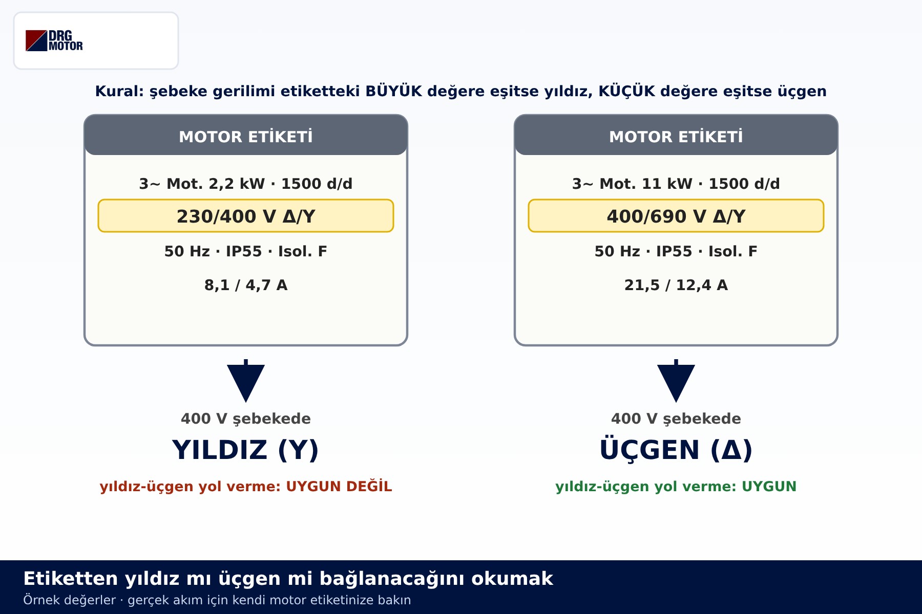
The next drawing shows the same rule at the terminal box for a motor rated 230/400 V: star (Stern-Schaltung) on a 400 V supply, delta (Dreieck-Schaltung) on a 230 V supply. In both cases each winding sees the same voltage, about 230 V.
DRG Motor is an electric motor manufacturer, supplier and seller. In the DRG range, motors up to 3 kW are wound for 230/400 V Δ/Y: on a 400 V supply they are connected in star and are not suitable for star-delta starting, since switching to delta would put 400 V across a 230 V winding. Motors of 4 kW and above are wound for 400/690 V Δ/Y: they run in delta on 400 V and can be started in star, so they are suitable for star-delta starting. The power threshold is discussed in which kW motor is star or delta connected.
Star-Delta Starter Power Circuit Diagram
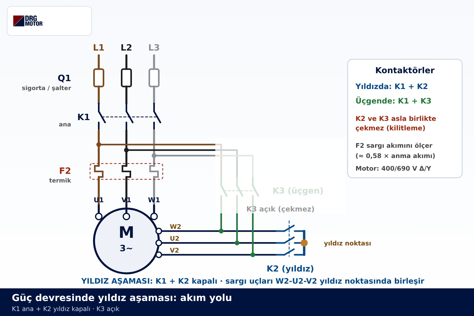
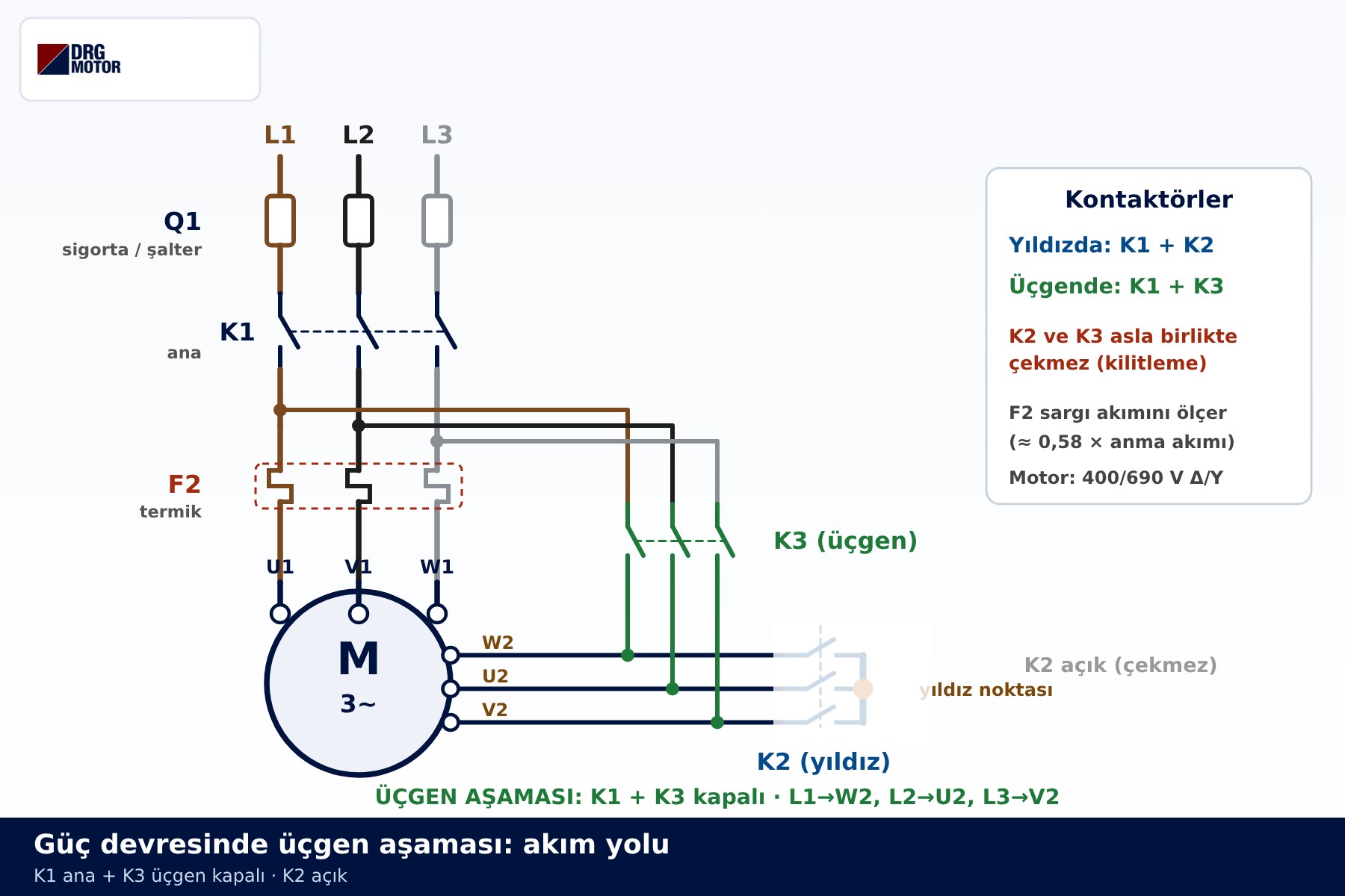
The power circuit shows the path the motor current takes from the supply to the windings. A classic star-delta power circuit contains short-circuit protection (Q1), three contactors (K1, K2, K3) and a thermal overload relay (F2).
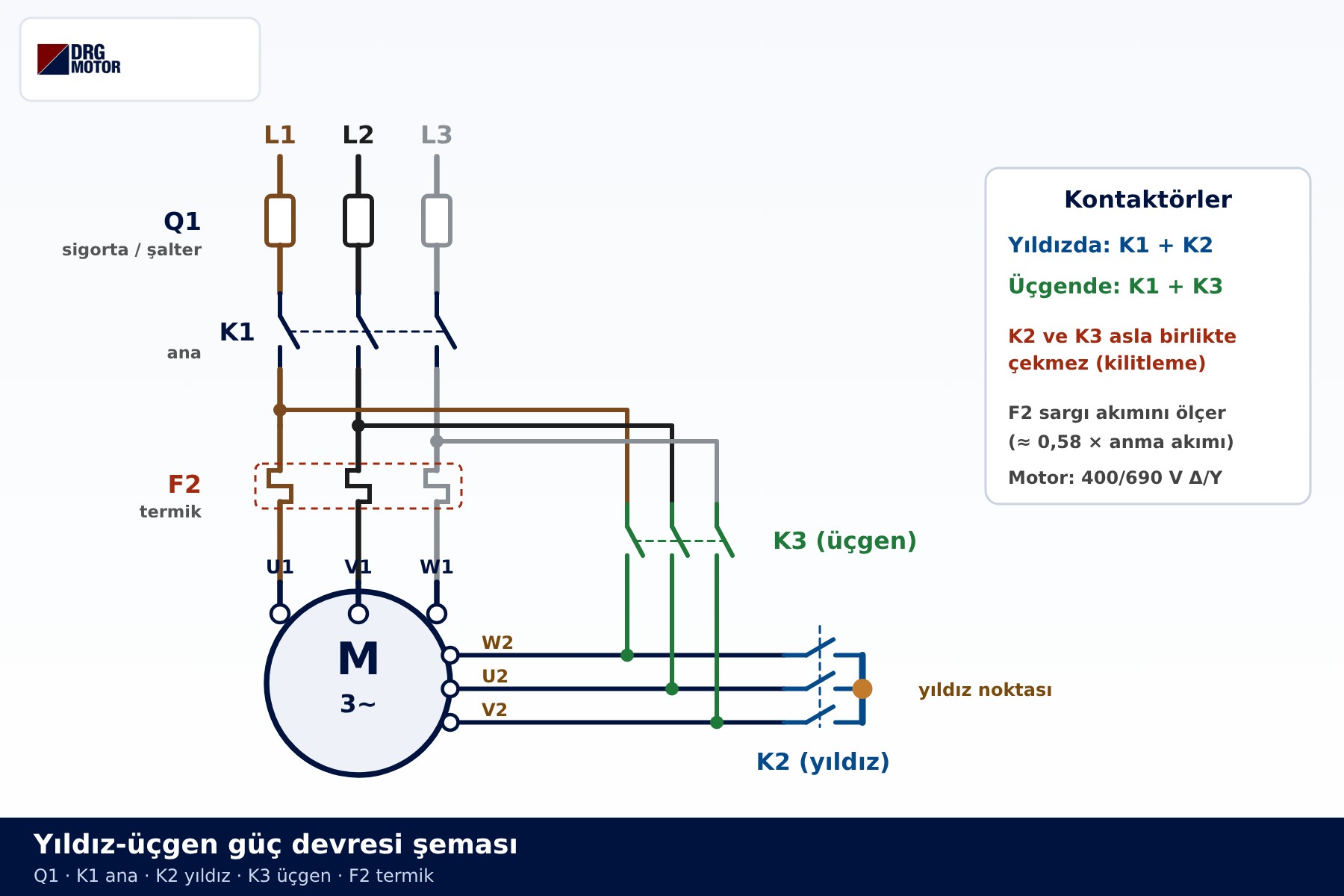
K1 is the main contactor: it feeds L1, L2 and L3 through the overload relay to U1, V1 and W1 and stays closed as long as the motor runs. K2 is the star contactor: it shorts W2, U2 and V2 together to create the star point. K3 is the delta contactor: it connects W2 to L1, U2 to L2 and V2 to L3, closing the loop.
The simplified drawing below shows only the three contactors, without protective devices. It makes it easy to see how the six winding ends are brought to the panel and how K2 joins three of them at a single point.
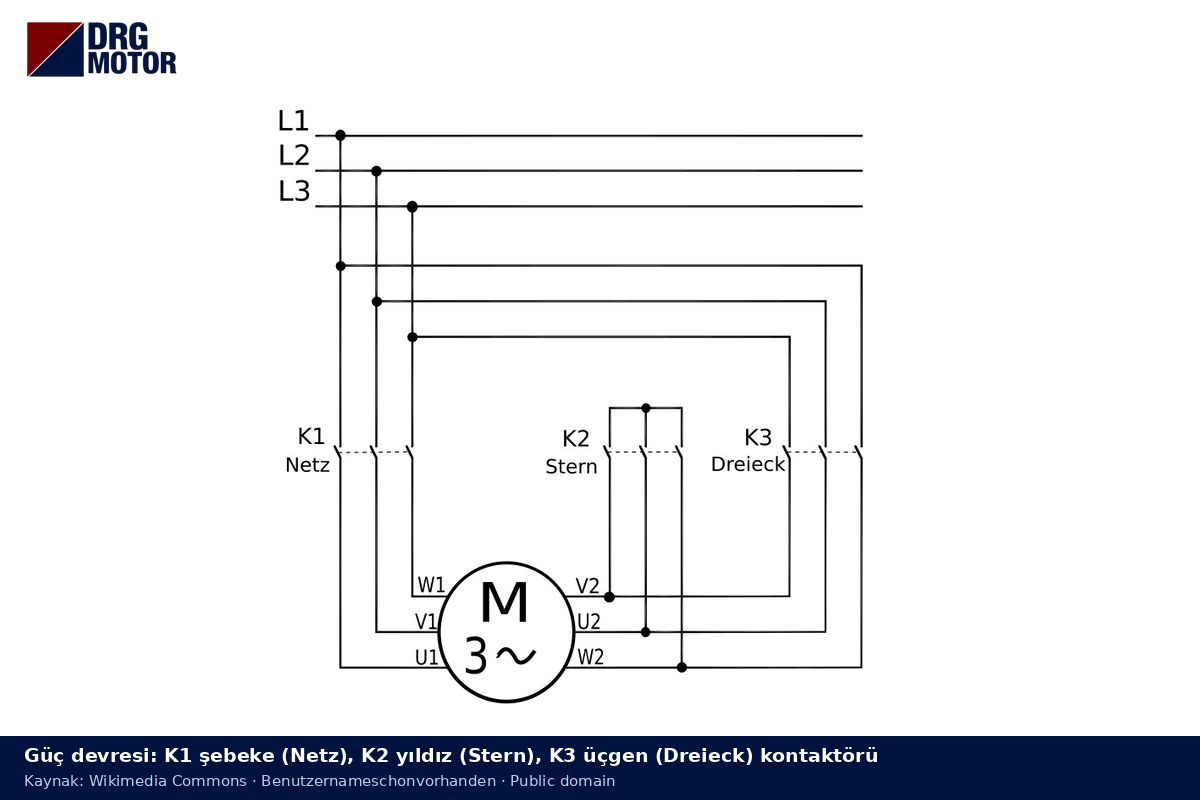
Star stage: K1 and K2 closed
When the start command is given, K1 and K2 close together and K3 stays open. The start ends of the windings are on the phases and the finish ends on the star point, so the motor starts at reduced winding voltage.
Delta stage: K1 and K3 closed
As the motor approaches rated speed, K2 drops out and, after a short pause, K3 closes. Each winding's finish end is now on the next phase; the windings see 400 V and the motor carries on with full torque. To follow the current path step by step, read star-delta power circuit diagram.
Control Circuit and Timing Chart
The control circuit decides the order in which the power contactors close. The diagram shows a stop button, a start button, K1's holding contact, a timer (KT) and electrical interlocking between K2 and K3.
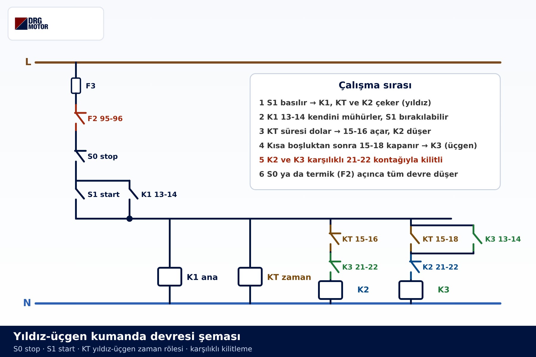
The logic runs like this: pressing start energises K2 and K1, and an auxiliary contact of K1 holds the circuit in so the motor keeps running after the button is released. The timer starts counting; when it expires it releases K2, and once K2's normally closed contact recloses, K3 picks up. K2's normally closed contact sits in the K3 branch and K3's in the K2 branch, so the two contactors can never be closed at the same time. If they were, the phases would be shorted through the winding ends.
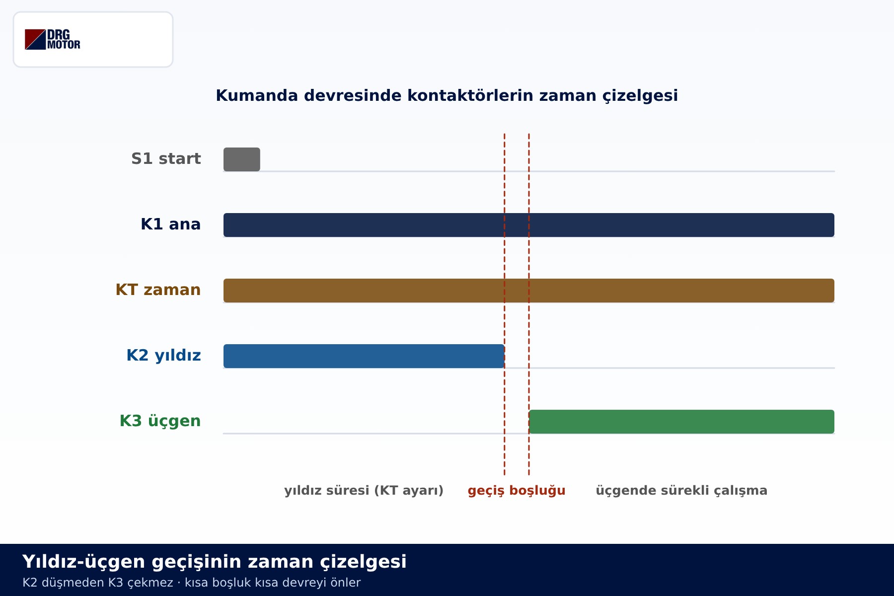
The timing chart shows the same sequence on a horizontal axis: K1 is closed throughout, K2 is closed in the first part, K3 in the last part, with a short gap between them. A line-by-line explanation of the control circuit and its typical fault symptoms is in star-delta control circuit diagram.
Contactor and Overload Currents, and the Starting Current Curve
How much current does each contactor carry?
A key feature of the star-delta circuit is that the contactors mostly carry the winding current, not the motor's line current. In delta operation K1 feeds the start side of the windings and K3 the finish side; both carry the winding current, about In/√3 (≈0.58 In). K2 only carries current during the star stage, and that current is about In/3.
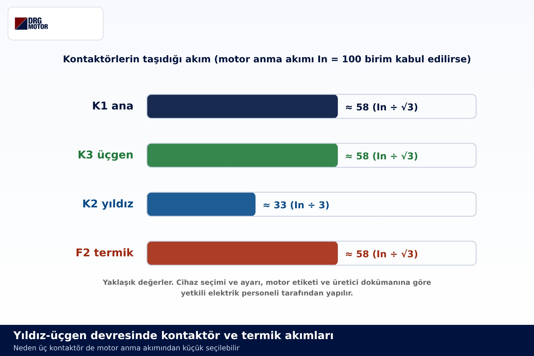
The overload relay F2 sits at the output of K1, in series with the windings, so it measures winding current rather than line current, and its setting logic follows from that. Device selection and settings depend on the motor nameplate, the manufacturer's documentation and the judgement of qualified electrical personnel; the diagrams explain the concept, and the installation belongs to a qualified electrician. A worked example for one power rating is given in 22 kW motor star-delta starting.
How does the starting current change?
On a direct-on-line start the motor draws several times its rated current at first, and this high current lasts until it reaches speed. With star-delta the first peak falls to about a third; at the changeover to delta a second, shorter current pulse appears. The size of that pulse depends on how far the motor has accelerated at the moment of changeover.
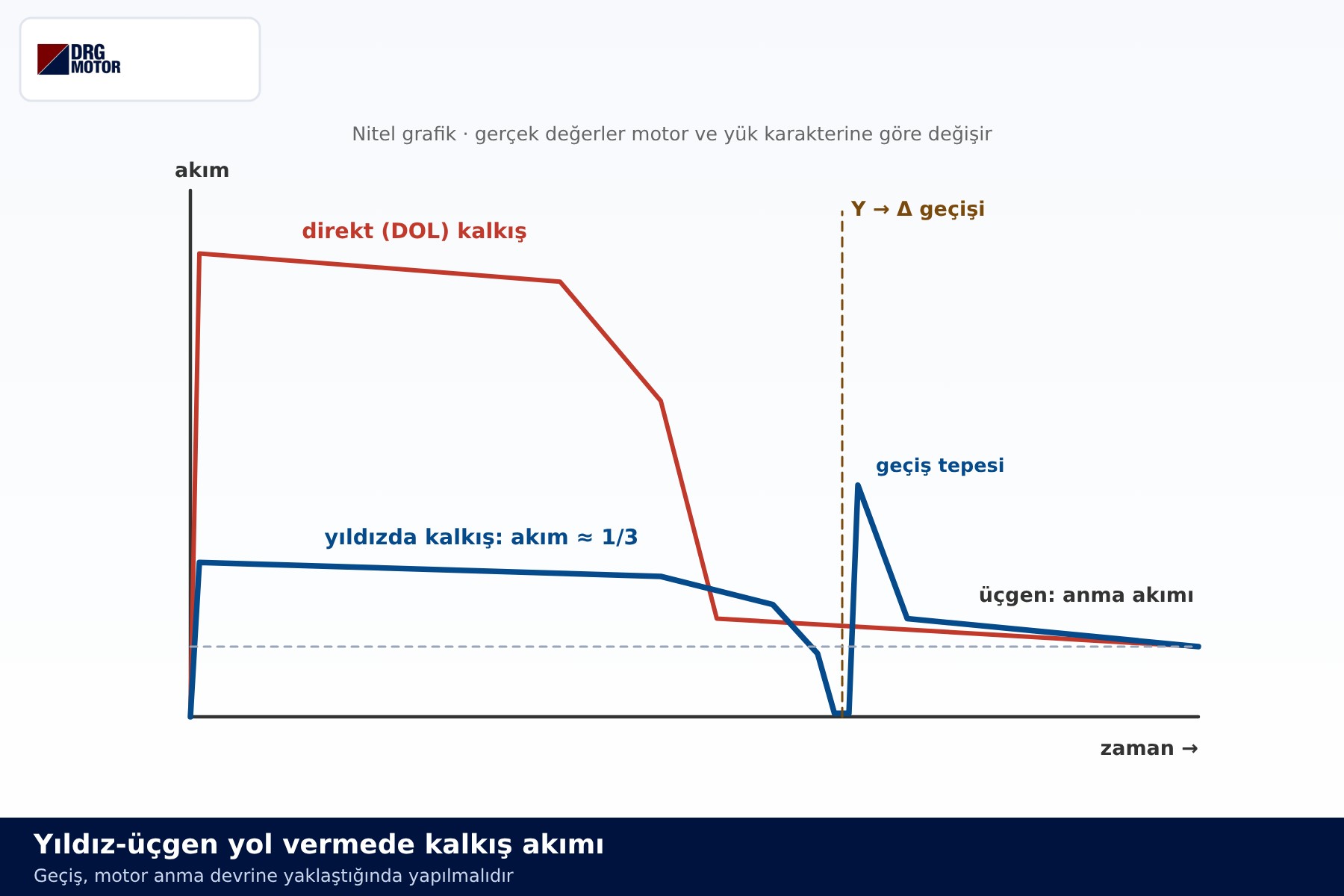
The curve in the source drawing below tells the same story: a lower, longer current zone in star, a brief interruption at changeover and then a short peak when delta is engaged.
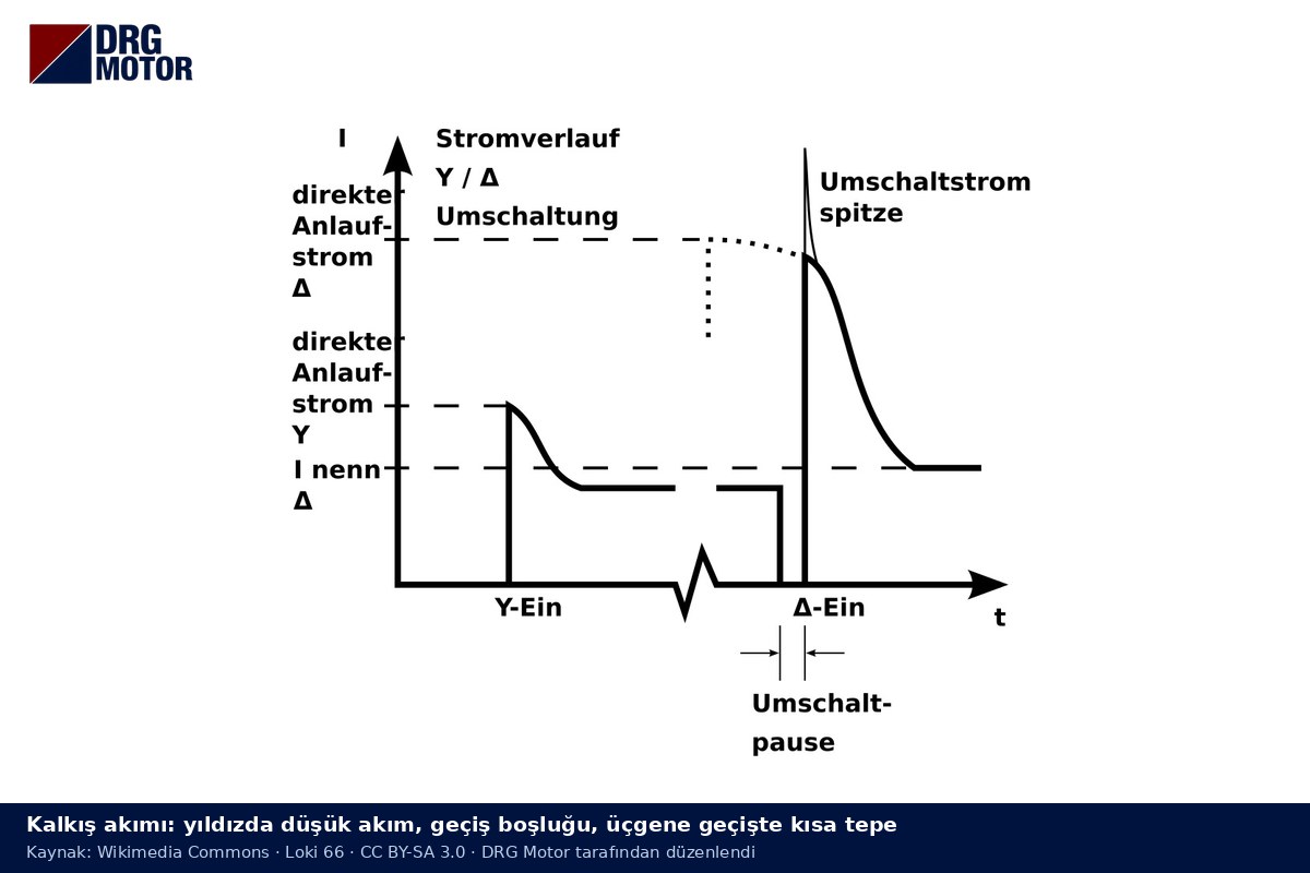
If the load cannot get close to rated speed on the reduced torque in star, the changeover pulse grows and the benefit of star-delta shrinks. In that case other starting methods are considered; for a comparison see star-delta vs soft starter.
DRG Motors Suitable for Star-Delta Starting
The models below are wound for 400/690 V Δ/Y: they run in delta on a 400 V supply and can be started in star, so they are suitable for star-delta starting. The whole family is on the three-phase asynchronous electric motors page, and a list you can filter by power and speed is on the buy electric motors online page.
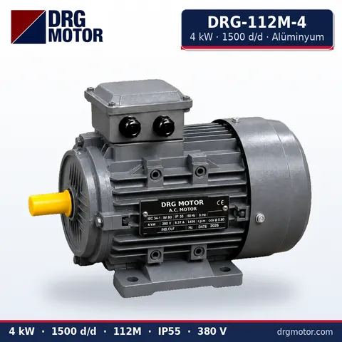
4 kW Three-Phase Motor 1500 rpm – DRG-112M-4 Aluminium
- 4 kW · 1500 rpm (4 poles)
- Aluminium frame · IEC 112M
- Mounting: B3 · B5 · B14 · B35
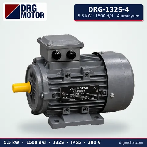
5.5 kW Three-Phase Motor 1500 rpm – DRG-132S-4 Aluminium
- 5.5 kW · 1500 rpm (4 poles)
- Aluminium frame · IEC 132S
- Mounting: B3 · B5 · B14 · B35
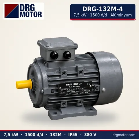
7.5 kW Three-Phase Motor 1500 rpm – DRG-132M-4 Aluminium
- 7.5 kW · 1500 rpm (4 poles)
- Aluminium frame · IEC 132M
- Mounting: B3 · B5 · B14 · B35
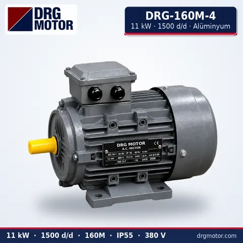
11 kW Three-Phase Motor 1500 rpm – DRG-160M-4 Aluminium
- 11 kW · 1500 rpm (4 poles)
- Aluminium frame · IEC 160M
- Mounting: B3 · B5 · B14 · B35
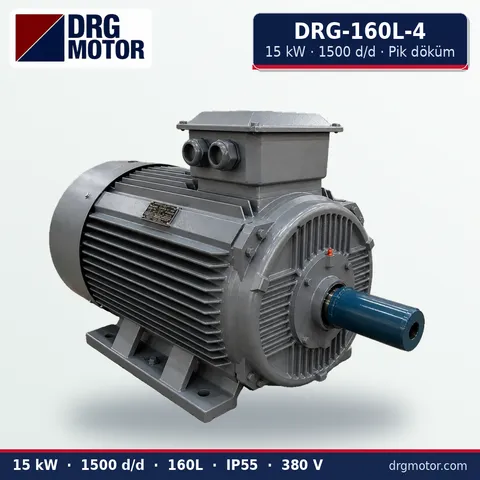
15 kW Three-Phase Motor 1500 rpm – DRG-160L-4 Cast Iron
- 15 kW · 1500 rpm (4 poles)
- Cast iron frame · IEC 160L
- Mounting: B3 · B5 · B14 · B35
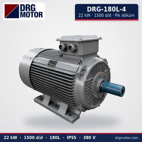
22 kW Three-Phase Motor 1500 rpm – DRG-180L-4 Cast Iron
- 22 kW · 1500 rpm (4 poles)
- Cast iron frame · IEC 180L
- Mounting: B3 · B5 · B14 · B35
Click to see current prices for these motors and order nowSEE PRICES →
Frequently Asked Questions
What is the difference between a star and a delta connection diagram?
In star the finish ends of the windings meet at one point and each winding sees the line voltage divided by √3. In delta the windings form a loop and each one sees the full line voltage. The same motor on the same supply produces about one third of the current and torque in star.
Can a motor rated 230/400 V be started star-delta?
Not on a 400 V supply. Such a motor is wound to run in star at 400 V; switched to delta, its windings would get 400 V and draw excessive current. In the DRG range this applies to motors up to 3 kW.
Why does a star-delta starter have three contactors?
K1 connects the motor to the supply, K2 forms the star point and K3 turns the windings into the delta loop. K2 and K3 are interlocked; closing both at once would mean a short circuit.
Why is the overload relay drawn after K1?
In that position the relay is in series with the windings and measures winding current, so the same relay protects the motor in both star and delta.
Are these diagrams available as one file?
Yes. All the diagrams in this article are in the star-delta connection diagrams PDF; how to read each page is explained in the star-delta wiring diagram PDF guide.





