English
 Türkçe
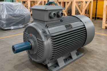
Connecting an electric motor to the supply correctly is the first condition for safe and efficient operation. In three-phase asynchronous motors, this connection is made in the terminal box on the housing. The star (Y) and delta (Δ) connection options we encounter here directly determine the voltage at which the motor will run, how much current it will draw, and how it will start. A wrong bridging can either prevent the motor from turning at all or cause it to burn out in a short time. At DRG Motor, in our IE3, IE4, and IE5 efficiency-class three-phase motors, a correct terminal connection is the foundation of both performance and safety. In this article we examine in detail the structure of the terminal box, the differences between star and delta connections, the meaning of the voltage values on the nameplate, and which connection to use on which supply.

What Is a Terminal Box?
The terminal box is the section where the ends of the motor's stator windings are brought out and the supply cables are connected. It is usually located on the motor housing inside a covered enclosure. Inside it there are six winding ends and the bridge plates used to connect them to one another. This seemingly simple box is where the critical connections that determine how the motor operates are made.
Winding Ends: U1-V1-W1 and U2-V2-W2
A three-phase motor has three windings. Since each winding has two ends, a total of six ends are brought out to the terminal box. These ends are standardly named U1, V1, W1 (start ends) and U2, V2, W2 (finish ends). This naming is an international standard, so no matter the brand of motor, the connection logic is the same.
The Function of the Bridge Plates
The bridge plates in the terminal box form a star or delta connection by joining the six winding ends in different ways. Changing the position of these plates allows the motor's connection type to be changed without physically removing any cable. Correct bridging is the key to operating the motor in line with the supply voltage.
How Is a Star (Y) Connection Made?
In a star connection the finish ends of the three windings (U2, V2, W2) are joined at one point; this point is called the star point or neutral point. The start ends (U1, V1, W1) are connected to the three phases of the supply. In the terminal box, this is achieved by bridging the U2-V2-W2 ends to one another with the bridge plates.
How Is a Delta (Δ) Connection Made?
In a delta connection the finish end of each winding is connected to the start end of the next winding; thus the windings are joined end to end to form a closed triangle. In the terminal box, this is done by bridging the U1-W2, V1-U2, and W1-V2 ends. The supply phases are again taken from the three corners.
The Concept of Line Voltage and Phase Voltage
To understand the connection types, two basic concepts must be separated. Line voltage is the voltage between two phases; phase voltage is the voltage between a phase and neutral. In a star connection the windings see the phase-to-neutral voltage, while in a delta connection they see the line voltage directly. This distinction is the source of the differences in current and torque.
Types of Current: Line Current and Winding Current
As with voltage, there are two concepts for current. Line current is the current drawn from the supply; winding current is the current passing through a single winding. In a star connection line current and winding current are equal; in a delta connection line current is about 1.73 times the winding current. This relationship is decisive in the selection of cables and protective devices.
The Basic Difference Between Star and Delta
The fundamental difference between the two connections is the voltage across each winding. In a star connection, each winding sees about 0.58 times (1/√3) the supply line voltage, while in a delta connection each winding sees the full line voltage. This difference directly affects the current the motor draws and the torque it produces.

Star and Delta Comparison Table
We have gathered the practical differences between the two connection types in the table below. This table lets you quickly see which connection is suitable in which situation.
| Property | Star (Y) | Delta (Δ) |
|---|---|---|
| Winding voltage | 0.58 times line voltage | Full line voltage |
| Current drawn from supply | Low | High |
| Starting torque | Low | High |
| Typical use | Starting / high supply voltage | Continuous running / low supply voltage |
| Power | About 1/3 of delta | Full power |
What Does 230/400V Δ/Y on the Nameplate Mean?
The expression "230/400V Δ/Y", which we often see on a motor nameplate, tells us that the motor can run on two different supplies. The first voltage here (230V) is for the delta connection, and the second (400V) is for the star connection. So on a supply with a 400V line voltage this motor is connected in star; on a supply with a 230V line voltage it is connected in delta. Reading these values correctly is very important, and we covered it in detail in our article on nameplate information.
Which Connection on Which Supply?
The golden rule for choosing the right connection is this: the voltage each winding sees must equal the winding voltage stated on the nameplate. The standard three-phase supply line voltage in many regions is 400V. A motor whose nameplate reads 400V Y / 230V Δ is connected in star on this supply. If connected in delta, each winding sees 400V; but it was designed for 230V, and in that case the motor draws excessive current and burns out.
The Consequences of a Wrong Connection
Connecting in delta a motor that should be connected in star applies voltage far above the design value to the windings. The result is rapid overheating and a burnt winding. Conversely, connecting in star a motor that should be connected in delta severely reduces the motor's power and torque; the motor cannot handle the load and is strained. Both errors lead to costly results.
Star-Delta Starting
One of the most common practical uses of the star and delta connections is star-delta starting. In this method the motor is connected in star at the moment of starting, so it draws a low current. After the motor reaches speed, it is switched to the delta connection and runs at full power. In this way the starting current is significantly reduced.
The Advantage of Star-Delta Starting
A directly started motor draws a current far above its rated current at start. The star-delta method reduces this starting current to about one third. This lessens the voltage drop on the supply and makes the selection of fuses and contactors easier. We covered why the starting current is so high in our article on starting current.
The Limit of Star-Delta Starting
This method has a cost: in the star position the motor's starting torque is also reduced. For this reason, star-delta starting is used only in applications that can start with no load or a light load. In machines that require a difficult start under load this method falls short, and soft starting or an inverter is preferred.
Connection with a Soft Starter and Inverter
When a soft starter or frequency inverter is used, the motor is usually connected with a single connection suited to the running supply (most often delta), and starting is controlled electronically. A frequency inverter both manages the starting current and provides energy saving through speed control.
Tightening Torque in Terminal Connections
Insufficient tightening of the terminal ends is one of the most common causes of failure in the field. A loose connection increases the contact resistance, which can lead to local heating, arcing, and ultimately a broken phase. Every connection should be tightened to the torque recommended by the supplier and checked periodically.

Overload and Connection Type
Because the connection type determines the current the motor draws, it also affects the overload protection setting. The thermal relay must be set according to the motor's connection type and nameplate current. A wrong setting causes the motor either to trip unnecessarily or to remain unprotected when it is truly strained. We covered this in our article on overload protection.
Environmental Conditions and the Terminal Box
High temperature and high altitude affect not only the motor but also the terminal connection. In hot environments cables and terminal ends heat up more, so the soundness of connections is even more important under these conditions. We examined the effect of environmental conditions on motor selection in our article on ambient temperature and altitude.
Phase Loss and the Terminal Connection
If an end loosens in the terminal box or a phase is interrupted, the motor may continue running on two phases. This situation is very dangerous; the motor draws abnormal current, overheats, and burns out in a short time. For this reason phase loss protection is as important as the correct terminal connection.
The Importance of the Three-Phase Supply
Star and delta connections give the expected result only on a balanced three-phase supply. Voltage imbalance between phases creates extra heating and vibration in the motor regardless of which connection is made. For this reason the health of the supply is as important as the connection. Our article on three-phase motor in industry, where we cover the topic in depth, is complementary in this respect.
Grounding in the Terminal Box
There is always a grounding connection point in the terminal box or on the motor housing. This point is critical for safety; when a leakage current occurs to the housing, the grounding safely conducts this current to earth and protects human life. Motor grounding must never be skipped.
Cable Cross-Section and Connection
A cable cross-section suitable for the current the motor draws must be selected. Since the current is lower in a star connection and higher in a delta connection, cable selection also varies with the connection type. A cable that is too thin heats up and causes energy loss; therefore the current calculation must be done carefully.
Connection in Dual-Speed Motors
Some motors can run at two different speeds by changing the pole count. These motors have more ends in the terminal box and more complex connection diagrams. We covered the relationship between pole count and speed in our article on pole count and speed.
Changing the Direction of Rotation
To change the direction of rotation of a three-phase motor, it is enough to swap the positions of any two phases in the terminal box. This simple operation reverses the direction of rotation of the motor's magnetic field. Making sure the direction of rotation is correct during commissioning is especially important for pumps and fans.
The Protection Class of the Terminal Box
The terminal box, like the rest of the motor, has a certain protection class. In dusty or humid environments the sealing of the box cover and the correct fitting of the cable glands are important. We covered this topic in detail in our article on IP protection class.
Checking the Connection Diagram
Most motors have a connection diagram on the inner face of the terminal box cover or on the nameplate. Before commissioning, this diagram must be read and the bridging done accordingly. Whenever in doubt, the voltage values on the motor nameplate and the supply voltage should be compared.
Terminal Box Maintenance
The terminal box is an overlooked but important part of periodic maintenance. Moisture condensation inside the box, dust accumulation, or loosening ends cause problems over time. During maintenance the cover gasket, cable glands, and terminal ends should be checked; if there is any sign of oxidation, it should be cleaned. A sound terminal box is the guarantee of a safe connection.
Cold Connections and Contact Resistance
A loose or oxidized connection creates a high-resistance contact known as a "cold connection". This point heats up under load, deteriorates further over time, and eventually arcs to create a fault. The temperature rise also upsets the motor's overall heat balance; this is why connection quality should be considered together with temperature control.
The Relationship Between Connection and Efficiency
A correct connection allows the motor to reach its rated efficiency. Wrong bridging or loose ends cause both power loss and extra heating, reducing efficiency. The first condition for obtaining the expected saving from high-efficiency IE3, IE4, and IE5 motors is a flawless terminal connection.
Verifying the Connection Type During Commissioning
During commissioning, before energizing the motor, the position of the bridge plates should be checked visually, and then at first run the current drawn by the motor should be measured with a clamp meter. If the measured current is close to the nameplate current, the connection is correct. A current much higher than expected is the first and clearest sign of wrong bridging; in that case the motor should be stopped immediately.
The Relationship Between Insulation Class and Connection Safety
A correct connection allows the motor to run at its designed voltage and thus lets the insulation complete its intended life. A wrong connection raises the winding temperature and ages the insulation quickly. Insulation class and connection safety are therefore intertwined.
Ways to Prevent Connection Errors
The safest way to prevent connection errors is to read the nameplate carefully, measure the supply voltage, follow the connection diagram, and tighten the ends to the correct torque. Checking once more before commissioning prevents costly failures later. A hurried connection puts even the highest-quality motor at risk.
DRG Motor Support for the Right Connection
Although the terminal box may look like a small section, we have seen that the safe operation of a three-phase motor is determined precisely here. Knowing the difference between star and delta connections, reading the voltage values on the nameplate correctly, and making the bridging suitable for the supply directly affect the motor's life and performance. At DRG Motor, we offer our IE3, IE4, and IE5 efficiency-class three-phase asynchronous motors with connection options suited to your supply conditions. For the right connection, the right starting method, and the right protection, you can review our industrial electric motors page. If you are curious about the working principle of electric motors, our what is an electric motor article will be a good starting point.