 English
 Le français
 Türkçe





The star-delta wiring diagram PDF is a free 12-page set prepared by DRG Motor that puts the motor windings, terminal links, power and control circuits, contactor currents and the starting current curve in one file. This guide explains what each page shows, the order in which to read the diagrams and what to check when you compare them with a real panel.
📄 Download the star-delta wiring diagram PDF (12 pages, landscape A4, free; ready to print and pin inside a panel).
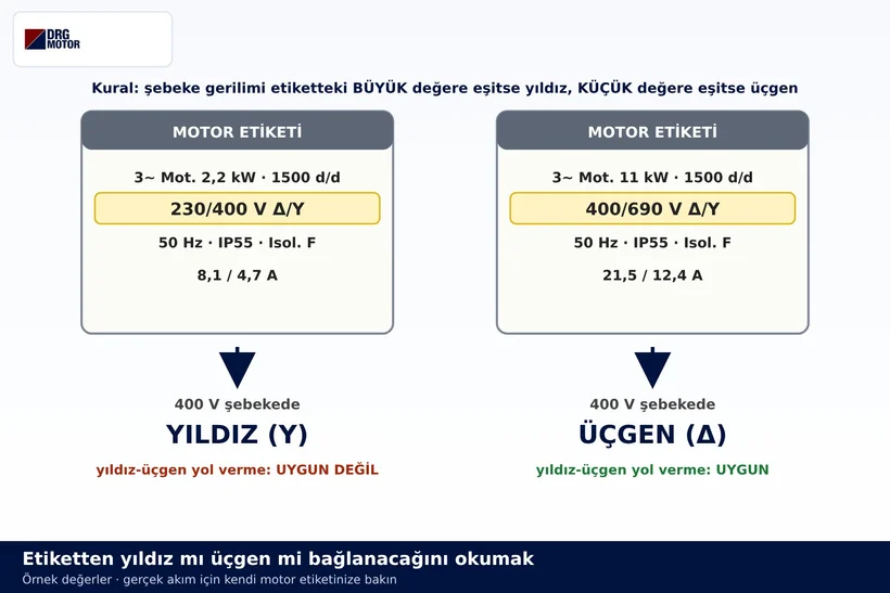
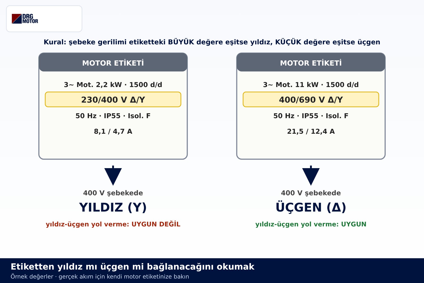
The cover image is page 5 of the PDF: reading the nameplate to decide whether the motor runs in star or delta on a 400 V supply. Everything else in the set builds on that decision, because a star-delta starter only makes sense for a motor that runs in delta on 400 V.
What Is in the PDF? The 12 Pages at a Glance
The pages move from concept to application. Pages 1–4 cover the motor itself (windings, terminal box, voltage and current), page 5 covers the nameplate, pages 6–10 cover the starter panel and the last two pages show how large the currents are.
| Page | What it shows | What to look for |
|---|---|---|
| 1 | Winding arrangement in star and delta | Star has one common point, delta forms a closed ring |
| 2 | Star terminal link | W2-U2-V2 on the lower row joined by one link |
| 3 | Delta terminal links | Three vertical links: U1–W2, V1–U2, W1–V2 |
| 4 | Voltage and current comparison table | Winding voltage is U/√3 in star and U in delta |
| 5 | Reading the nameplate | Supply equal to the higher value means star, equal to the lower value means delta |
| 6 | Power circuit diagram | Position of Q1, K1, K2, K3 and F2 |
| 7 | Power circuit – star stage | K1 and K2 closed, K3 open |
| 8 | Power circuit – delta stage | K1 and K3 closed, K2 open |
| 9 | Control circuit diagram | Holding contact, timer, interlocking |
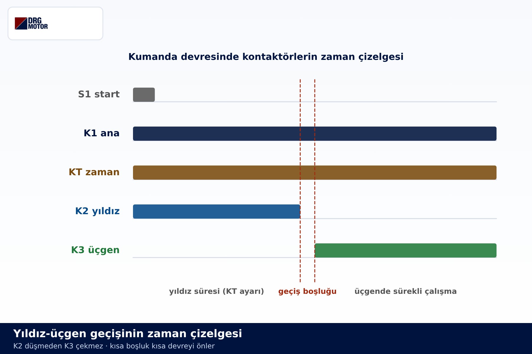
| 10 | Timing chart | K3 closes only after K2 drops out, with a short gap |
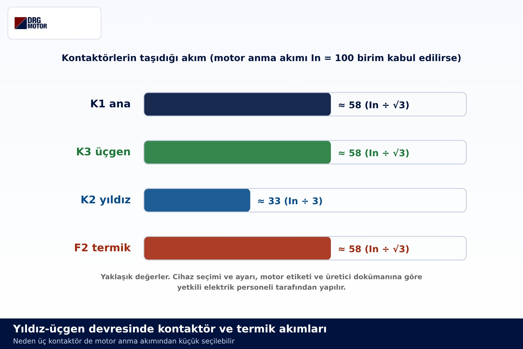
| 11 | Contactor and overload relay currents | K1, K3 and F2 ≈ 0.58 In; K2 ≈ In/3 |
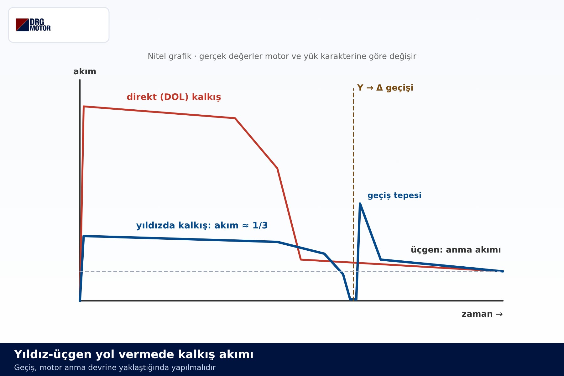
| 12 | Starting current curve | Qualitative comparison of direct-on-line and star-delta starting |
The diagrams explain the concept. How a panel is built, which devices are chosen and how they are set depends on the motor nameplate, the device manufacturer’s documentation and the judgement of a qualified electrician.
Pages 1–4: Reading the Inside of the Motor
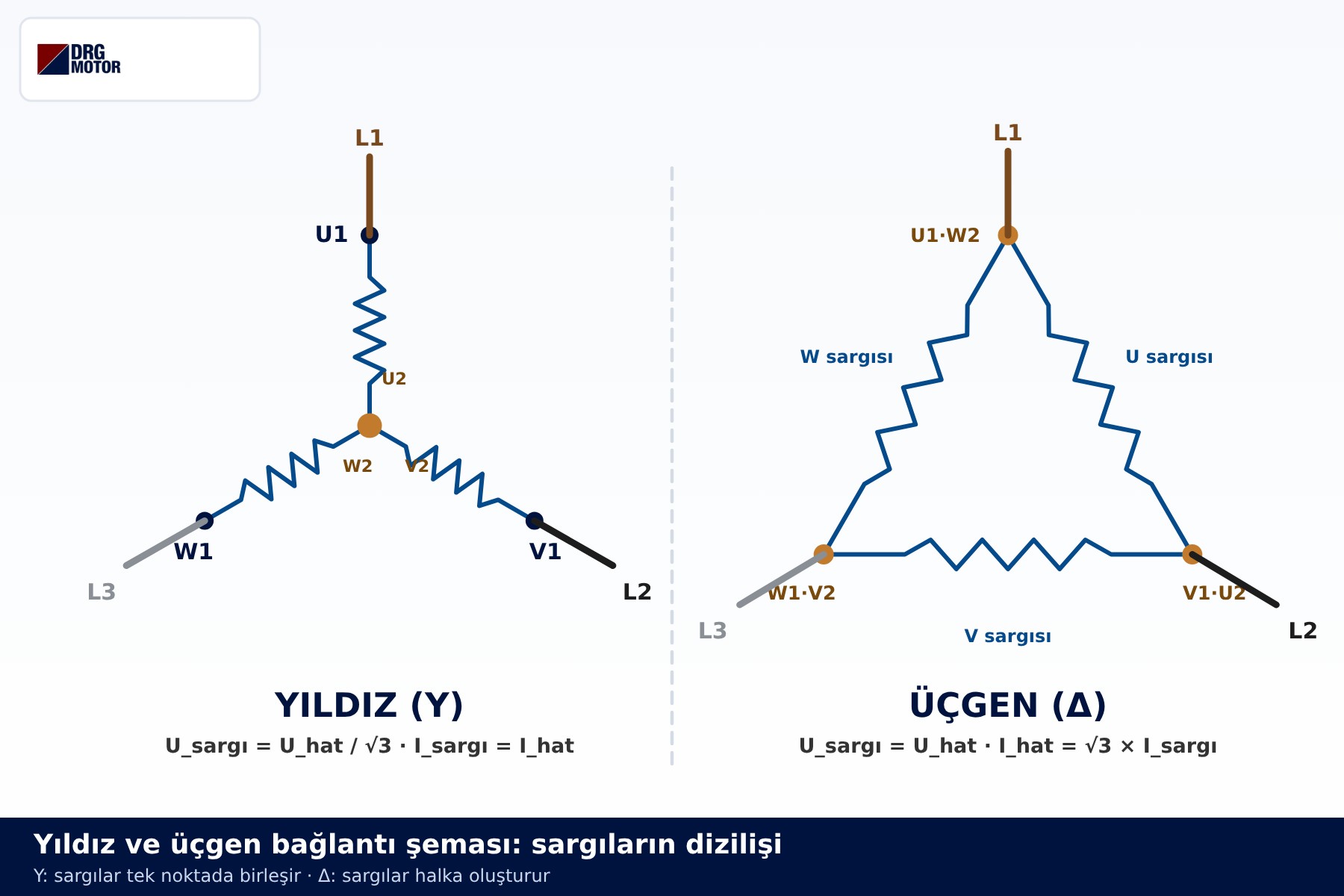
Page 1 is the foundation. A three-phase induction motor has three separate windings, U, V and W, each with a start (U1, V1, W1) and an end (U2, V2, W2). In star, the three ends meet at one point and L1-L2-L3 go to the starts. In delta, the end of each winding is joined to the start of the next, forming a closed ring. For the theory behind this, read what is a star-delta connection; for a line-by-line walk through the diagram, see the electric motor star-delta connection diagram guide.
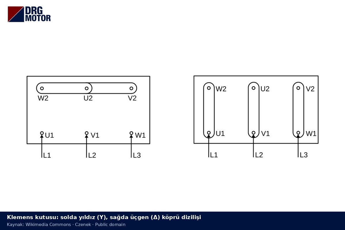
Pages 2 and 3 show the same idea inside the terminal box. The upper row reads U1 V1 W1 and the lower row W2 U2 V2; this offset order lets the delta links be straight vertical bars. In star, the lower row is shorted by one link; in delta, three vertical links are fitted. Terminal links are covered in detail in motor terminal star-delta connection and 3-phase motor wiring diagram: terminal links, so these two pages are included as a quick reference only.
The table on page 4 sums up why the method works. On a 400 V supply, a star-connected winding sees 400/√3 ≈ 231 V, while a delta-connected winding sees the full 400 V. Since √3 ≈ 1.732, the same motor on the same supply draws about 1/3 of the starting current and produces about 1/3 of the torque in star. In delta, line current is √3 times the winding current.
It also helps to read the PDF terminal pages alongside this simple terminal-board drawing: star on the left, delta on the right.
Page 5: The Nameplate Decision Comes First
When you open the PDF, go to page 5 first and then look at the motor’s nameplate. Two voltages are printed on it. If the supply voltage equals the higher value, the motor is connected in star; if it equals the lower value, it is connected in delta. The two examples on the page show this:
- A motor marked 230/400 V Δ/Y runs in star on a 400 V supply. Its normal running connection is already star, so it is not suitable for star-delta starting; switched to delta, each winding would see 400 V and be damaged.
- A motor marked 400/690 V Δ/Y runs in delta on a 400 V supply. It can be held in star briefly during start-up and then switched to delta, so it is suitable for star-delta starting.
In the DRG range, motors up to 3 kW are wound for 230/400 V and motors from 4 kW upwards for 400/690 V. In practice, the panel diagrams in the PDF therefore apply to motors of 4 kW and above. The power limit is discussed in which kW motor uses star or delta, and star-delta is compared with other methods in star-delta vs soft starter.
Click to see current electric motor prices and order nowSEE PRICES →
Pages 6–8: Reading the Power Circuit in Three Steps
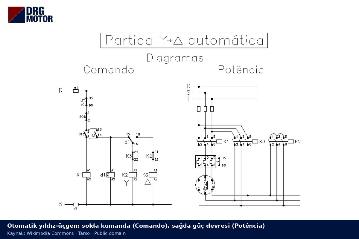
Page 6 shows the starter’s power circuit in a single drawing. Follow the current from top to bottom: L1-L2-L3 pass through the Q1 protective device and then the K1 main contactor. The output of K1 splits in two: one path runs through the F2 overload relay to the motor terminals U1-V1-W1, the other goes to the K3 delta contactor. The motor terminals W2-U2-V2 are wired both to K3 and to the K2 star contactor; when K2 closes, these three ends are joined at the star point.
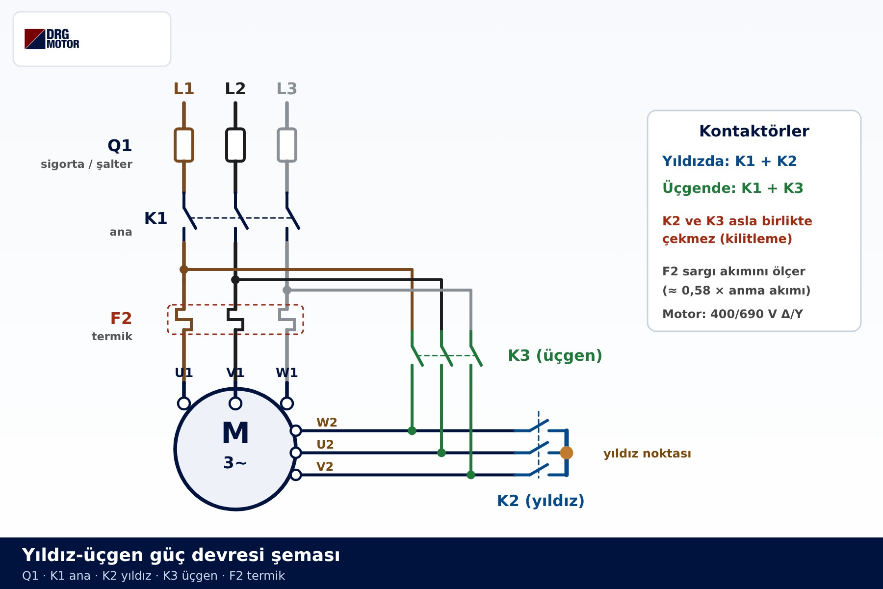
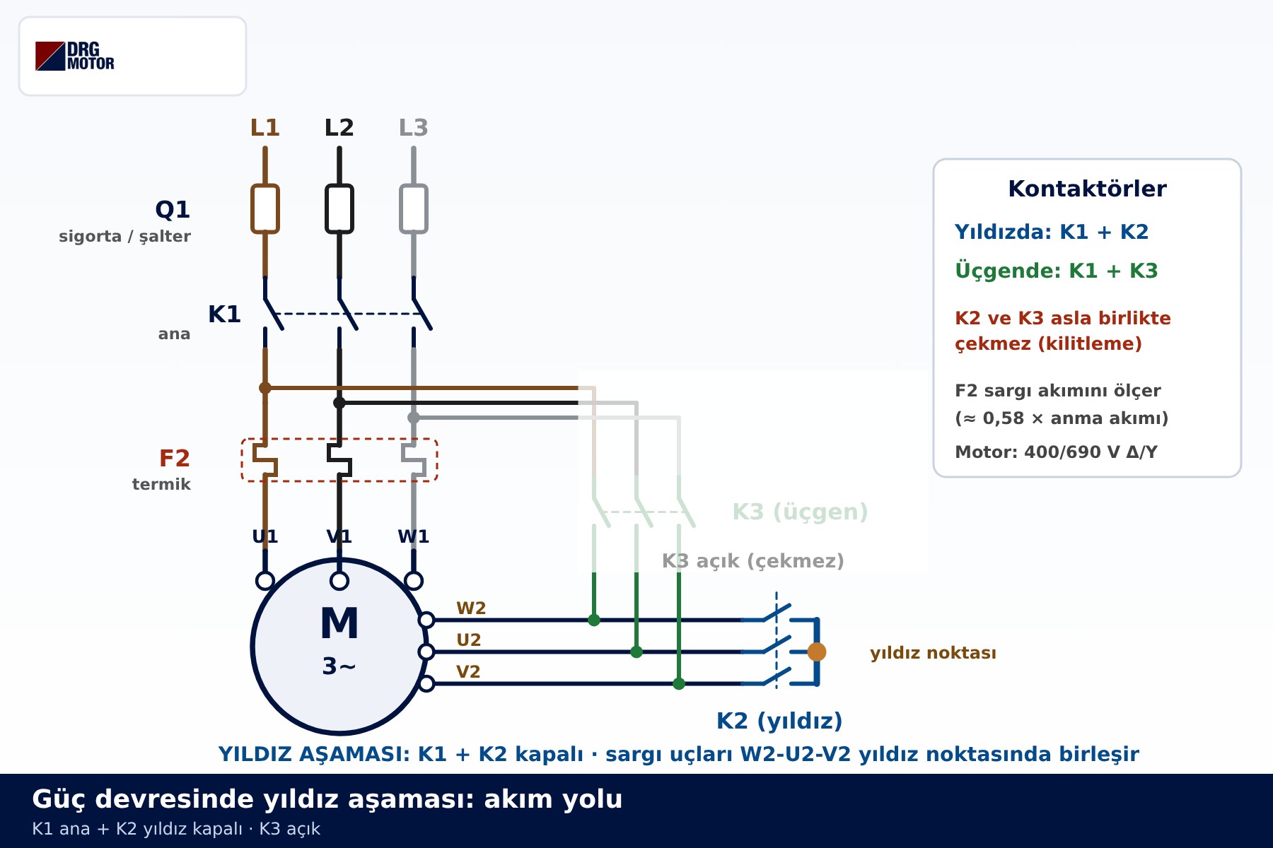
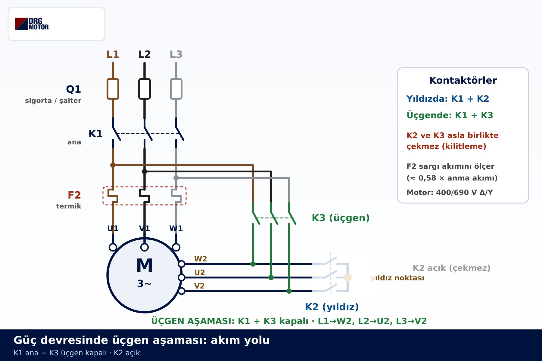
Pages 7 and 8 show the same diagram at two moments. In the star stage, K1 and K2 are closed and K3 is open: the winding ends are shorted at the star point. In the delta stage, K2 opens and K3 closes: W2-U2-V2 are connected to L1, L2 and L3 respectively, giving L1→U1·W2, L2→V1·U2, L3→W1·V2, so the contactor builds the same ring that the delta links make in the terminal box. The current path for both stages is drawn step by step in star-delta power circuit diagram.
Pages 9–10: Control Circuit and Timing Chart
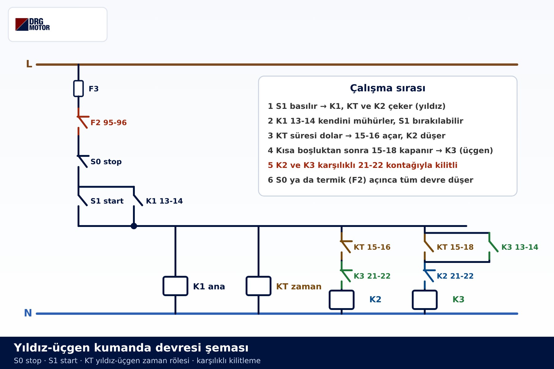
Page 9 is the control circuit. Read it from left to right: the F3 control fuse, the 95-96 contact of the F2 overload relay and the stop button are in series, so opening any of them drops the whole circuit. Pressing the start button energises K1, the KT timer and K2; the 13-14 auxiliary contact of K1 bridges the start button and holds the circuit in. When the KT time runs out, contact 15-16 opens and K2 drops out, then contact 15-18 closes and K3 picks up. The 21-22 contacts in the K2 and K3 branches provide interlocking: while one is energised, the other cannot close.
The timing chart on page 10 shows the same events along a horizontal axis. K1 and KT pick up with the start command and stay in until the motor is stopped. The K2 bar ends, there is a short gap, and then the K3 bar begins. That gap prevents the delta contactor from closing before the star point has opened, which would short two phases. How long the motor stays in star depends on the load; the PDF deliberately gives no number. The full logic and common control faults are explained in star-delta control circuit diagram.
Another drawing showing control and power on one page (Comando = control, Potência = power).
Pages 11–12: Why the Contactors Can Be Smaller
Page 11 takes the motor rated current (In) as 100 units and shows the approximate current through each device as a bar. K1 and K3 carry the winding current: ≈ In/√3, or about 0.58 In. K2 carries current only in the star stage, and that current is ≈ In/3. The overload relay sits after K1 in the winding branch, so it also measures the winding current, ≈ 0.58 In. This is why the contactors in a star-delta panel can be rated below the motor current; the actual selection and setting remain a matter for the nameplate, the manufacturer’s documentation and a qualified electrician. For a worked power example, see 22 kW motor star-delta starting.
Page 12 is a qualitative chart. The red curve shows the high initial current of a direct-on-line start; the blue curve shows that peak cut to roughly one third in star. A short current peak appears at the star-to-delta changeover. If the changeover happens close to rated speed, the peak stays small; switch too early and the peak grows, eroding the benefit of star-delta.
Using the PDF on Site: A Checklist
The PDF is not an installation manual. Use it as a checklist when you compare an existing panel, or a motor you are about to buy, with the diagrams:
- Does the nameplate read 400/690 V Δ/Y? (page 5) If not, a star-delta panel is not suitable for this motor.
- Are six leads running from the panel to the motor? With star-delta, no links are fitted in the terminal box; K2 and K3 do that job (page 6).
- Are the terminal markings in the same order as the diagram: U1 V1 W1 on top, W2 U2 V2 below? (pages 2–3)
- Does the control diagram include interlocking between K2 and K3? (page 9)
- Is the overload relay in the winding branch after K1? (pages 6 and 11)
- Does the motor start in star and reach close to rated speed before switching to delta? (pages 10 and 12)
- If the motor turns the wrong way, leave the correction to a qualified electrician; the phase sequence must stay the same in both stages.
The diagram set itself is always available at star-delta wiring diagram PDF.
Who Is the PDF For?
The set was drawn with three readers in mind: a vocational student working through star-delta starting, a maintenance technician trying to interpret a panel, and a plant owner checking a nameplate before replacing a motor. Each page carries one idea and can be printed on its own; the title strip at the bottom states what the drawing is meant to show. Drawings and table values assume an ideal, balanced supply; on a real motor, currents are read from the nameplate.
DRG Motor is an electric motor manufacturer, supplier and seller. Contactors, overload relays and timers are not part of the DRG range; please source them from your panel component supplier. On the motor side, the 4 kW and larger models in the three-phase asynchronous electric motors family are wound for 400/690 V and are suitable for star-delta starting on a 400 V supply. All models are listed by power, speed and frame on the buy electric motors online page.
DRG Motors Suitable for Star-Delta Starting
The 4-pole models below are marked 400/690 V Δ/Y on the nameplate. They run in delta on a 400 V supply and can be started in star-delta with the power and control diagrams in the PDF. IP55 protection, class F insulation, IC411 cooling.
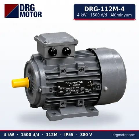
4 kW Three-Phase Motor 1500 rpm – DRG-112M-4 Aluminium
- 4 kW · 1500 rpm (4 poles)
- Aluminium frame · IEC 112M
- Mounting: B3 · B5 · B14 · B35
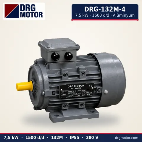
7.5 kW Three-Phase Motor 1500 rpm – DRG-132M-4 Aluminium
- 7.5 kW · 1500 rpm (4 poles)
- Aluminium frame · IEC 132M
- Mounting: B3 · B5 · B14 · B35
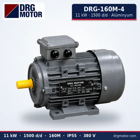
11 kW Three-Phase Motor 1500 rpm – DRG-160M-4 Aluminium
- 11 kW · 1500 rpm (4 poles)
- Aluminium frame · IEC 160M
- Mounting: B3 · B5 · B14 · B35
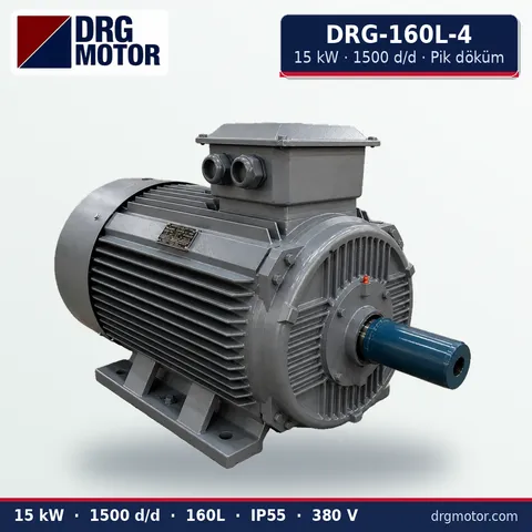
15 kW Three-Phase Motor 1500 rpm – DRG-160L-4 Cast Iron
- 15 kW · 1500 rpm (4 poles)
- Cast iron frame · IEC 160L
- Mounting: B3 · B5 · B14 · B35
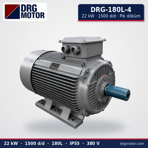
22 kW Three-Phase Motor 1500 rpm – DRG-180L-4 Cast Iron
- 22 kW · 1500 rpm (4 poles)
- Cast iron frame · IEC 180L
- Mounting: B3 · B5 · B14 · B35
Click to see current prices for these motors and order nowSEE PRICES →
Frequently Asked Questions
Is the star-delta wiring diagram PDF free?
Yes. You can download the 12-page PDF here without registering and print it for training or in-house use.
Does the panel diagram in the PDF apply to every motor?
No. It applies only to motors that run in delta on a 400 V supply, that is, motors marked 400/690 V Δ/Y. A 230/400 V motor runs in star on 400 V and is not suitable for star-delta starting.
Why does the PDF give no timer or overload relay settings?
These values depend on the motor’s rated current, the starting behaviour of the load and the device manufacturer’s documentation. A single generic number would be misleading; setting them is a job for a qualified electrician.
Are terminal links fitted in a star-delta connection?
No. Six leads run from the motor to the panel, and the K2 and K3 contactors take over the role of the star and delta links. Terminal links are used only when a motor runs in star or permanently in delta.





