English
 Le français
 Türkçe




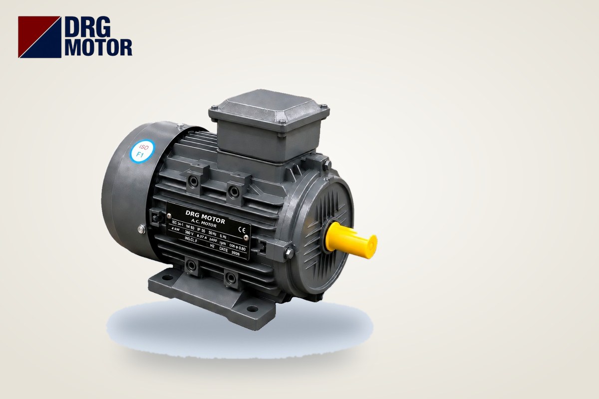

A 3-phase motor wiring diagram is built on the six terminals in the terminal box: U1 V1 W1 sit on the top row, W2 U2 V2 on the bottom row, and the supply phases L1 L2 L3 always go to the top row. In a star connection, W2, U2 and V2 on the bottom row are shorted together with horizontal links; in a delta connection, three vertical links join U1–W2, V1–U2 and W1–V2. The nameplate decides which to use: on a 380–400 V supply, a motor marked 230/400 V is connected in star and a motor marked 400/690 V in delta. In our store, models up to 3 kW are marked 230/400 V (star) and those from 4 kW upwards 400/690 V (delta).
Working in a terminal box is life-threatening when live: the connection must be made by a qualified electrician, the supply must be isolated and locked off before starting, and the absence of voltage must be confirmed with a tester. The steps below describe the on-site work sequence for an electrician wiring a motor for the first time or commissioning a replacement. If you have not yet chosen the motor, the nameplate values of every power and speed are on the Buy Electric Motors Online page.
In What Order Are the 6 Terminals Arranged in the Terminal Box?
Each phase winding has a start (1) and an end (2): winding U is U1–U2, winding V is V1–V2, winding W is W1–W2. On the terminal board these ends are not placed at random but staggered so that the links fit easily. When you open the cover, this is the layout you will see:
| Row | Left | Centre | Right |
|---|---|---|---|
| Top row (supply input) | U1 ← L1 | V1 ← L2 | W1 ← L3 |
| Bottom row (winding ends) | W2 | U2 | V2 |
The bottom row being shifted to W2-U2-V2 is no accident. Because W2 sits directly below U1, a vertical link connects the start of winding U to the end of winding W; three vertical links thus form a closed delta. Joining the three bottom terminals horizontally, on the other hand, gathers the ends of the three windings at a common point, creating the star point. The same link plates are used in both connections; only their orientation changes. For mechanical details such as the box body, gasket and cable entry, see the article on the motor terminal box and cable entry.
Step 1: Star or Delta According to the Nameplate Voltage?
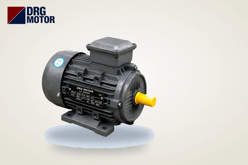
The nameplate shows two voltages and two symbols, e.g. "230/400 V Δ/Y" or "400/690 V Δ/Y". The rule is simple: whichever nameplate value equals the line-to-line supply voltage, connect with the symbol under that value. Since the industrial supply in Türkiye is 380–400 V:
- Motor marked 230/400 V Δ/Y: 400 V corresponds to star → connect in star at 380 V.
- Motor marked 400/690 V Δ/Y: 400 V corresponds to delta → connect in delta at 380 V; it is also suitable for star-delta starting.
Example models from our catalogue data and the nameplate currents to read at 380 V:
| Model | Power / speed | Nameplate voltage | Connection at 380 V | In 380 V | In 400 V | Cable entry |
|---|---|---|---|---|---|---|
| DRG-90L-4 | 1.5 kW / 1445 rpm | 230/400 V | Star (Y) | 3.47 A | 3.3 A | 1 × M25×1.5 |
| DRG-100L2-4 | 3 kW / 1450 rpm | 230/400 V | Star (Y) | 6.34 A | 6.02 A | 1 × M25×1.5 |
| DRG-112M-4 | 4 kW / 1450 rpm | 400/690 V | Delta (Δ) | 8.37 A | 7.95 A | 2 × M32×1.5 |
| DRG-132S-4 | 5.5 kW / 1460 rpm | 400/690 V | Delta (Δ) | 11.2 A | 10.7 A | 2 × M32×1.5 |
| DRG-160M-4 | 11 kW / 1465 rpm | 400/690 V | Delta (Δ) | 21.5 A | 20.4 A | 2 × M40×1.5 |
| DRG-180L-4 | 22 kW / 1470 rpm | 400/690 V | Delta (Δ) | 41.8 A | 39.7 A | 2 × M40×1.5 |
Of the 120 models in the store, 43 are marked 230/400 V (0.25–3 kW) and 77 are marked 400/690 V (4 kW and above). Still, determine the connection from the nameplate every time rather than from memory: an older motor or one from another source may have a different winding voltage at the same power.
Step 2: How Are the Star or Delta Links Fitted?
Before fitting the links, loosen the nuts, clean the plates and take a photo of the old connection. The links are the brass or copper plates supplied with the terminal box; do not replace them with a piece of wire or a thin strip.
Star (Y) link layout
| Row | Left | Centre | Right |
|---|---|---|---|
| Top | U1 ← L1 | V1 ← L2 | W1 ← L3 |
| Link | horizontal: W2 ═ U2 ═ V2 (two plates, along the bottom row) | ||
| Bottom | W2 | U2 | V2 |
In star there is no link between the top terminals. Each winding sees the line voltage divided by √3: on a 380 V supply, 380 / √3 ≈ 219 V. That is the design voltage of a 230/400 V winding.
Delta (Δ) link layout
| Row | Left | Centre | Right |
|---|---|---|---|
| Top | U1 ← L1 | V1 ← L2 | W1 ← L3 |
| Link | vertical ║ | vertical ║ | vertical ║ |
| Bottom | W2 | U2 | V2 |
In delta each winding sees the full line voltage, i.e. 380 V; a 400/690 V winding is designed for this. The three plates are fitted vertically, each connecting a supply terminal on the top row to the winding end below it.
Step 3: Connecting the L1 L2 L3 and PE Cables to the Terminals
With the links in place, the supply cable is brought into the box. Work sequence:
- Pass the cable through a gland that matches the motor's cable entry. According to catalogue data, 90L–100L frames have 1 × M25×1.5, 112M–132 frames 2 × M32×1.5 and 160–180 frames 2 × M40×1.5 entries. Close any unused entry with a blanking plug.
- Fit ring lugs that match the conductor size and the terminal stud diameter, and crimp them with the proper crimping tool. Wrapping a stranded conductor round the stud without a lug causes loose contact and heating.
- Connect L1 to U1, L2 to V1 and L3 to W1. The lug sits on top of the link plate; no washer or nut should be between them.
- Tighten the nuts to the torque specified by the motor manufacturer, with a torque wrench if available. Over-tightening can crack the stud or the insulator; leaving them loose leaves arc marks and burnt terminals.
- Connect the green-yellow PE conductor to the earthing screw in the terminal box; if the frame has a separate earthing point, use it as well according to the installation design.
- The cable sheath should end inside the gland and the cores must not rub against sharp edges; refit the gasket and cover screws.
To size the cable for current and distance, use the motor cable size calculator.
Step 4: How Is the Direction of Rotation Checked at First Start?
In the commonly accepted convention, with L1-U1, L2-V1, L3-W1 and a correct supply phase sequence, the motor turns clockwise viewed from the shaft end. Yet the phase sequence on site is not always known, so:
- If possible, run the motor briefly uncoupled from the load, or check the direction before fitting the coupling.
- If it runs the wrong way, swap any two phases (e.g. L1 and L2). Do not touch the links; link orientation does not change the rotation.
- Preferably make the change on the panel side, at the motor output terminals, so the layout in the motor box stays standard.
In pump, fan and gearbox systems, reverse rotation can cause damage quickly. For the causes in detail, see our article on why an electric motor runs backwards.
Why Are the Links Removed for Star-Delta Starting?
In star-delta starting, the linking is done not by the plates in the motor box but by the contactors in the panel. So all links are removed from the terminal board and each of the six terminals receives its own conductor:
| Terminal | Connected to | Function |
|---|---|---|
| U1, V1, W1 | Line (main) contactor output L1, L2, L3 | Feeds the winding starts continuously |
| W2, U2, V2 | L1, L2, L3 via the delta contactor | Does the job of the vertical links (U1–W2, V1–U2, W1–V2) |
| W2, U2, V2 | Star contactor (output shorted internally) | Does the job of the horizontal link, forming the star point at start |
This method applies only to motors that run in delta at 380–400 V, i.e. those marked 400/690 V; a motor marked 230/400 V cannot be started star-delta, because the moment it switches to delta its winding sees 380 / 230 ≈ 1.65 times its design voltage. The current in each cable set is the winding current: 21.5 / √3 ≈ 12.41 A for the 11 kW DRG-160M-4 and 41.8 / √3 ≈ 24.13 A for the 22 kW DRG-180L-4. For contactor and overload currents, use the star-delta starting tool. The theory of the link geometry and the concepts of line and phase voltage are explained in our article on star and delta terminal connection.
How Do You Spot a Wrong Connection? Commissioning Checklist
The two most frequent mistakes are fitting links without reading the nameplate, and both are quickly revealed with a clamp meter:
- A 230/400 V motor connected in delta at 380 V: the winding sees 380 V instead of 219 V. The motor draws high current even at no load, hums louder and heats up quickly. For example, on the 3 kW DRG-100L2-4 with a nameplate current of 6.34 A, if you read a no-load current approaching or exceeding this value, stop immediately.
- A 400/690 V motor left in star at 380 V: each winding gets about 219 V and torque falls to one third. The motor looks normal at no load, but under load its speed drops, its current rises above the nameplate value (8.37 A for the 4 kW DRG-112M-4) and the overload trips.
Complete this list before handing over the motor:
- I determined the connection type from the nameplate voltage and symbol (230/400 V → Y, 400/690 V → Δ).
- I checked the number and orientation of the link plates; for star-delta I removed all links.
- I confirmed that the lugs suit the conductor size and stud, and that the nuts are tightened to the correct torque.
- I connected the PE conductor to the earthing screw and had an electrician carry out a continuity test.
- I closed the cable entries with glands and plugs, and refitted the gasket and cover.
- I saw the direction of rotation at first start; if reversed, I swapped two phases.
- I measured the three phase currents with a clamp meter; the values are close to each other and below the nameplate current under load.
- I set the overload relay to the correct current: In for direct-on-line, In/√3 for star-delta.
For the logic of overload and fuse selection, see the overload relay, fuse and contactor selection tool.
Motors Used in the Connection Examples
- DRG-90L-4 – 1.5 kW – 1500 rpm – 90L aluminium (230/400 V, star)
- DRG-100L2-4 – 3 kW – 1500 rpm – 100L aluminium (230/400 V, star)
- DRG-112M-4 – 4 kW – 1500 rpm – 112M aluminium (400/690 V, delta)
- DRG-132S-4 – 5.5 kW – 1500 rpm – 132S aluminium (400/690 V, delta)
- DRG-160M-4 – 11 kW – 1500 rpm – 160M aluminium (400/690 V, delta)
- DRG-180L-4 – 22 kW – 1500 rpm – 180L cast iron (400/690 V, delta)
Click to see current prices and order these motors nowSEE PRICES →
Frequently Asked Questions
Should a 380 volt motor be connected in star or delta?
It depends on the nameplate. A motor marked 230/400 V is connected in star on a 380 V supply; one marked 400/690 V is connected in delta. In DRG models, those up to 3 kW are star-connected and those from 4 kW upwards delta-connected.
How are the links fitted on a three-phase motor terminal board?
In star, W2, U2 and V2 on the bottom row are joined horizontally; in delta, three links are fitted vertically to connect U1–W2, V1–U2 and W1–V2. In both connections the supply phases go to U1, V1 and W1 on the top row.
How do you reverse a 3-phase motor?
Swap any two phases of the supply cable, e.g. L1 and L2. Changing the orientation of the links does not change the direction of rotation; it only changes the connection type.
Do links stay on the motor terminals with star-delta starting?
No. All six terminals go to the panel on separate conductors; the contactors do the work of the star and delta links. If a link is forgotten, a short circuit occurs when the contactors close.
For questions about the connection type, nameplate values or motor selection, call us on +90 (542) 666 11 11, write to [email protected] or use our contact page. You can browse the 120 models in our online store, each with its nameplate voltage and connection shown on the product page.