 English
 Le français
 Türkçe





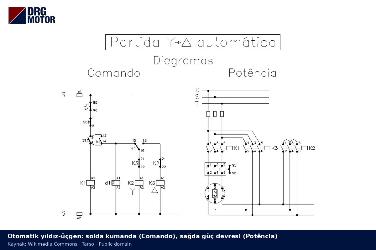
A star-delta control circuit is the low-current circuit that decides in which order the K1 main, K2 star and K3 delta contactors of the power circuit close. When the start button is pressed, K1 and K2 pull in together and the motor starts in star; when the KT timer runs out, K2 drops out and, after a short gap, K3 pulls in so the motor runs in delta. Interlocking contacts stop K2 and K3 from ever being energised at the same time.
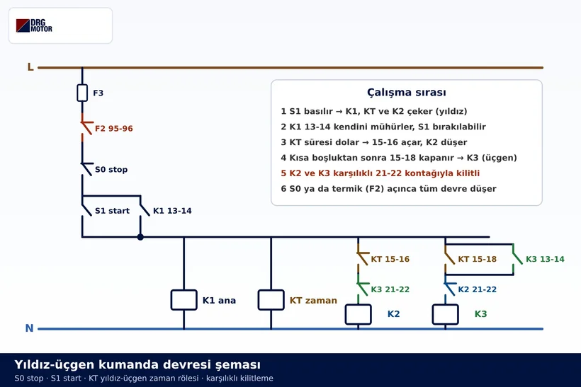
This article explains the logic of the diagram, meaning why each contact sits where it does. The diagrams explain the concept; the actual panel depends on the motor nameplate, the manufacturer's documentation and the judgement of qualified electrical personnel. DRG Motor is an electric motor manufacturer, supplier and seller; motors suitable for star-delta starting are found in the three-phase asynchronous electric motors family.
Why the Control Circuit Is Drawn Separately from the Power Circuit
A star-delta starter consists of two circuits. The power circuit shows the heavy conductors from the supply to the motor, the main contacts and the overload relay; the motor current flows here. The control circuit shows the coils and auxiliary contacts of the same contactors, and the current in it is only enough to feed the coils and the timer. When a coil is energised, the main contacts of that contactor close in the power circuit. Put simply, the control circuit makes the decision and the power circuit carries it out at the motor.
The current path through the main contacts, and which winding end is connected where in the star and delta stages, is covered in detail in the star-delta power circuit diagram article. Here we focus on the control side and only glance at the power circuit to see the result of each control step.
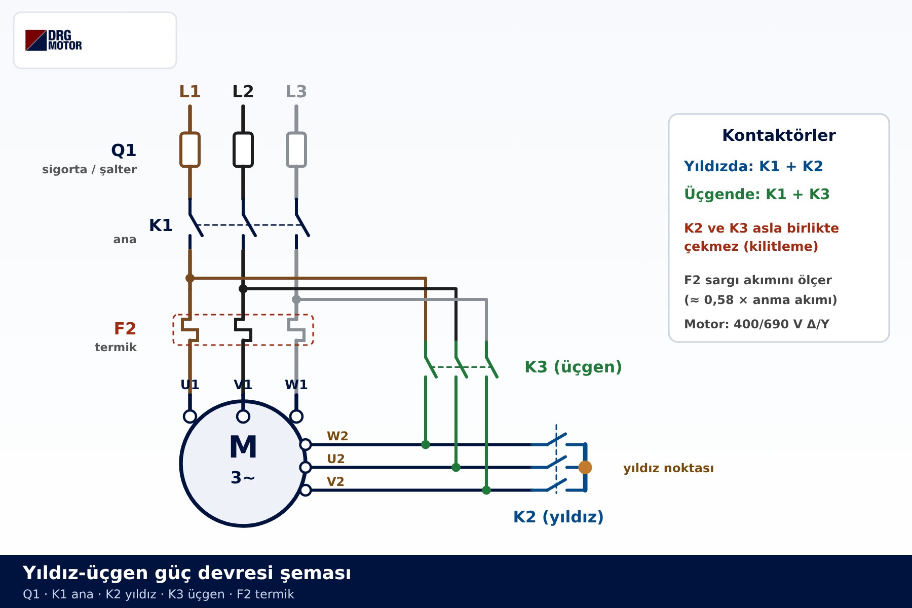
Below is another example with the control and power circuits drawn side by side. Portuguese headings: Comando = control, Potência = power.
Devices in the Diagram and What They Do
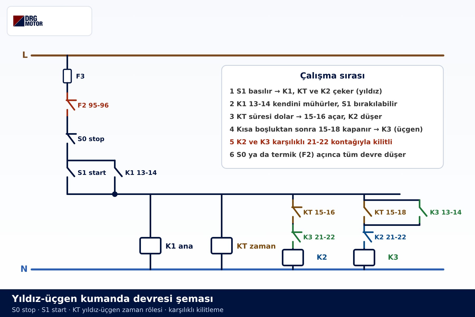
The control diagram reads like a ladder: the L (line) rail runs along the top and the N (neutral) rail along the bottom. Each rung is a branch leading to one coil, and that coil is energised only when every contact in its branch is closed.
| Device | Contact / coil | Role in the circuit |
|---|---|---|
| F3 | Control fuse | Protects the control circuit against short circuits |
| F2 | 95-96 (normally closed) | Cuts power to every coil when the overload relay trips |
| S0 | Stop, normally closed | Opens the circuit when pressed; the motor stops |
| Start button | Normally open | While pressed, feeds the K1, KT and K2 branches |
| K1 | Coil + 13-14 holding contact | Main contactor; keeps the circuit alive after start is released |
| KT | Coil + 15-16 and 15-18 | Times the star stage, then switches from star to delta |
| K2 | Coil + 21-22 interlock | Forms the star point; while closed it keeps the K3 branch open |
| K3 | Coil + 21-22 interlock, 13-14 hold | Forms the delta links; while closed it keeps the K2 branch open |
The contact numbers follow common marking practice: pairs ending in 1-2 are normally closed, pairs ending in 3-4 are normally open. On the timer, 15 is the common terminal, 16 the normally closed and 18 the normally open terminal. The device on site may use different terminal numbers; the manufacturer's wiring diagram always takes precedence.
The Series Chain: Fuse, Overload Contact and Stop Button
The first branch dropping from the L rail is the common input of the whole circuit. F3, F2 95-96 and S0 are in series here; if any one of them is open, no coil below can be energised. Choosing normally closed contacts for the overload and stop functions is a deliberate safety decision: if a wire to one of these contacts breaks or a terminal works loose, the circuit opens and the motor stops. With a normally open stop button, a broken wire would go unnoticed and the motor could not be stopped when it mattered.
Both ways of stopping live in this chain. When the operator presses S0, or the overload relay detects an overload and opens 95-96, the K1, KT, K2 and K3 coils all lose power at once. Because K1 drops out, the holding path is broken too, and the motor will only run again after the start button is pressed. That is also why the motor does not restart by itself after a power cut.
Click to see current electric motor prices and order nowSEE PRICES →
The Start Button and the Holding Contact
The start button is a normally open contact and conducts only while it is held down. Pressing it energises the common node below: the K1 and KT coils directly, the K2 coil through KT 15-16 and K3 21-22. The moment K1 pulls in, its own 13-14 auxiliary contact closes. This contact is wired in parallel with the start button, so current keeps flowing through 13-14 after the button is released. This is called the holding, latching or self-maintaining contact.
Without it, the motor would turn only while someone held the button. The holding contact latches the circuit onto itself, and the stop button is the only way to release that latch. When reading the diagram, note that the holding contact sits below the stop button; S0 always comes before the latch.
The KT Timer: Changing Over from Star to Delta
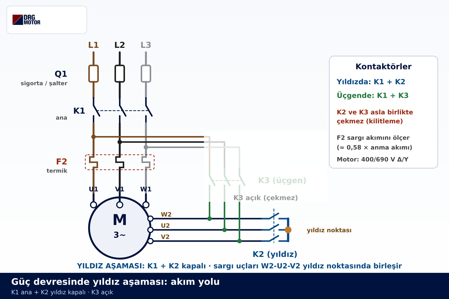
The KT coil is energised together with K1 and starts timing. During this time contact 15-16 stays closed and K2 is in; in the power circuit K1 and K2 are closed and the lower winding ends W2-U2-V2 are joined at the star point. Each winding sees the line voltage divided by √3, and the starting current and torque fall to about one third of what the same motor would draw starting directly in delta on the same supply.
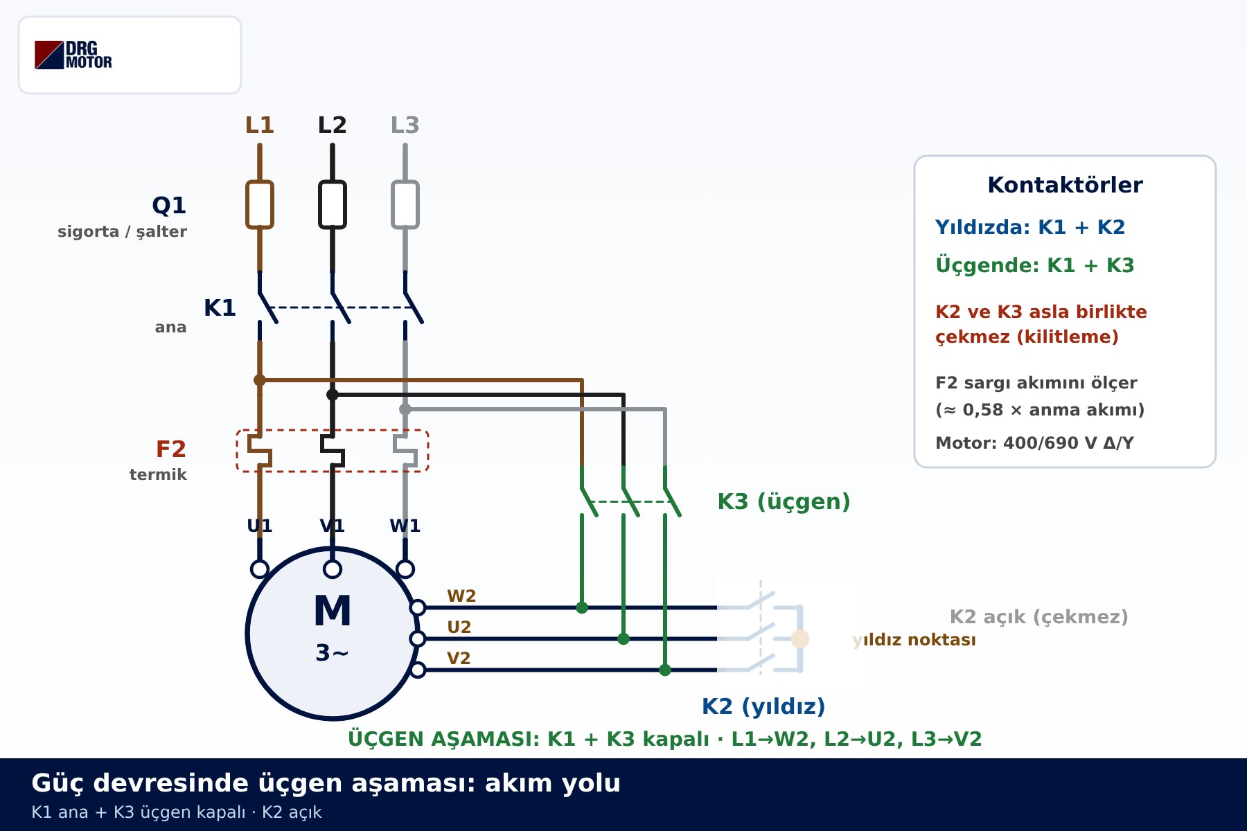
When the time is up, the timer opens 15-16; the K2 coil loses power and the star point is released. On timers made for star-delta duty, contact 15-18 does not close at once but after a short gap. This contact feeds the K3 coil through K2 21-22; K3 pulls in, the links U1–W2, V1–U2, W1–V2 are formed and each winding receives the full line voltage. Since K3's own 13-14 contact is in parallel with 15-18, K3 holds its own branch once it has closed.
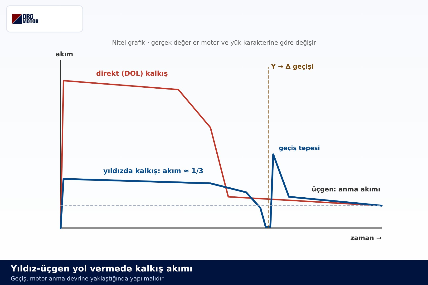
The length of the star stage is a goal rather than a fixed number: the motor should switch to delta only after it has come as close as possible to rated speed in star. How many seconds that takes depends on the load and the motor, and the setting is for a qualified electrician to judge. The chart below shows, qualitatively, how the current changes at changeover.
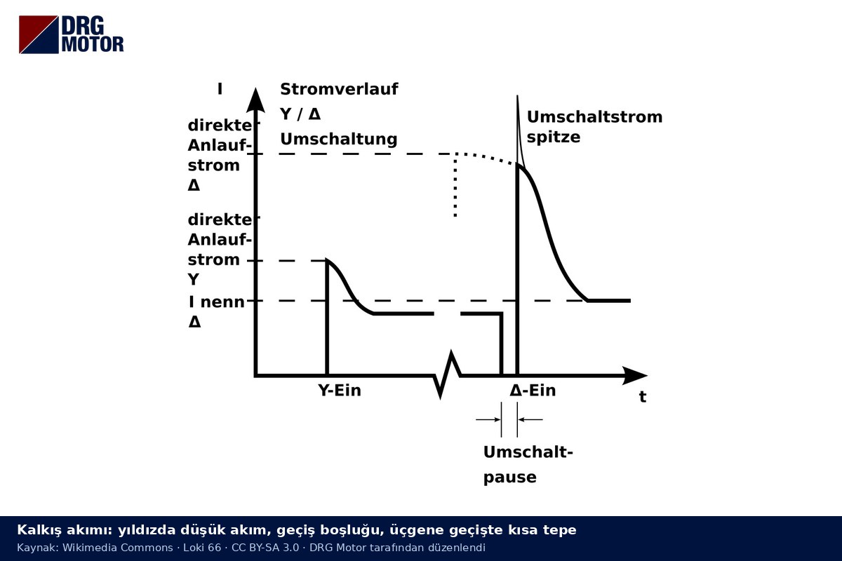
The curve below shows how current changes at switch-over. German labels: Y-Ein = star on, Δ-Ein = delta on, Umschaltpause = switch-over gap, Umschaltstromspitze = switch-over current peak.
Interlocking and the Changeover Gap
If K2 and K3 closed at the same time, the power circuit would see a phase-to-phase short circuit: K3 connects the two ends of each winding to different phases while K2 ties the same ends together at the star point. The control circuit guards against this in two separate layers.
- Electrical interlock: the K2 branch contains K3's 21-22 contact and the K3 branch contains K2's 21-22 contact. As long as one contactor is in, the other's coil branch stays open.
- Time gap: after opening 15-16, a star-delta timer waits briefly before closing 15-18. In that interval the main contacts of K2 open fully and the arc is extinguished.
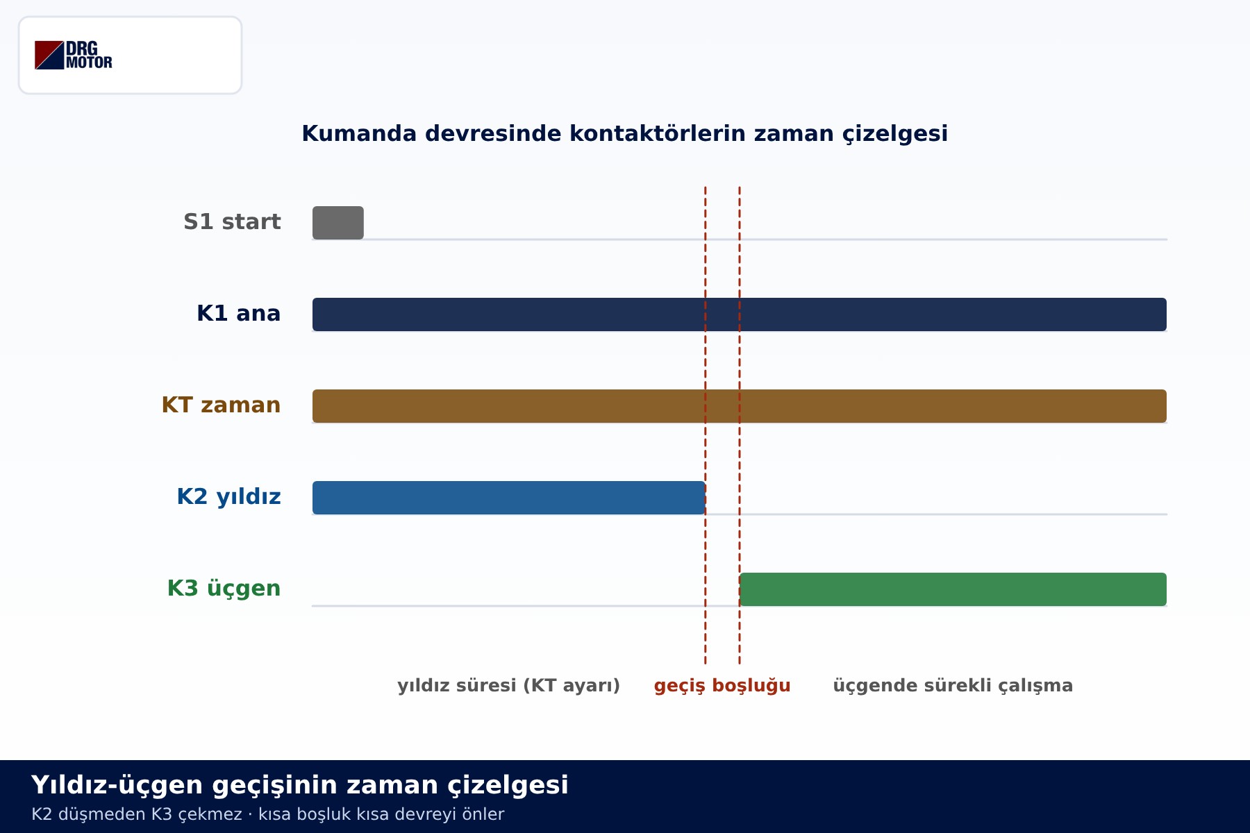
Many panels add a mechanical interlock between K2 and K3 as well. Together these measures make it much harder for a single fault, such as a welded contact, to turn into a short circuit. The timing chart shows the sequence on a horizontal time axis: K1 and KT are in from start to finish, K2 only during the star stage and K3 only after the gap.
Reading Common Faults from the Diagram
When troubleshooting, the control diagram works as a map. Linking a symptom to the branch that produces that behaviour often gives enough of a clue. The list below is a reasoning order, not a measuring procedure.
- Nothing pulls in when start is pressed: something in the series chain at the common input is open: F3, F2 95-96 or S0. If the overload relay has tripped, find out why before anything else.
- Runs while the button is held, stops on release: the holding path is not complete; suspect the K1 13-14 contact or its parallel connection across the start button.
- Motor stays in star and never goes to delta: the K3 branch is not being fed. Suspect, in turn, the KT 15-18 contact, the K2 21-22 interlock and the K3 coil; if K2 does not drop out, its 21-22 contact stays open too.
- Fuse blows at changeover: K3 may be closing before K2 has fully opened. Check the interlock contacts, whether the timer is a gap-type star-delta timer, and for welded contacts.
- Large current surge or overload trip at changeover: the motor may be switching before it has accelerated enough in star, or the load may be too heavy for the reduced star torque. Reviewing the star-delta vs soft starter comparison is worthwhile here.
- Motor runs hot or hums in delta: even with a correct control circuit, a motor rated 230/400 V cannot run in delta on a 400 V supply. For nameplate reading and link layout, see motor terminal star-delta connection and which kW motor is star or delta connected.
Overload and timer settings are outside the scope of this article. For the logic of contactor and overload currents see the 22 kW motor star-delta starting example. The basic concepts are covered in what is a star-delta connection, and all the diagrams are collected in the electric motor star-delta connection diagram guide and the star-delta wiring diagram PDF.
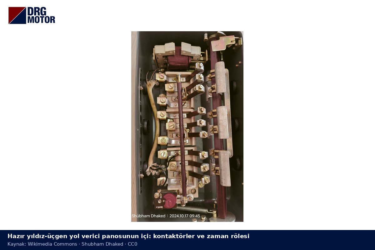
When troubleshooting, matching the diagram to the real panel layout helps; the photo shows a typical star-delta panel.
DRG Motors Suitable for Star-Delta Control
In the DRG range, motors of 4 kW and above are rated 400/690 V Δ/Y: they run in delta on a 400 V supply and are suitable for star-delta starting. Motors up to 3 kW are rated 230/400 V and run in star on a 400 V supply, so this method is not suitable for them. All models are IP55, insulation class F and IC411 cooled; contactors, overload relays and timers should be sourced from a switchgear supplier. You can filter by power and speed on the buy electric motors online page.
- DRG-112M-4 – 4 kW – 1500 rpm (synchronous) – 400/690 V Δ/Y – aluminium frame
- DRG-132M-4 – 7.5 kW – 1500 rpm (synchronous) – 400/690 V Δ/Y – aluminium frame
- DRG-160M-4 – 11 kW – 1500 rpm (synchronous) – 400/690 V Δ/Y – aluminium frame
- DRG-160L-4 – 15 kW – 1500 rpm (synchronous) – 400/690 V Δ/Y – cast iron frame
- DRG-180L-4 – 22 kW – 1500 rpm (synchronous) – 400/690 V Δ/Y – cast iron frame
- DRG-200L-4 – 30 kW – 1500 rpm (synchronous) – 400/690 V Δ/Y – cast iron frame
Click to see current prices for these motors and order nowSEE PRICES →
Frequently Asked Questions
Why is the holding contact in a star-delta control circuit taken from K1?
K1 is the only contactor that stays in from start to finish. K2 drops out after the star stage and K3 has not yet closed at start, so the contact that holds the circuit is K1's 13-14.
Will the circuit work without interlocking?
On paper the motor will still start, but if a contact welds or the timer changes over wrongly, K2 and K3 could close together and short the phases. The interlock contacts are there for exactly that case and should not be removed.
Can an ordinary on-delay timer be used for star-delta?
Some diagrams are built with the normally closed and normally open contacts of an on-delay timer, but those contacts change state at the same instant. A star-delta timer deliberately leaves a gap between its two contacts. Which one to use depends on the manufacturer's documentation and the judgement of a qualified electrician.
Will the motor restart by itself after a power cut?
Not with this circuit. When power is lost K1 drops out and the latch is broken; when power returns, the start button has to be pressed again.





