 English
 Le français
 Türkçe

Because in a flange connection it is the spigot, not the bolts, that locates the motor shaft on the machine axis. Even if the bolt holes match exactly, a different spigot diameter means the motor either will not enter its recess or sits in it with play, and the shaft runs off-centre relative to the machine axis.
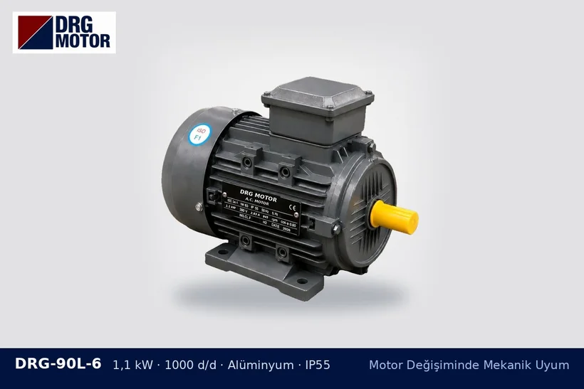
Why don't the bolts centre the motor?
Flange holes are made somewhat larger than the bolt; this clearance, which eases assembly, also allows the motor to shift sideways. The spigot and the recess in the machine, by contrast, form a close-tolerance fit. Thanks to this fit, a pump impeller turns without rubbing on its casing, and the seal and bearing at a gearbox input are loaded evenly.
Examples of standard flange sizes
On IEC flanges with clearance holes (FF type), the flange code refers to the bolt circle diameter, while the spigot diameter is a separate value:
| Flange code | Bolt circle (mm) | Spigot diameter (mm) | Typical frame |
|---|---|---|---|
| FF165 | 165 | 130 | 80 / 90 |
| FF215 | 215 | 180 | 100 / 112 |
| FF265 | 265 | 230 | 132 |
Small flanges (FT type, with tapped holes) have different values; two different flange options may exist for the same frame.
How to measure
- Measure the outside diameter of the spigot with a caliper at no fewer than two points.
- Note the height of the spigot (how far it projects); if it is deeper than the recess in the machine, the flange face will not seat.
- Record the bolt circle diameter between the centres of opposite holes, together with the number and type of holes.
- Also measure the recess diameter on the machine side; a worn recess will make the new motor sit off-centre as well.
Signs of incorrect centring
Vibration, rapid wear of the coupling element, seal leakage and bearing noise are typical signs. After comparing the dimensions with the DRG technical drawings, you can review the motor options used in gearbox drives; whether the flange type is available on the model should be confirmed before ordering.