 English
 Le français
 Türkçe




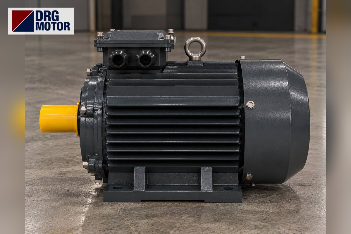

Alternating operation in a two-pump system means the two pumps take turns: P1 runs on one demand, P2 on the next. Running hours are shared between the motors, the idle pump does not sit still long enough to seize, and if one pump’s overload relay trips the other takes over. On high demand, a second pressure or level contact runs both pumps together, with a short delay between them.
Safety notice: This content is for technical information only. Wiring, measurement and commissioning must be carried out by qualified electrical personnel, following lock-out and verification of de-energised state, and in line with the motor and device manufacturer's documentation.
This article draws three control schemes separately: duty/standby, alternating (with an alternating relay) and both pumps on high demand. The diagrams are examples; terminal names vary by device and the device’s own wiring diagram prevails.
Three operating modes: duty/standby, alternating, both together
In booster sets, sewage lifting stations, circulation loops and boiler rooms, two pumps are often connected in parallel on the same pipework. The panel can manage them in three ways:
- Duty/standby: P1 runs on every demand. P2 only starts when P1’s protection trips. Simple, but P2 may stay idle for months while P1 wears out.
- Alternating: the next pump in line runs on each new demand. Running hours are roughly equal and both pumps turn regularly. Standby backup is kept.
- Both on high demand: when one pump cannot keep up, a second-stage contact (for example a second pressure switch set lower, or a second level contact) also starts the pump that is not in line.
In practice the three are combined in one panel. The diagrams below build that combination step by step.
Power circuit: separate protection for each pump
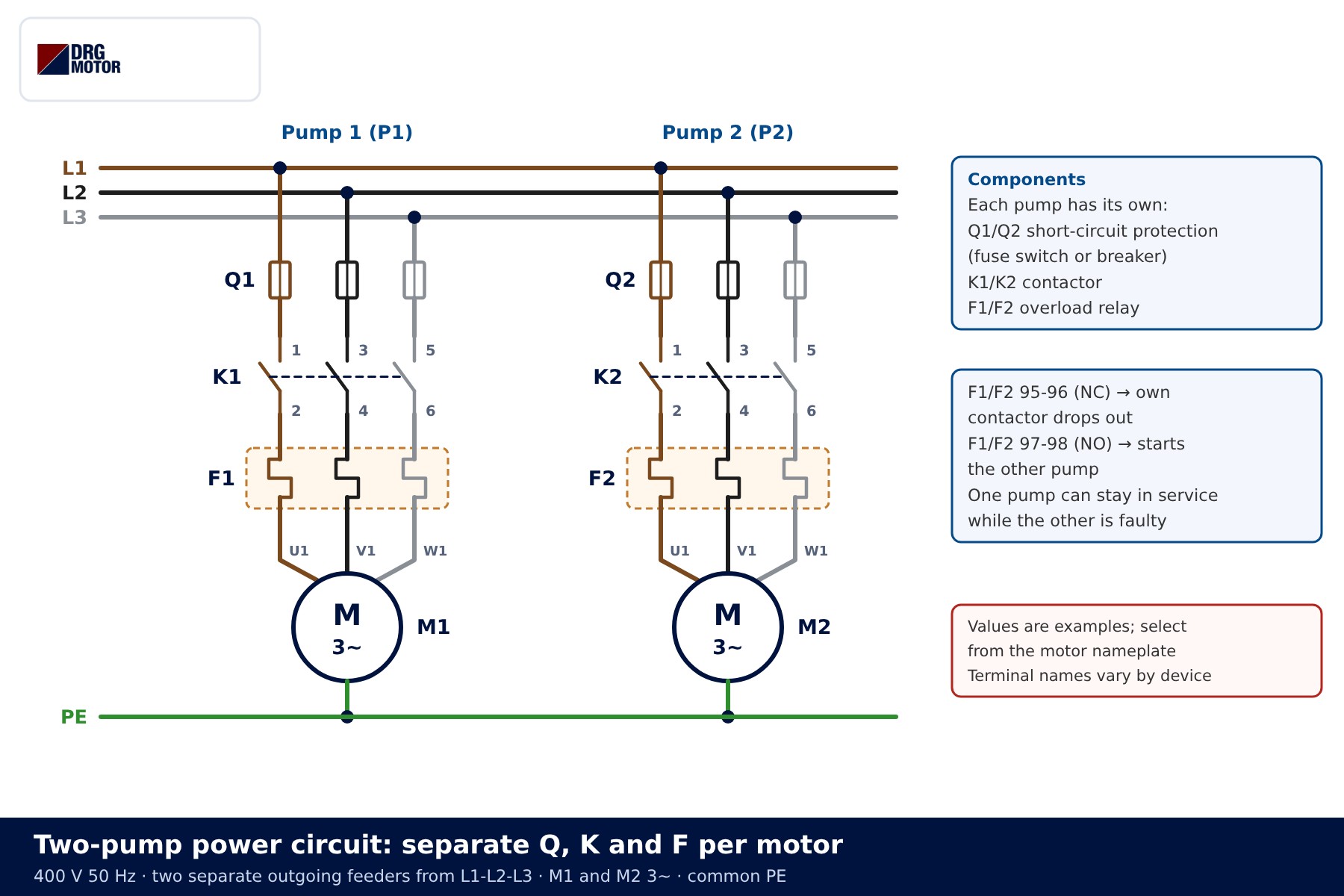
Both pumps are fed from common busbars, but each outgoing feeder is independent: Q1 short-circuit protection, K1 contactor, F1 overload relay and M1 motor for P1; Q2, K2, F2 and M2 for P2. A single shared protection would defeat the main benefit of the scheme, which is that one pump can run while the other is faulty.
| Component | Terminals | Function |
|---|---|---|
| Q1, Q2 | 1-2 / 3-4 / 5-6 | Short-circuit protection of each motor feeder |
| K1, K2 | A1-A2, main poles, 21-22 NC | Connect the pump to the supply; NC contact for interlocking |
| F1, F2 overload relay | 95-96 NC, 97-98 NO | 95-96 drops its own contactor, 97-98 calls the other pump |
| B1 | 13-14 NO | First-stage demand: closes when pressure or level falls |
| B2 | 23-24 NO | Second-stage (high demand) contact |
| KA alternating relay | A1-A2, Y1, 11-14, 21-24 | Changes output on each demand |
| KT timer | A1-A2, 17-18, 27-28 | Brings in the second pump with a delay |
Overload setting, contactor and fuse size are chosen from each motor’s own nameplate current; even with two identical pumps, size each feeder separately. For a first estimate use the overload, fuse and contactor selection tool, and the motor cable size calculator for the cables.
Duty/standby control circuit
The simplest backup scheme uses both auxiliary contacts of the overload relay. When the B1 demand contact closes, current flows through F1 95-96 and K2 21-22 to the K1 coil and P1 runs. The P2 branch contains the F1 97-98 NO contact, so P2 is normally de-energised.
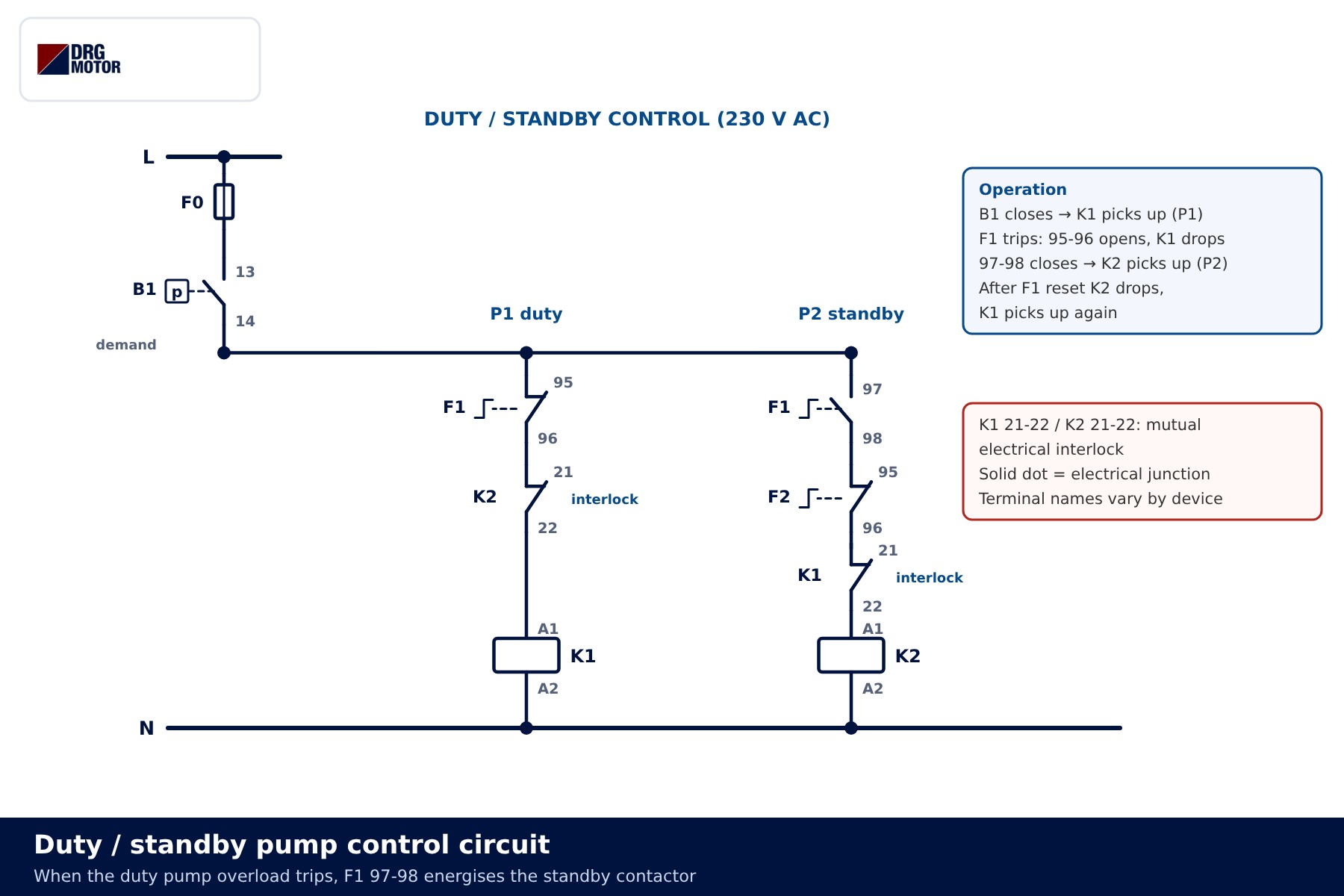
- Demand arrives: B1 closes, K1 picks up, P1 runs.
- F1 trips: 95-96 opens and K1 drops out; at the same moment 97-98 closes and feeds the K2 coil. P2 runs.
- Demand ends: B1 opens and whichever pump is running stops.
- F1 is reset: 97-98 opens, K2 drops out; if demand is present, K1 picks up again.
K1 21-22 and K2 21-22 form a mutual electrical interlock, just as in a forward-reverse circuit: in duty/standby the two contactors should never be closed together. Always find out why the overload tripped; the standby pump only buys time. Typical causes are listed in why an electric motor trips its overload.
Click to see current electric motor prices and order nowSEE PRICES →
Alternating operation with an alternating relay
In the alternating scheme an alternating relay (KA) keeps track of the order. Its supply terminals (A1-A2) are permanently energised; the B1 demand contact feeds both the KA demand input (Y1) and the common of KA’s two output contacts. On each demand KA closes only one output: 11-14 feeds K1, 21-24 feeds K2. When the demand ends, the relay changes the order.
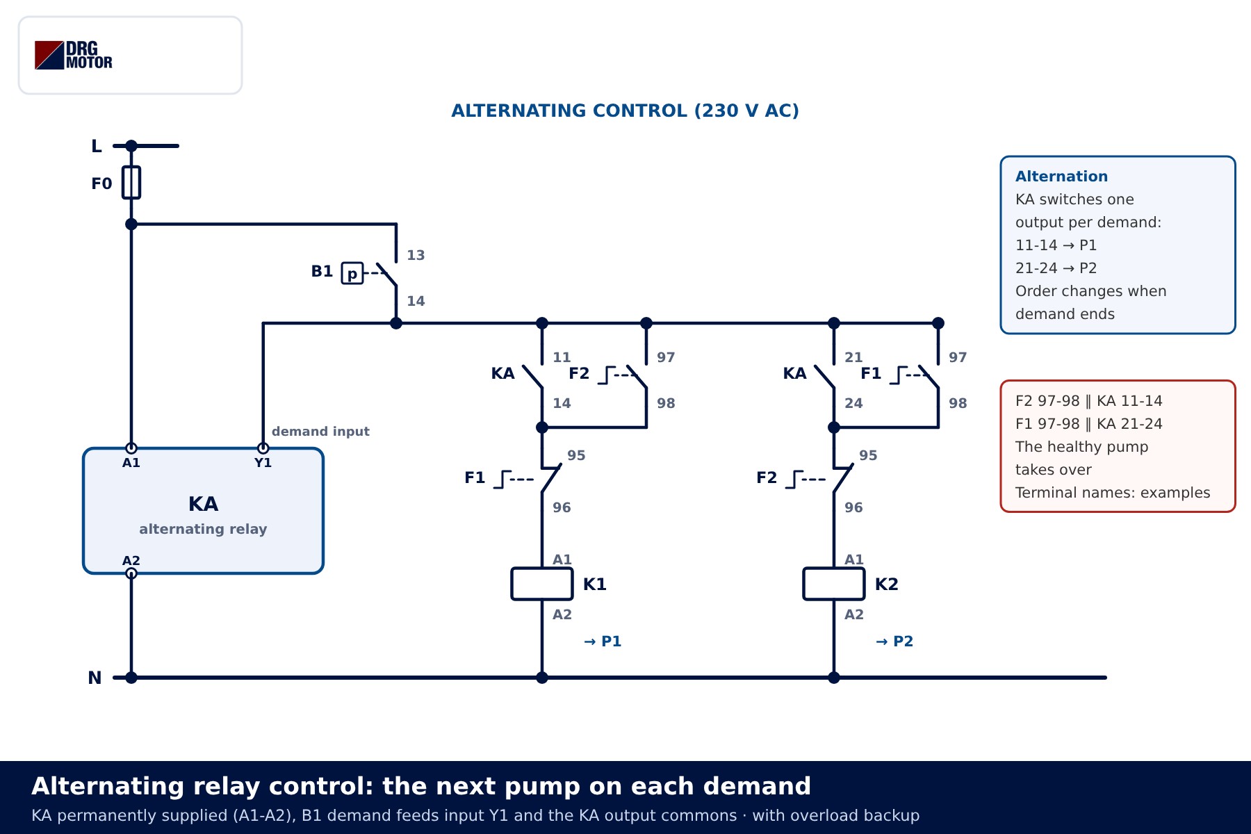
Backup is kept here too: F2 97-98 is wired in parallel with KA 11-14, and F1 97-98 in parallel with KA 21-24. If it is P2’s turn but F2 has tripped, the demand is passed to K1 through F2 97-98. Each branch also has its own overload 95-96 contact in series, so a faulty pump cannot be started by any path.
📄 Download Wiring Diagram PDF A4 printable PDF of the diagrams and tables (no sign-up)
What happens inside an alternating relay?
Conceptually, an alternating relay is an impulse relay (a toggle or T flip-flop). The moment the demand contact opens – the falling edge – Q changes state. With Q = 0 the demand is routed to K1, with Q = 1 to K2. It matters that the order changes when demand ends rather than while a pump is running; otherwise the running pump would stop mid-demand and the other would start.
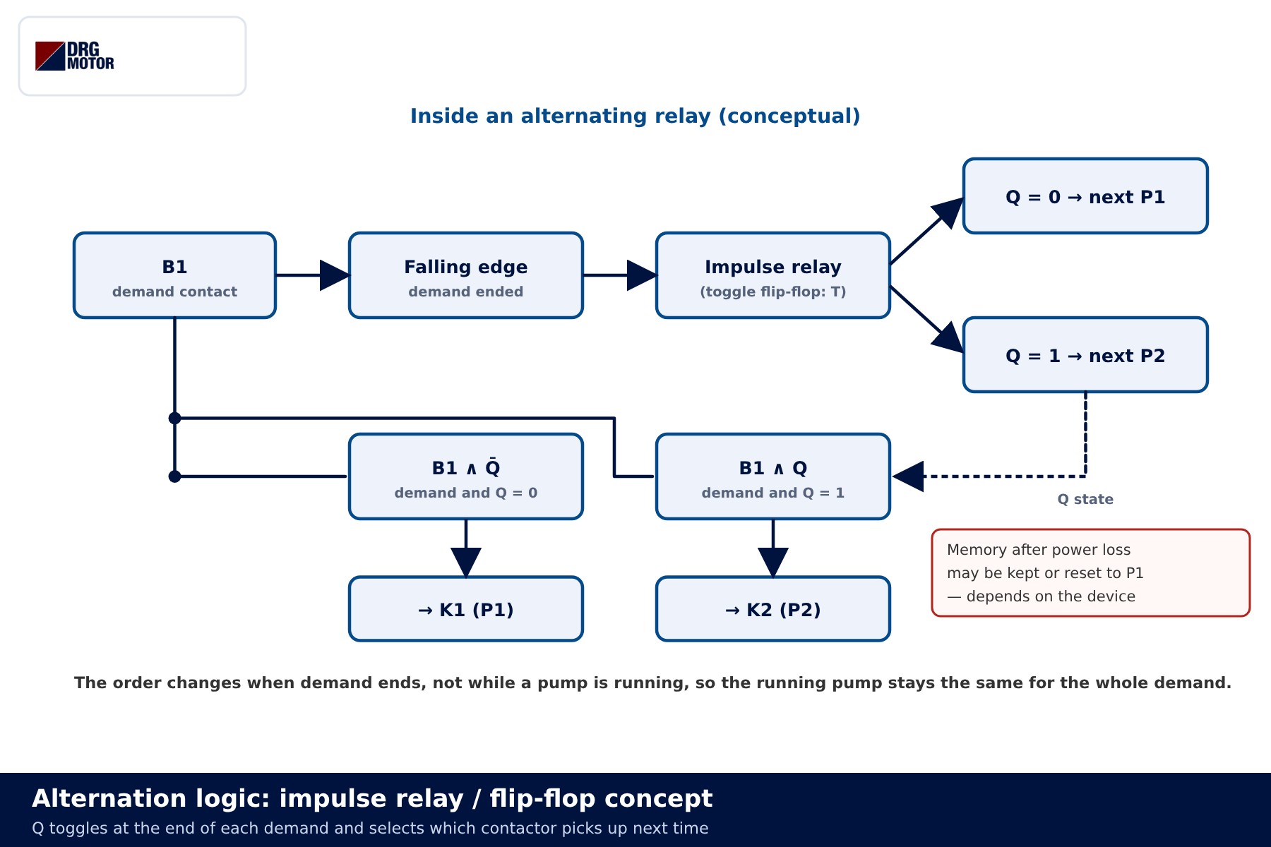
The same logic can be built with an impulse relay and two auxiliary relays, or with a small programmable relay. Whether the order survives a power cut depends on the device, so check it during commissioning.
Both pumps on high demand, with a staggered start
If demand exceeds one pump’s capacity, the second-stage contact B2 closes and energises timer KT. Its on-delay contacts 17-18 and 27-28 are added in parallel in both pump branches. When the delay expires, the pump that is not in line starts as well. When B2 opens, KT drops out and the second pump stops; the first one keeps running until B1 opens.
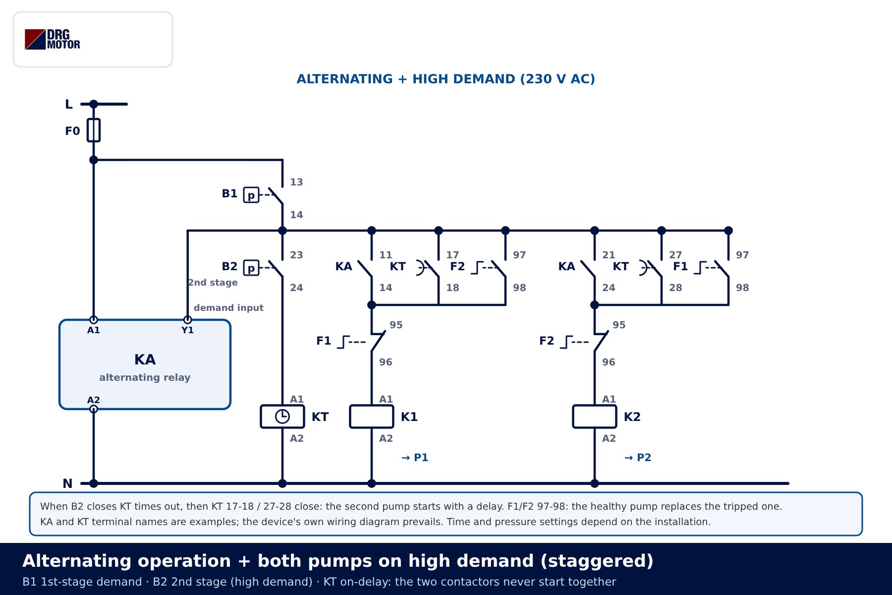
The KT delay ensures that K1 and K2 never start at the same instant. Two direct-on-line starts at once add their inrush currents, causing a voltage dip and unnecessary stress on the main protection. Even when power returns with B1 and B2 both closed, the first pump starts immediately and the second only after the KT delay. Choose the delay long enough for the first pump to finish accelerating; the exact value depends on the installation and the motor nameplate. Because both pumps are meant to run together here, no mutual interlock is fitted between K1 and K2.
State table and timing diagram
The table shows one moment per row. The “Next” column is the pump that will run on the next demand.
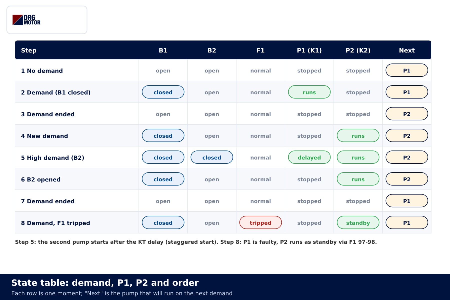
| State | P1 | P2 | Next |
|---|---|---|---|
| No demand | stopped | stopped | P1 |
| Demand (B1) | runs | stopped | P1 → P2 when demand ends |
| New demand | stopped | runs | P2 → P1 when demand ends |
| High demand (B1 + B2) | runs after KT | runs | P2 |
| Demand, F1 tripped | stopped | runs as standby | P1 |
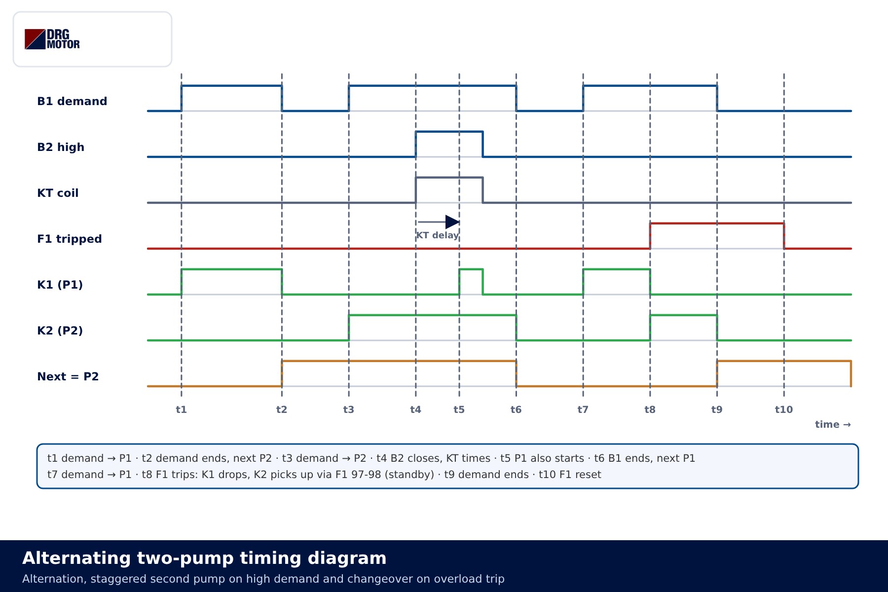
In the diagram, t4–t5 is the KT delay: the second pump does not start the moment B2 closes but when the delay has elapsed. At t8 F1 trips, K1 drops out and K2 picks up through F1 97-98.
Common wiring mistakes
| Symptom | Likely cause |
|---|---|
| The same pump always runs | Demand wired straight to the K1 branch instead of the KA input, or the KA supply taken from the demand contact |
| Pumps change over mid-demand | Changeover tied to a timer instead of the end of demand |
| Standby pump does not start on overload trip | 95-96 used instead of 97-98, or 97-98 wired into the wrong branch |
| A tripped pump starts again | Its own overload 95-96 contact is not in series in its branch |
| Both pumps start at the same instant | A plain contact used instead of KT, or the wrong delay type |
| Pumps start and stop too often | Narrow pressure band, vessel pre-charge or check-valve problem |
Frequent starting is what wears a motor winding fastest. See why booster pump motors burn out for the causes, and this FAQ answer for a checklist when a booster motor starts too often.
Selection examples
- Apartment booster set, 2 × 2.2 kW: alternating plus standby is enough. One pump usually covers the demand; a B2 stage may not be needed.
- Hotel or residential complex, 2 × 5.5 kW: a B2 stage with KT staggered start is recommended for evening peaks. Contactor and overload sizes are set for each motor separately.
- Sewage lifting station, 2 × 4 kW: demand comes from level contacts; the upper level calls the second pump. A high-level alarm should be given by a separate contact.
Where larger motors are not started direct-on-line, each branch gets its own star-delta control circuit; the alternation logic is then applied to the start input of each starter instead of directly to K1 and K2. For contactor utilisation categories, see motor panel contactor selection.
📄 Download Wiring Diagram PDF A4 printable PDF of the diagrams and tables (no sign-up)
Send a photo of your current motor nameplate and we will find the suitable DRG model together.Send on WhatsApp
DRG three-phase motors for pump systems
DRG Motor is an electric motor manufacturer, supplier and seller. Below are some three-phase IEC motors in the 3000 rpm class commonly used on centrifugal pumps. Alternating relays, timers, contactors, overload relays and pressure switches are not sold by DRG; please contact your panel component supplier for those. Other power and speed options are listed on the three-phase asynchronous electric motors page and in the online store.
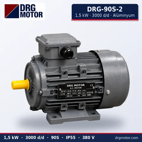
1.5 kW Three-Phase Motor 3000 rpm – DRG-90S-2 Aluminium
- 1.5 kW · 3000 rpm (2 poles)
- Aluminium frame · IEC 90S
- Mounting: B3 · B5 · B14 · B35
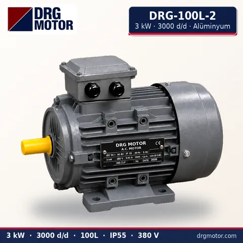
3 kW Three-Phase Motor 3000 rpm – DRG-100L-2 Aluminium
- 3 kW · 3000 rpm (2 poles)
- Aluminium frame · IEC 100L
- Mounting: B3 · B5 · B14 · B35
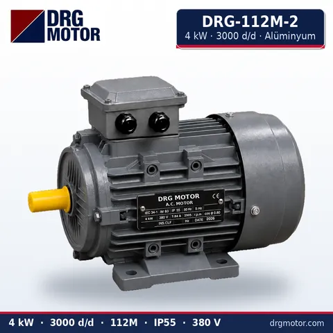
4 kW Three-Phase Motor 3000 rpm – DRG-112M-2 Aluminium
- 4 kW · 3000 rpm (2 poles)
- Aluminium frame · IEC 112M
- Mounting: B3 · B5 · B14 · B35
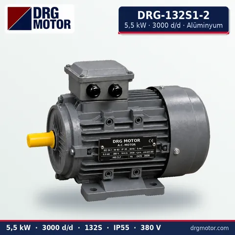
5.5 kW Three-Phase Motor 3000 rpm – DRG-132S1-2 Aluminium
- 5.5 kW · 3000 rpm (2 poles)
- Aluminium frame · IEC 132S
- Mounting: B3 · B5 · B14 · B35
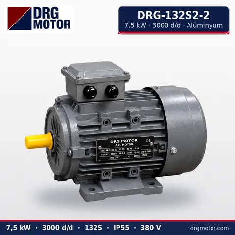
7.5 kW Three-Phase Motor 3000 rpm – DRG-132S2-2 Aluminium
- 7.5 kW · 3000 rpm (2 poles)
- Aluminium frame · IEC 132S
- Mounting: B3 · B5 · B14 · B35
Click to see current prices for these motors and order nowSEE PRICES →
Frequently asked questions
Does alternating operation extend pump life?
It splits running hours between the two pumps and stops the idle pump from standing still for long periods. Seal, bearing and impeller wear is spread over time. If the pumps start too often, fix the cause in the system first.
Can a timer be used instead of an alternating relay?
It can, but extra interlocking is needed so that the order never changes mid-demand. An impulse or alternating relay that toggles at the end of demand is the simpler solution.
Why should the two pumps not start together on high demand?
Overlapping inrush currents cause a voltage dip and put needless stress on the supply protection. A timer such as KT starts the second pump after a short delay.
Why is there a mutual interlock in duty/standby but not in alternating mode?
In duty/standby the two pumps are never meant to run together, and the interlock guarantees it. In an alternating scheme with a high-demand stage, running both pumps together is intentional.
Is the order lost after a power cut?
That depends on the device. Some alternating relays store the last state, others restart with P1. In both cases backup and the staggered start keep working.





