English
 Le français
 Türkçe




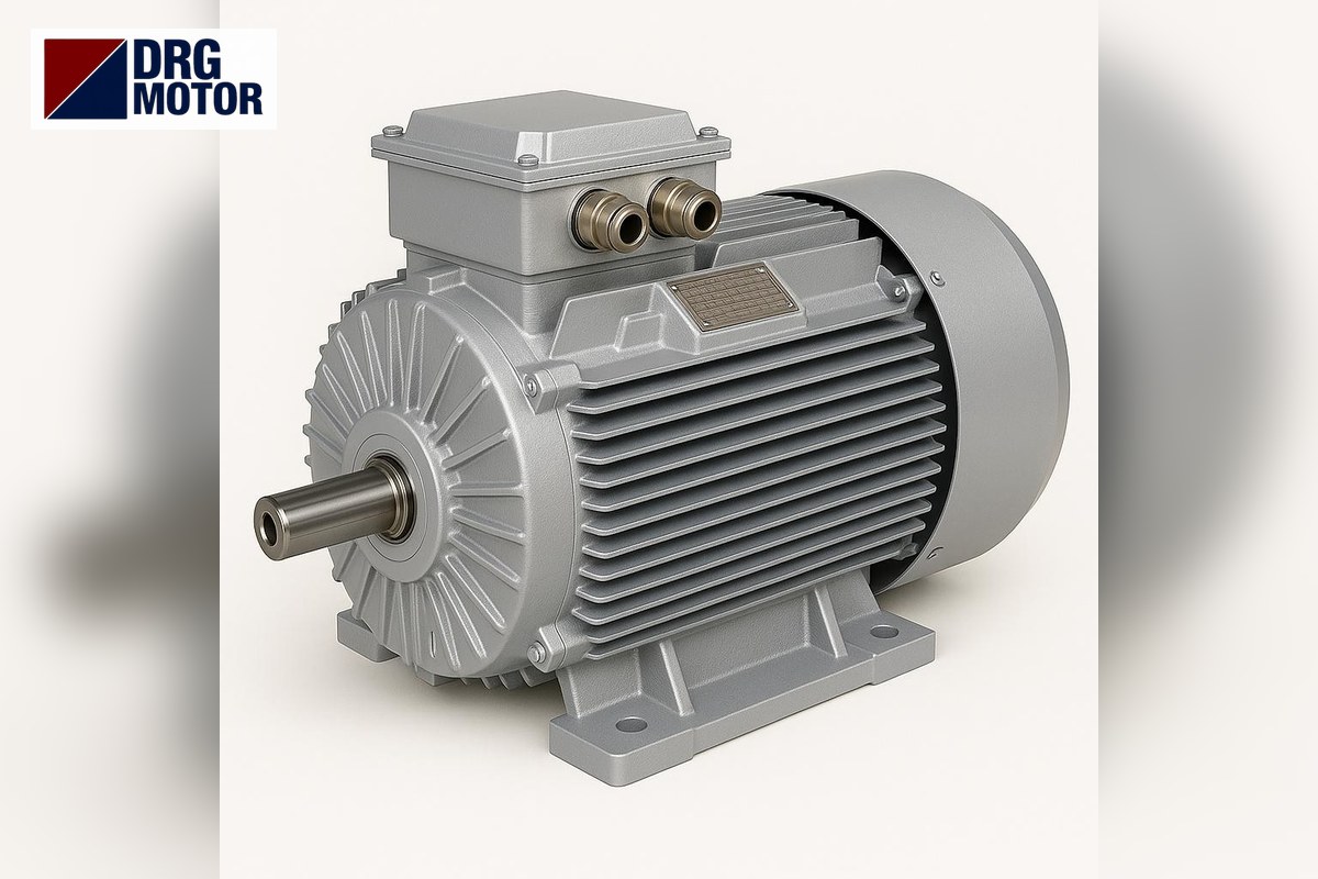

A booster pump (hydrophore) motor usually burns out for one of four reasons: starting and stopping several times a minute (a pressure tank that has lost its pre-charge or has a torn membrane, or a badly set pressure switch), phase loss or low voltage, water leaking from the mechanical seal into the motor, and the pump loading the motor above its nameplate. Dry running mostly destroys the seal first and burns the motor indirectly, through the water that leaks afterwards. For example, a 2.2 kW two-pole three-phase motor draws 4.35 A at 400 V, but at every start it sees 7.6 times that, roughly 33.1 A; a motor that starts dozens of times an hour never gets the chance to cool its winding.
Safety first: removing the burnt motor, measuring the winding and voltage, and connecting the new motor must be done by a qualified electrician. Do not touch the pump or the terminal box before the panel is switched off and locked out and the water pressure in the tank is released. This article helps you find the cause and choose a replacement of the same dimensions; you can filter every suitable model by frame, power and speed on the Buy Electric Motors Online page.
If you are not sure the motor is really burnt, first follow the burnt motor check with winding measurements; the sections below cover what to do once a burnt winding is confirmed.
What burns a booster pump motor: symptoms and remedies
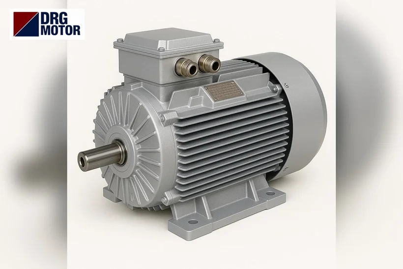
If you do not find what killed the old motor before fitting a new one, the new one will go the same way. The table below lists the six most common causes, the trace each leaves on the motor and installation, and the lasting remedy.
| Cause | Symptom | Remedy |
|---|---|---|
| Frequent starting and stopping | The pump runs for a few seconds when a tap is opened, stops and starts again; the tank feels empty, water comes out of the air valve | Check the tank pre-charge and membrane, widen the gap between the cut-in and cut-out pressure of the switch |
| Dry running | Hot seal area, smell of rubber, then water dripping towards the motor | Float switch, level relay or dry-run protection; cut the pump when the reservoir is low |
| Phase loss | The motor hums, fails to start or turns slowly; one of the three windings is intact, two are blackened | Phase-failure relay and a correctly set motor protection breaker; measure all three phases on fused lines |
| Low voltage | Current above the nameplate value, overload trips especially in the evening | Measure terminal voltage under load; upsize long, thin cables with a cable-size calculation |
| Moisture / seal leak | Rusty bearing, water marks in the terminal box, low insulation resistance | Replace the seal, keep the motor drain holes open, protect the motor from splashing water |
| Overcurrent (mechanical load) | Current rises when the pump runs with a fully open valve at low pressure; impeller rubbing or clogged | Check the pump duty point, inspect the impeller and bearings, redo the power calculation if needed |
You can read why a motor heats up within minutes on two phases in why phase loss is dangerous for a motor; what matters here is never commissioning the new motor without protection.
Frequent starting: pressure switch and tank pre-charge
Short cycling is the quietest way to kill a booster pump motor. The pressure tank provides an air cushion so that the pump does not start every time a small amount of water is drawn. Over time the pre-charge on the air side drops, or the membrane tears and the tank fills completely with water. From then on, every time a tap opens the pressure collapses, the switch starts the pump, pressure rises within seconds, the pump stops and the cycle repeats.
At every start the motor draws several times its rated current; for the DRG-90L-2 the nameplate ratio is 7.6, about 33.1 A at 400 V. Even if short, this current heats the winding; when the pauses are too short the heat accumulates and the insulation ages. Check the following:
- With the pump stopped and the tank drained, measure the pre-charge at the tank air valve with a gauge; compare it with the value on the tank label and in the pump manual.
- If water comes out of the air valve, the membrane is torn; do not fit a new motor before the tank or membrane is replaced.
- If the difference (differential) between cut-in and cut-out pressure on the switch is set too narrow, widen it.
- A dripping tap, a leaking check valve or a cistern makes the pump start at night too; find it with the meter and by listening.
Check the pump power: kW from flow and head
Buying the same power as the burnt motor is usually right, but if the motor burnt from overload you first need to see what the pump really demands. The basic relation for the pump shaft power is P = ρ·g·Q·H / ηp, where ρ is water density (1000 kg/m³), g is gravitational acceleration (9.81 m/s²), Q is flow (m³/s), H is head (m) and ηp is the pump efficiency.
Example (assumptions stated): 6 m³ of water per hour, 50 m head and ηp = 0.55 for the pump. Hydraulic power is 1000 × 9.81 × (6/3600) × 50 ≈ 0.82 kW and shaft power 0.82 / 0.55 ≈ 1.49 kW. Allowing a 1.15 factor for flow variation and voltage drop, the demand is ≈ 1.71 kW, so the next standard size, 2.2 kW, is chosen. A 1.5 kW motor would be marginal at this point and would be overloaded when the pump delivers a lot of water at low pressure. The definitive value is the pump’s own curve and label; you can repeat the calculation with the pump and fan motor power calculator.
Booster pump motors are generally two-pole and turn at about 2900 rpm; 0.75–4 kW is common in houses and apartment buildings. Single-phase versus three-phase is a separate decision covered in single-phase or three-phase motor for a booster set; here we assume a three-phase motor is replaced by a three-phase motor.
Matching the new motor from the nameplate: power, speed, flange and shaft
If the burnt motor’s nameplate is still legible, most of the order comes from it. If not, measure. There are five items to match:
- Power (kW): the motor power on the pump label or the calculation above. Do not go one size smaller.
- Speed: if the pump is designed for two poles, a four-pole motor will drastically reduce pressure. For example, the DRG-801-2 turns at 2880 rpm and the DRG-112M-2 at 2905 rpm.
- Voltage and connection: models up to 3 kW are 230/400 V and are star-connected on a 400 V supply; the DRG-112M-2 is 400/690 V and is delta-connected at 400 V.
- Flange: on a motor seated on the pump casing, the flange outer diameter P, bolt circle M and spigot diameter N must match the old one.
- Shaft diameter and length (D×E): the impeller or coupling sits on this shaft; even 1 mm difference prevents assembly.
The B5 flange dimensions below come from the DRG catalogue (mm). Frames 80 and 90 share the same flange but have different shafts, so never order by the flange alone.
| IEC frame | Flange outer diameter P | Bolt circle M | Spigot N | Hole diameter S | Shaft D×E |
|---|---|---|---|---|---|
| 80 | 200 | 165 | 130 | 12 | 19×40 |
| 90S | 200 | 165 | 130 | 12 | 24×50 |
| 90L | 200 | 165 | 130 | 12 | 24×50 |
| 100L | 250 | 215 | 180 | 14.5 | 28×60 |
| 112M | 250 | 215 | 180 | 14.5 | 28×60 |
Caution: on some close-coupled booster pumps the impeller is mounted directly on the motor shaft, and the shaft has a dimension specific to the pump maker. Measure the old shaft’s diameter, length and keyway with a caliper; if it differs from the standard IEC shaft, an adapter with a coupling is needed between pump and motor. For full dimensions see the DRG motor technical drawings page.
Two-pole DRG motors for booster pumps: current and shaft table
All values in the table are DRG catalogue data; the starting current column is the 400 V rated current multiplied by the nameplate Is/In ratio. Pick the power closest to the pump, then verify the shaft and flange against the table above.
| Model | kW | Speed (rpm) | Frame | Current 400 V (A) | Current 380 V (A) | Shaft D×E (mm) | Starting current 400 V (A, calculated) |
|---|---|---|---|---|---|---|---|
| DRG-801-2 | 0.75 | 2880 | 80 aluminium | 1.64 | 1.72 | 19×40 | 11.5 |
| DRG-802-2 | 1.1 | 2880 | 80 aluminium | 2.31 | 2.43 | 19×40 | 16.9 |
| DRG-90S-2 | 1.5 | 2895 | 90S aluminium | 3.06 | 3.22 | 24×50 | 23.3 |
| DRG-90L-2 | 2.2 | 2895 | 90L aluminium | 4.35 | 4.58 | 24×50 | 33.1 |
| DRG-100L-2 | 3 | 2895 | 100L aluminium | 5.71 | 6.02 | 28×60 | 44.5 |
| DRG-112M-2 | 4 | 2905 | 112M aluminium | 7.45 | 7.84 | 28×60 | 61.8 |
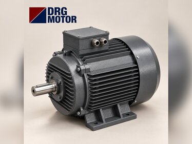
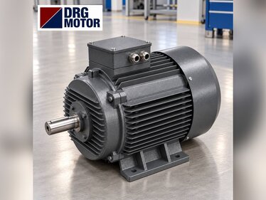
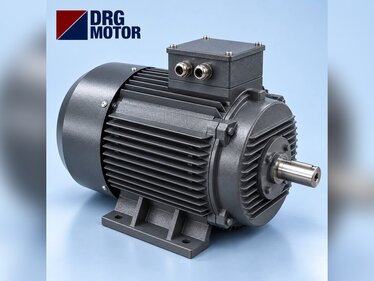
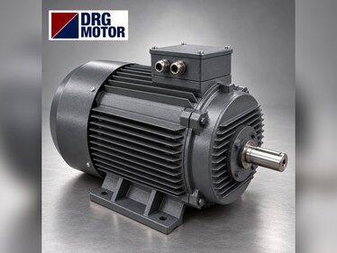
The aluminium frame is light and easy to handle on top of a pump; cast iron versions of the same models are also in the store. If the pump room is damp, position the terminal box facing down or sideways and make sure the cable gland is tight.
Motor protection breaker setting and commissioning checklist
If the new motor runs in the same unprotected circuit that burnt the old one, the result repeats. The current setting of the motor protection breaker (or thermal overload relay) is the nameplate current at the supply voltage and must not be set above it. For the DRG-90L-2 that is 4.35 A on a 400 V supply and 4.58 A on 380 V; for the 1.5 kW DRG-90S-2 it is 3.06 A at 400 V. When it trips, look for the cause instead of raising the setting. You can check breaker and contactor sizes with the overload, fuse and contactor selection tool.
- Measure the voltage of all three phases at the panel input and at the motor terminals; if there is a clear difference between phases, fix the supply first.
- Fit the terminal links for the nameplate voltage (star/delta) and tighten the nuts.
- Run the motor briefly before coupling it and compare the direction of rotation with the arrow on the pump casing.
- Never run the pump before the pump and suction line are filled with water; dry running ruins the seal in the first minute.
- While running, measure the current of all three phases with a clamp meter; it must be below the nameplate current and the phases close to each other.
- Check the tank pre-charge and the pressure switch setting; watch how many seconds the pump runs when one tap is opened.
- Test the phase-failure relay and the dry-run protection with their test buttons.
Motors in this power range
The two-pole models most often needed when replacing a booster pump motor:
- DRG-90S-2 – 1.5 kW – 2895 rpm – 90S aluminium
- DRG-90L-2 – 2.2 kW – 2895 rpm – 90L aluminium
- DRG-100L-2 – 3 kW – 2895 rpm – 100L aluminium
- DRG-112M-2 – 4 kW – 2905 rpm – 112M aluminium
Click to see current prices and order these motors nowSEE PRICES →
Frequently Asked Questions
Why does my booster pump motor keep tripping the overload?
The most common causes are phase imbalance, low voltage, a wrong overload setting (below the nameplate current) and the pump overloading the motor by delivering a lot of water at low pressure. Measure the current of all three phases; if it is above the nameplate value there is a mechanical or electrical problem, and raising the setting is not the fix.
What speed should a booster pump motor have?
Most booster pumps run with a two-pole motor at about 2900 rpm. On DRG two-pole models the rated speed is between 2880 and 2905 rpm depending on power. If the pump is built for two poles, fitting a four-pole motor seriously reduces pressure and flow.
How many amps does a 2.2 kW booster pump motor draw?
The DRG-90L-2 (2.2 kW, two-pole) draws 4.35 A at 400 V and 4.58 A at 380 V. At start-up this rises to 7.6 times that, about 33.1 A at 400 V, which is why frequent starts heat the motor.
Can a burnt booster pump motor be replaced with another make?
Yes, if power, speed, voltage, flange dimensions (P, M, N) and shaft (D×E) are the same. IEC standard frame motors share the same mounting dimensions for the same frame number; on close-coupled pumps with a pump-specific shaft, compare the shaft dimensions first.
If you are not sure which motor fits your pump, send us a photo of the old motor’s nameplate and the shaft dimensions: phone +90 (542) 666 11 11, e-mail [email protected], contact page https://drgmotor.com/en/contact. DRG Motor is an electric motor manufacturer and supplier; choose the right model and order straight away from the 120 models in our online store.