English
 Le français
 Türkçe




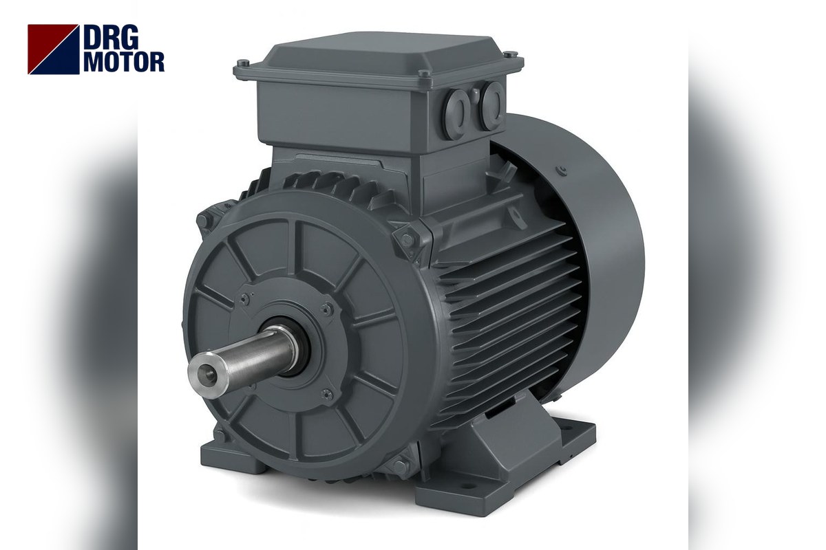

To run a three-phase motor forward and reverse, two contactors are used: K1 connects the motor to the supply in L1-L2-L3 order, while K2 connects it with two phases swapped (usually L1 and L3); when the phase sequence changes, the rotating field and the motor’s direction reverse. If both contactors close at the same time, two phases are short-circuited directly; that is why the circuit has both electrical and mechanical interlocking, and the motor is stopped with the STOP button before changing direction. For example, a 4 kW, 1500 rpm motor draws 7.95 A at 400 V; at every reversal the contactor makes and breaks 7.8 times that, about 62 A, so the contactor is chosen by utilisation category, not just by motor current.
Safety first: panel building, control wiring and commissioning must be done by a qualified electrician. Before changing any connection, switch off and lock out the fuses and confirm by measurement that there is no voltage. This article explains the circuit logic and how to choose the motor and contactors for machines that reverse often; you can find suitable motors by power and speed on the Buy Electric Motors Online page.
If you want to know why a motor runs backwards or how to make a one-off direction change at the terminals, see why an electric motor runs backwards and changing a motor’s direction of rotation; here we deal with repeated forward-reverse operation from a control circuit.
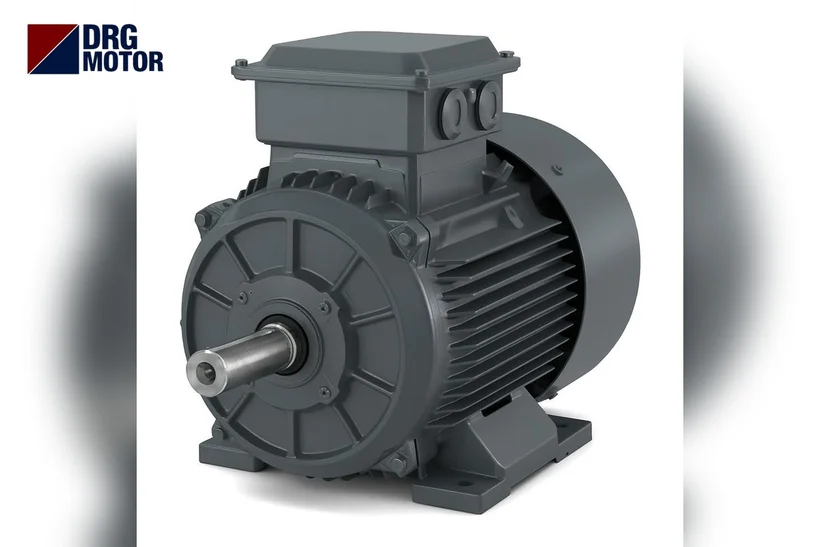
Power circuit: reversing the phases with two contactors
In the power circuit, the supply first passes through a motor protection breaker, or fuses and an overload relay, then splits in parallel to the two contactors. The contactor outputs join at the motor terminals. The only difference is the crossover at the K2 output:
| Supply phase | K1 (FORWARD) output → motor terminal | K2 (REVERSE) output → motor terminal |
|---|---|---|
| L1 | U1 | W1 |
| L2 | V1 | V1 |
| L3 | W1 | U1 |
L2 goes to V1 in both directions; L1 and L3 swap in K2. Rotating all three phases does not reverse the motor, it only shifts the sequence. The overload relay must sit in the common supply or common motor output of the contactors so that it monitors the same current in both directions. The star or delta link in the terminal box is independent of direction: 230/400 V motors such as the DRG-100L2-4 are star-connected on a 400 V supply, 400/690 V motors such as the DRG-112M-4 are delta-connected at 400 V.
Control circuit: FORWARD-STOP-REVERSE push-button logic
The control circuit is fed from a single fused phase (or a control transformer), and each coil branch contains the following elements in series.
| Branch | Series elements (in order) | Function |
|---|---|---|
| Common | Control fuse → overload relay normally closed (NC) contact → STOP button (NC) | De-energises both coils when the overload trips or STOP is pressed |
| Forward branch | FORWARD button (NO) ∥ K1 hold-in contact (NO) → NC contact of the REVERSE button → K2 auxiliary contact (NC) → K1 coil | Closes K1 and keeps it running without holding the button; blocks K1 while K2 is closed |
| Reverse branch | REVERSE button (NO) ∥ K2 hold-in contact (NO) → NC contact of the FORWARD button → K1 auxiliary contact (NC) → K2 coil | Closes K2; blocks K2 while K1 is closed |
The hold-in (self-latching) contact keeps the coil energised after the button is released. The cross-wired NC contacts of K1 and K2 in the control circuit form the “electrical interlock”: while one is closed, the other’s coil branch is open. The second interlock, made with the NC contacts of the buttons, is called “push-button interlocking”; pressing REVERSE first opens the forward branch.
Electrical and mechanical interlocking together
Electrical interlocking alone is not enough: a contactor with welded contacts may stay closed even when its coil is released, or close mechanically under vibration. A mechanical interlock is a part fitted between the two contactors that physically prevents one from closing while the other’s contacts are closed. Using both methods together means a single fault cannot turn into a phase-to-phase short circuit.
Reversing without passing through STOP: plugging
In a push-button-interlocked circuit, if REVERSE is pressed while the motor turns forward, K1 drops out, K2 closes immediately and the motor is connected to a reverse field while still turning forward. This is called plugging (counter-current braking). The motor is first braked to standstill, then accelerates in reverse; throughout this time the current stays at the starting-current level, and remains close to it until nearly at standstill.
- Contactor: both makes and breaks the starting current; the contacts wear quickly from arcing and may weld.
- Motor: the winding and rotor take a lot of heat in a short time; if repeated often the overload trips or the insulation ages.
- Mechanics: coupling, key, gearbox teeth, belt and the machine itself see a sudden torque shock.
That is why, in general practice, direction is changed only through STOP: instead of push-button interlocking, each direction button has “motor stopped” as a precondition. If inertia is high (heavy flywheel, long conveyor), the coil branch is held off by a timer relay or a zero-speed signal until the motor has fully stopped. If plugging is to be used deliberately, the motor and contactor must be selected for that duty and the machine maker’s approval obtained.
Loads that reverse often: doors, crane trolleys, mixers
If reversing is occasional (a conveyor whose direction is set a few times a day, a pump drain with a direction choice), the circuit and motor are no different from normal operation. The problem starts on machines where the direction changes very often or the motor starts and stops at short intervals:
- Sliding gates and doors: a start at every opening and closing, usually a small geared motor; end limit switches must be in series in both the K1 and K2 branches.
- Crane trolleys and bridge travel: the operator taps the button repeatedly (inching) while positioning; the contactor makes and breaks starting current at every tap.
- Mixers and washing drums: direction is reversed at set intervals; the program must include a pause between the two directions.
On such loads, motor heating depends on the number of starts. A motor with higher rated current and Is/In ratio produces more heat at every start; for frequent-start duty, choosing one size up in power and frame leaves thermal margin for the winding. If the number of starts is very high, reversing with a frequency inverter (ramped acceleration and deceleration) eliminates contactor wear and mechanical shock.
Contactor and overload selection: the AC-3 and AC-4 concept
Contactor current ratings are given per utilisation category. AC-3 means starting a squirrel-cage induction motor and switching it off while running: the contactor makes the starting current but breaks the rated current. AC-4 means breaking before the motor has accelerated, inching and plugging: the contactor both makes and breaks the starting current. The AC-4 rating of the same contactor is clearly lower than its AC-3 rating.
- For occasional reversing, the AC-3 current rating of both contactors must be above the motor’s rated current at the supply voltage.
- If there is inching or plugging, use the contactor maker’s AC-4 current rating; this must also be above the motor current.
- The contactor coil voltage must match the control voltage (e.g. 230 V AC or the control transformer output).
- The overload relay sits where it monitors both directions and is set to the motor’s nameplate current at the supply voltage. For the DRG-112M-4 that is 7.95 A at 400 V and 8.37 A at 380 V; for the DRG-100L2-4, 6.02 A at 400 V and 6.34 A at 380 V.
You can check contactor and overload sizes with the overload, fuse and contactor selection tool, and currents for other ratings with the motor current chart.
DRG motors for forward-reverse duty: current and contactor logic table
The current, Is/In and speed values in the table are DRG catalogue data; the starting current column is the 400 V rated current multiplied by Is/In. The last two columns show contactor selection as a comparison criterion without giving figures: the relevant category current of the chosen contactor in its catalogue must be above the motor current written here.
| Model | kW | Speed (rpm) | Frame | Current 400 V (A) | Current 380 V (A) | Is/In | Starting current 400 V (A, calculated) | Occasional reversing | Frequent reversing / plugging |
|---|---|---|---|---|---|---|---|---|---|
| DRG-802-4 | 0.75 | 1420 | 80 cast iron | 1.75 | 1.84 | 6.6 | 11.5 | AC-3 rating above 1.75 A | AC-4 rating above 1.75 A |
| DRG-90S-4 | 1.1 | 1445 | 90S cast iron | 2.48 | 2.61 | 6.8 | 16.9 | AC-3 rating above 2.48 A | AC-4 rating above 2.48 A |
| DRG-90L-4 | 1.5 | 1445 | 90L cast iron | 3.3 | 3.47 | 7 | 23.1 | AC-3 rating above 3.3 A | AC-4 rating above 3.3 A |
| DRG-100L1-4 | 2.2 | 1450 | 100L cast iron | 4.52 | 4.76 | 7.6 | 34.4 | AC-3 rating above 4.52 A | AC-4 rating above 4.52 A |
| DRG-100L2-4 | 3 | 1450 | 100L cast iron | 6.02 | 6.34 | 7.6 | 45.8 | AC-3 rating above 6.02 A | AC-4 rating above 6.02 A |
| DRG-112M-4 | 4 | 1450 | 112M cast iron | 7.95 | 8.37 | 7.8 | 62 | AC-3 rating above 7.95 A | AC-4 rating above 7.95 A |
| DRG-132S-4 | 5.5 | 1460 | 132S cast iron | 10.7 | 11.2 | 7.9 | 84.5 | AC-3 rating above 10.7 A | AC-4 rating above 10.7 A |
| DRG-132M-4 | 7.5 | 1460 | 132M cast iron | 14.3 | 15 | 7.5 | 107.2 | AC-3 rating above 14.3 A | AC-4 rating above 14.3 A |
| DRG-160M-4 | 11 | 1465 | 160M cast iron | 20.4 | 21.5 | 7.7 | 157.1 | AC-3 rating above 20.4 A | AC-4 rating above 20.4 A |
Four-pole motors of the 1500 rpm class are the most common choice for geared door, travel and mixer drives; aluminium-frame versions of the same models are also in the store.
Commissioning checklist
- In the power circuit, check the crossover at the K2 output (L1↔L3) and that L2 goes to the same terminal in both directions.
- Before energising with the motor connected, try to close K1 and K2 at the same time by hand (test button); the mechanical interlock must not allow it.
- Verify with a meter that each coil branch of the control circuit contains the NC contact of the opposite contactor.
- Make the first run with the motor uncoupled from the machine; compare the FORWARD direction with the direction the machine expects, and if it is wrong, swap two phases in the motor cable, not at the K1 and K2 inputs.
- Set the overload relay to the nameplate current; use its test button to confirm that its contact breaks both branches.
- On door and travel drives, test with the motor running that the end limit switches cut the branch for the relevant direction.
- Press REVERSE while the motor is running: if the circuit is built to reverse only through STOP, the motor must not switch to the opposite direction.
Motors in this power range
Four-pole models commonly used on machines with forward-reverse control:
- DRG-90L-4 – 1.5 kW – 1445 rpm – 90L cast iron
- DRG-100L2-4 – 3 kW – 1450 rpm – 100L cast iron
- DRG-112M-4 – 4 kW – 1450 rpm – 112M cast iron
- DRG-132S-4 – 5.5 kW – 1460 rpm – 132S cast iron
- DRG-132M-4 – 7.5 kW – 1460 rpm – 132M cast iron
Click to see current prices and order these motors nowSEE PRICES →
Frequently Asked Questions
How do you reverse a three-phase motor?
Swap any two of the three phases feeding the motor. For a permanent change this is done in the motor cable; if frequent reversing is needed, a two-contactor forward-reverse circuit is built and K2 connects with two phases crossed.
Why is interlocking needed in a reversing circuit?
If both contactors close at the same time, two phases are connected directly and a short circuit occurs. Electrical interlocking (the NC contact of the opposite contactor) and a mechanical interlock are used together so that a single fault cannot become a short circuit.
What happens if a motor is reversed while it is still turning?
Plugging occurs: the motor draws current at starting-current level until it stops, the contactor contacts wear, and the coupling and gearbox take a shock. On the 4 kW DRG-112M-4 this current is about 62 A at 400 V. That is why direction should be changed through STOP and only after the motor has stopped.
Where does the overload go in a reversing circuit, and what is the setting?
The overload relay sits in the common supply or common motor output of the two contactors so that it protects both directions; its NC contact is wired in series in the common branch of the control circuit. The setting is the motor’s nameplate current at the supply voltage; 7.95 A at 400 V for the DRG-112M-4.
Contact us to choose the right motor and frame for your machine: phone +90 (542) 666 11 11, e-mail [email protected], contact page https://drgmotor.com/en/contact. DRG Motor is an electric motor manufacturer and supplier; you can order straight away from the 120 models in our online store.