English
 Le français
 Türkçe

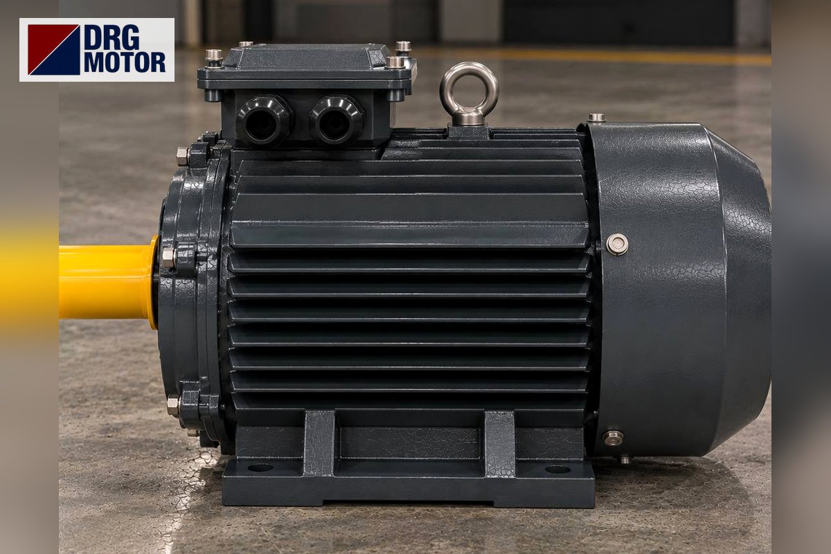

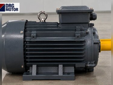
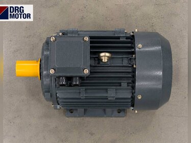
DRG Motor's eight cast iron models in the 1500 rpm class from 75 kW to 315 kW fall into three flange families: frames 280S/280M with a B5 flange of P 550 mm, frames 315S/315M/315L with P 660 mm and frames 355M/355L with P 800 mm outer diameter. At these ratings the 4-pole shaft is 75×140, 85×170 and 100×170 mm, so the shaft changes together with the flange family.
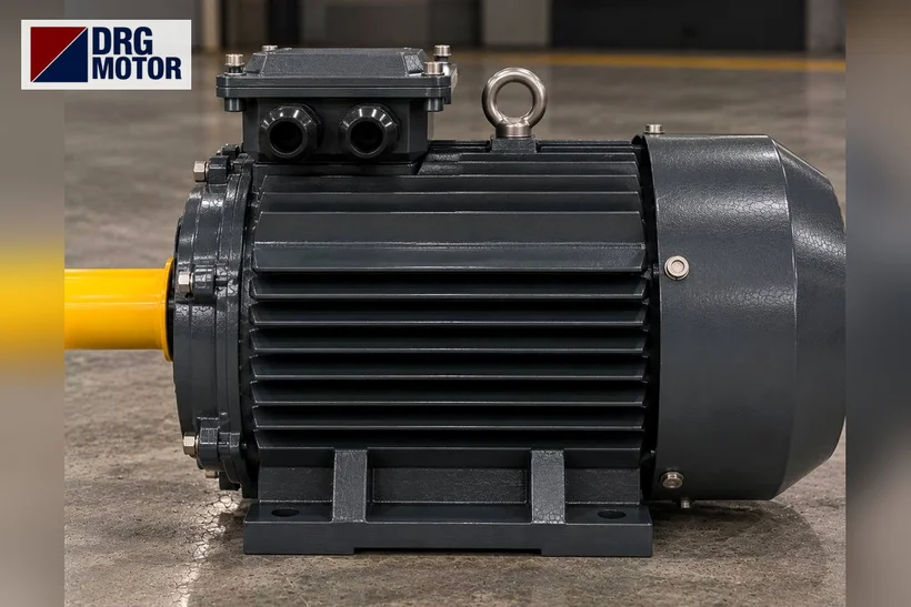
All models belong to the three-phase asynchronous electric motors range and their product pages are listed in the online motor shop. Readers looking for a B5 flange motor of this size are usually maintenance or project teams mounting a motor on a large gearbox, vertical pump, agitator or fan housing; a mistake here means lifting the motor off site and sending it back. That is why this article focuses on the mating surface rather than on power.
Power → frame → shaft: 1500 rpm from 75 kW to 315 kW
The table below comes from DRG product records. "1500 rpm" is the speed class (4-pole, synchronous speed); the value in the third column is the rated speed on the nameplate. All models have 400/690 V (Δ/Y) connection.
| Model | Power | IEC frame / rated speed | Shaft D×E, key F (mm) |
|---|---|---|---|
| DRG-280S-4 | 75 kW / 100 HP | 280S / 1486 rpm | 75×140, F 20 |
| DRG-280M-4 | 90 kW / 125 HP | 280M / 1486 rpm | 75×140, F 20 |
| DRG-315S-4 | 110 kW / 150 HP | 315S / 1488 rpm | 85×170, F 22 |
| DRG-315M-4 | 132 kW / 180 HP | 315M / 1488 rpm | 85×170, F 22 |
| DRG-315L1-4 | 160 kW / 200 HP | 315L / 1488 rpm | 85×170, F 22 |
| DRG-315L2-4 | 200 kW / 270 HP | 315L / 1490 rpm | 85×170, F 22 |
| DRG-355M-4 | 250 kW / 340 HP | 355M / 1490 rpm | 100×170, F 25 |
| DRG-355L-4 | 315 kW / 430 HP | 355L / 1490 rpm | 100×170, F 25 |
Two practical points follow. First, the frame jumps twice as power increases: from 90 kW to 110 kW you move from 280 to 315, and from 200 kW to 250 kW from 315 to 355; at each jump the flange, the shaft and the shaft end thread change together. Second, within one frame family the flange and shaft stay the same while power grows; the DRG-315S-4 and the DRG-315L2-4, for example, carry the same 660 mm flange and 85×170 mm shaft.
Selection traps: two ratings in 315L, 2-pole rows, shaft end thread
- 315L1 and 315L2: both use the IEC 315L frame; in DRG records their B3 dimensions (including L 1334 mm and B 508 mm) are the same, while power is 160 kW and 200 kW. Writing only "315L" on an order is not enough; always state L1/L2 from the model code or the power.
- The 2-pole row in the catalogue: the B5 table has two rows per frame. The flange (P, N, M, S) is identical in both, but the shaft is not: the 2-pole row shows a 65×140 mm shaft on frames 280 and 315 and 75×140 mm on 355. For a 1500 rpm motor the correct row is "4-pole and above"; preparing a coupling or input hub from the wrong row is one of the costliest errors.
- Shaft end thread: M20×42 on frames 280 and 315, M24×50 on 355. If a mounting tool or hub puller relies on the shaft end thread, this changes too when moving to 355.
For shaft diameters across all ratings see the motor shaft diameter by kW table, and for ordering by shaft and frame size the motor frame size order guide.
Click to see current electric motor prices and order nowSEE PRICES →
B5 flange P/N/M/S table: frames 280, 315 and 355
Values are taken from the IM B5 large-flange rows of the DRG catalogue and are identical for every S/M/L length within the same frame family. The last two rows are our own calculation: (M − N) / 2 is the radial distance from hole centre to spigot diameter, (P − M) / 2 from hole centre to the flange outer edge.
| B5 dimension (mm) | 280S, 280M | 315S, 315M, 315L | 355M, 355L |
|---|---|---|---|
| P – flange outer diameter | 550 | 660 | 800 |
| N – spigot (pilot) diameter | 450 | 550 | 680 |
| M – bolt circle diameter | 500 | 600 | 740 |
| S – flange hole diameter | 18.5 | 24 | 24 |
| T – spigot depth | 5 | 6 | 6 |
| LA – flange thickness | 22 | 22 | 25 |
| D×E – shaft (4-pole and up) | 75×140 | 85×170 | 100×170 |
| F – key width | 20 | 22 | 25 |
| G – shaft to key-seat bottom | 67.5 | 71 | 86 |
| DH – shaft end thread | M20×42 | M20×42 | M24×50 |
| (M − N) / 2 | 25 | 25 | 30 |
| (P − M) / 2 | 25 | 30 | 30 |
Flange values for all frames from 63 to 355 are in the B5 motor flange dimensions table; only the three flanges of this power band are shown here. The general advantages of a large flange are covered in large flange electric motor, and the difference between the FF (through-hole) and FT (tapped) flange in B5 and B14 flange FF/FT difference. The B14 small-flange table is not part of the DRG catalogue, so we give no B14 or B34 dimensions for these frames.
Spigot and bolt-hole checks on P 550–800 mm flanges
On a large flange it is the N spigot, not the bolts, that locates the motor on the axis. The bolts only clamp; because the holes are larger than the bolts, alignment is set by the spigot. On the mating part (gearbox input flange, pump lantern, machine face) check the spigot recess diameter and depth first, then the holes:
| Check | How to do it | DRG data (280 / 315 / 355) |
|---|---|---|
| Flange outer diameter P | Outer diameter of the mating flange or the space available | 550 / 660 / 800 mm |
| Spigot N | Inner diameter of the mating recess (caliper, several points) | 450 / 550 / 680 mm |
| Spigot depth T | Recess depth must not be less than T | 5 / 6 / 6 mm |
| Bolt circle M | Centre-to-centre of two opposite holes (even hole count) | 500 / 600 / 740 mm |
| Hole diameter S | Hole or thread size on the mating flange; choose bolts accordingly | 18.5 / 24 / 24 mm |
| Number of holes | Count the holes on the mating flange | Not in the catalogue table → confirm |
| Shaft and thread | Shaft diameter/length, key, shaft end thread | 75×140 / 85×170 / 100×170; M20×42 / M20×42 / M24×50 |
The number of holes is not given in the DRG catalogue table; even when bolt circle and hole size match, the hole count and angular pattern on the mating flange must be confirmed separately. Frames 315 and 355 share the same hole diameter S (24 mm) but differ in P, N and M, so the frame family cannot be guessed from bolt size alone. The safest way to check is to overlay the files from the 2D technical drawings and 3D technical drawings pages on the mating-part drawing.
Current and torque: the load the flange transmits
The flange also transfers the reaction of the motor torque to the mating part. Torque values come from DRG records; the last column is our check with M = 9550·P/n (P in kW, n = nameplate speed in rpm); small differences are due to rounding.
| Model | Current at 400 V (A) | Rated torque (Nm) | Check: 9550·P/n |
|---|---|---|---|
| DRG-280S-4 | 129 | 482 | 9550·75/1486 = 482 |
| DRG-280M-4 | 155 | 578.4 | 9550·90/1486 = 578.4 |
| DRG-315S-4 | 187 | 706 | 9550·110/1488 = 706 |
| DRG-315M-4 | 224 | 847.2 | 9550·132/1488 = 847.2 |
| DRG-315L1-4 | 271 | 1027 | 9550·160/1488 = 1026.9 |
| DRG-315L2-4 | 334 | 1282 | 9550·200/1490 = 1281.9 |
| DRG-355M-4 | 418 | 1602 | 9550·250/1490 = 1602.3 |
| DRG-355L-4 | 526 | 2019 | 9550·315/1490 = 2019 |
From 75 kW to 315 kW rated torque rises from 482 Nm to 2019 Nm, about 4.2 times, while the flange outer diameter grows from 550 mm to 800 mm. For cable and protection sizing use the 400 V current with the motor current chart and the motor cable size calculator; every model has a 2 × M63×1,5 cable entry.
Vertical mounting (V1): confirm before ordering
B5 flange motors are often mounted shaft-down (V1) on top of pumps or agitators. In this power band vertical use must be stated clearly on the order and confirmed, because in a vertical position the rotor weight and the axial load from the machine act on the bearings differently than in horizontal mounting. DRG records list 6317-C3 bearings on frame 280, 6319-C3 on 315 and 6322-C3 on 355; this alone does not tell you the permissible axial load in vertical service. Send us the axial force the pump or agitator puts on the shaft, the mounting position (V1 shaft down / V3 shaft up) and the environment (outdoor, washdown, dust) and we will confirm suitability model by model. Mounting codes are explained in motor mounting types B3, B5, B14 and B35.
Limits of flange-only support and the B35 option
In horizontal B5 mounting the whole motor weight, spread along the housing, hangs from the flange on the mating part. Overall length in these frames ranges from 982 mm to 1516 mm:
| Model | L – overall length (mm) | AC – housing diameter (mm) | Bearing record |
|---|---|---|---|
| DRG-280S-4 | 982 | 547 | 6317-C3 |
| DRG-280M-4 | 1033 | 547 | 6317-C3 |
| DRG-315S-4 | 1224 | 620 | 6319-C3 |
| DRG-315M-4 | 1334 | 620 | 6319-C3 |
| DRG-315L1-4 | 1334 | 620 | 6319-C3 |
| DRG-315L2-4 | 1334 | 620 | 6319-C3 |
| DRG-355M-4 | 1516 | 698 | 6322-C3 |
| DRG-355L-4 | 1516 | 698 | 6322-C3 |
The general principle: the longer the motor, the further its centre of gravity sits from the flange face, putting a bending load on the flange, the bolts and the mating housing; vibration increases that load. If the mating part is not designed for it, instead of carrying the motor on the flange alone consider a foot-plus-flange (B35) connection or a separate support at the rear. We do not quote motor weight or permissible flange load in this article; the load limit given by the mating-part maker and the motor model must be assessed together. State a B35 requirement on the order and we will confirm it for the frame; how to write B3, B5 and B35 orders is covered in the B3, B5 and B35 mounting order guide.
Frequently asked questions
What are the flange dimensions of a 90 kW 1500 rpm B5 motor?
The DRG-280M-4 uses frame 280M: P 550, N 450, M 500, S 18.5 mm; shaft 75×140 mm, key 20 mm. The 75 kW DRG-280S-4 has the same flange and shaft but a different overall length (982 / 1033 mm).
Does the flange change between 200 kW and 250 kW?
Yes. The 200 kW 315L has a P 660 mm flange and 85×170 mm shaft; the 250 kW 355M has a P 800 mm flange and 100×170 mm shaft. Mating part and coupling change together.
Do two flanges with the same hole diameter belong to the same frame?
No. Frames 315 and 355 share S 24 mm, but the bolt circle (600 / 740 mm) and spigot (550 / 680 mm) differ.
Can I ask for a 160 kW motor with a B14 small flange?
The B14 dimension table is not in the DRG catalogue. If you need B14 or B34, send the flange outer diameter, bolt circle, spigot diameter and thread size on WhatsApp and we will check it.
Technical confirmation and ordering
DRG Motor is an electric motor manufacturer, supplier and seller. At this size the fastest route is to send a photo of the existing nameplate, the P, N, M, S dimensions and hole count of the mating flange, the shaft diameter and the mounting position (horizontal/V1). For general features of large cast iron frames see cast iron frame and high kW motors and the DRG technical and product catalogue.
Send a photo of your current motor nameplate and we will find the suitable DRG model together.Send on WhatsApp
Browse the 1500 rpm motors in frames 280–355 and their current pricesSEE PRICES
Electric Motors Related to This Topic — Models and Current Prices
Suitability is not decided by power alone: compare the speed, voltage, mounting, shaft and fixing dimensions of your machine with the product data; if unsure, send us the nameplate of your current motor.
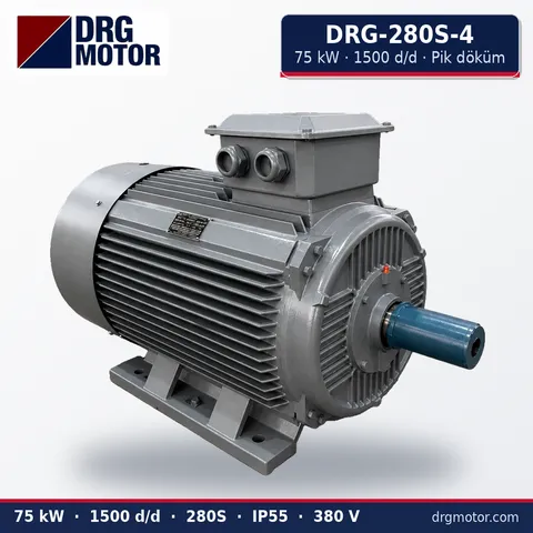
75 kW Three-Phase Motor 1500 rpm – DRG-280S-4 Cast Iron
- 75 kW · 1500 rpm (4 poles)
- Cast iron frame · IEC 280S
- Shaft: 75 × 140 mm
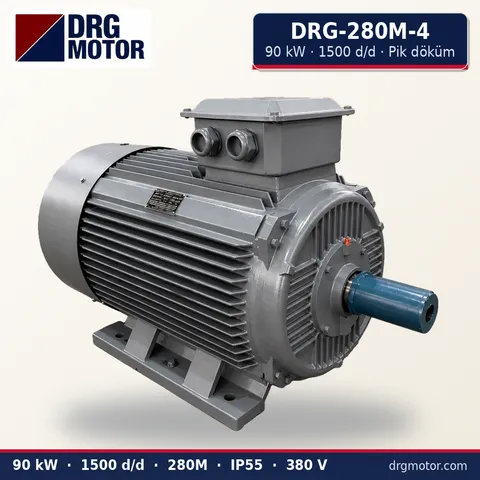
90 kW Three-Phase Motor 1500 rpm – DRG-280M-4 Cast Iron
- 90 kW · 1500 rpm (4 poles)
- Cast iron frame · IEC 280M
- Shaft: 75 × 140 mm
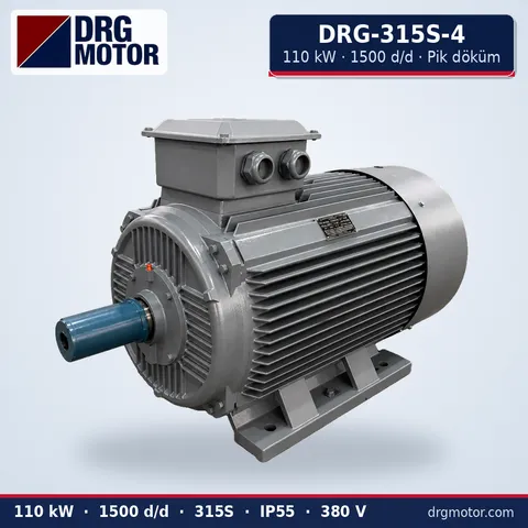
110 kW Three-Phase Motor 1500 rpm – DRG-315S-4 Cast Iron
- 110 kW · 1500 rpm (4 poles)
- Cast iron frame · IEC 315S
- Shaft: 85 × 170 mm
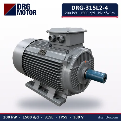
200 kW Three-Phase Motor 1500 rpm – DRG-315L2-4 Cast Iron
- 200 kW · 1500 rpm (4 poles)
- Cast iron frame · IEC 315L
- Shaft: 85 × 170 mm
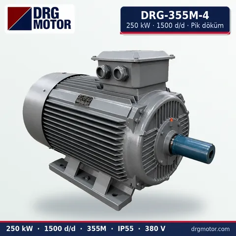
250 kW Three-Phase Motor 1500 rpm – DRG-355M-4 Cast Iron
- 250 kW · 1500 rpm (4 poles)
- Cast iron frame · IEC 355M
- Shaft: 100 × 170 mm
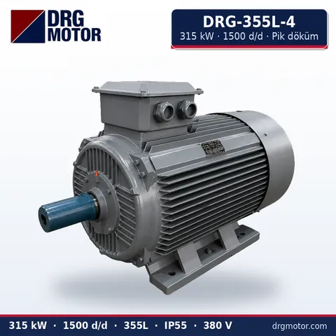
315 kW Three-Phase Motor 1500 rpm – DRG-355L-4 Cast Iron
- 315 kW · 1500 rpm (4 poles)
- Cast iron frame · IEC 355L
- Shaft: 100 × 170 mm