 English
 Türkçe


DRG Motor 2D technical drawings are dimensioned outline drawings prepared for engineers, machine designers and assembly teams who integrate our motors into their projects. These drawings contain all the external dimensions you need to mount the motor to a machine, chassis or foundation. By downloading the PDF file on this page, you can access the fully dimensioned 2D drawing of the relevant motor.
What Is a 2D Technical Drawing?
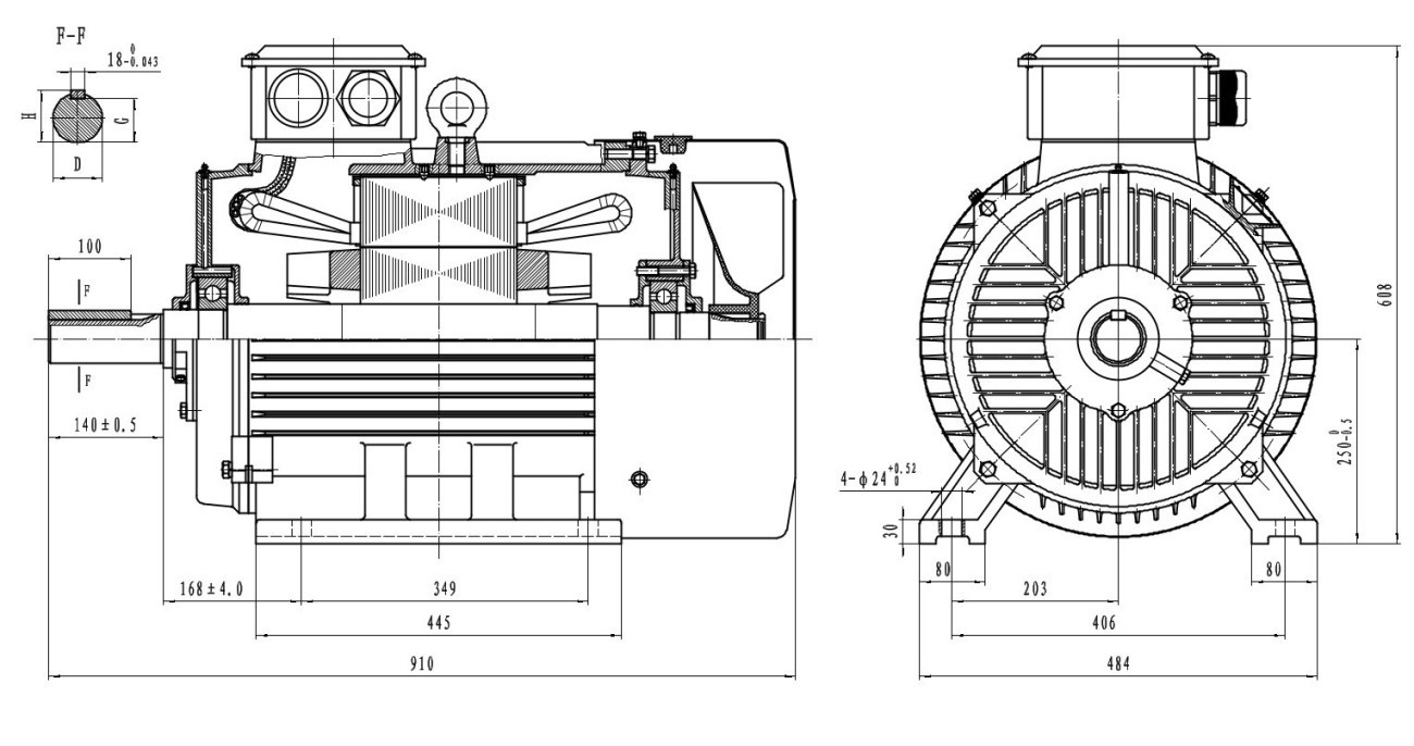
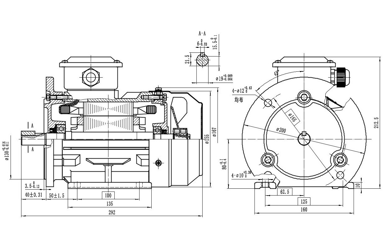
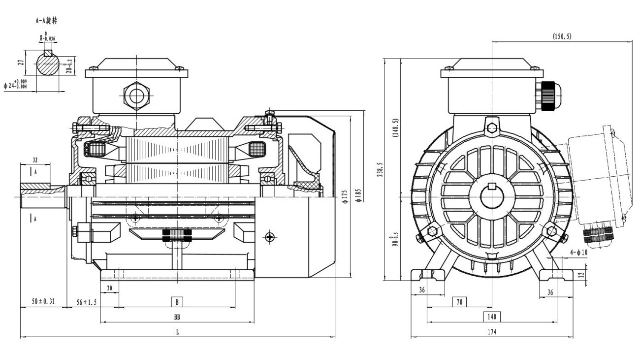
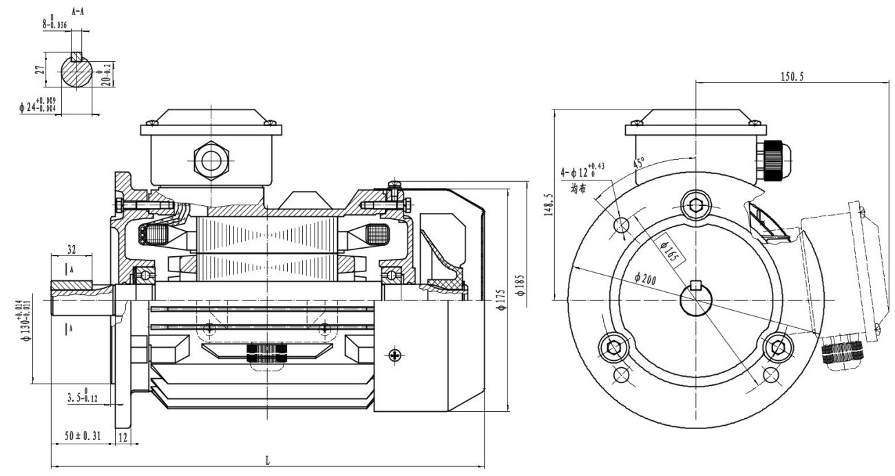
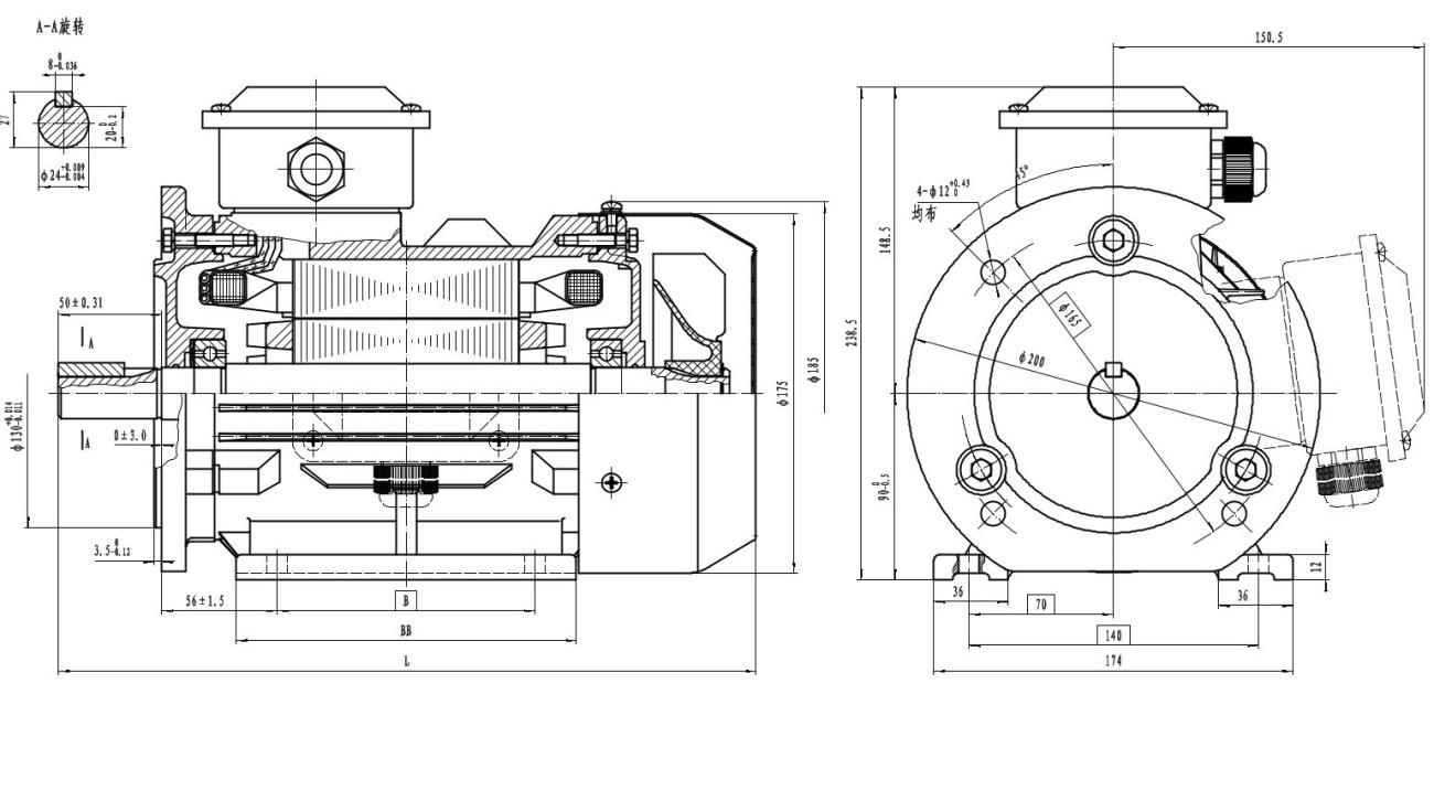
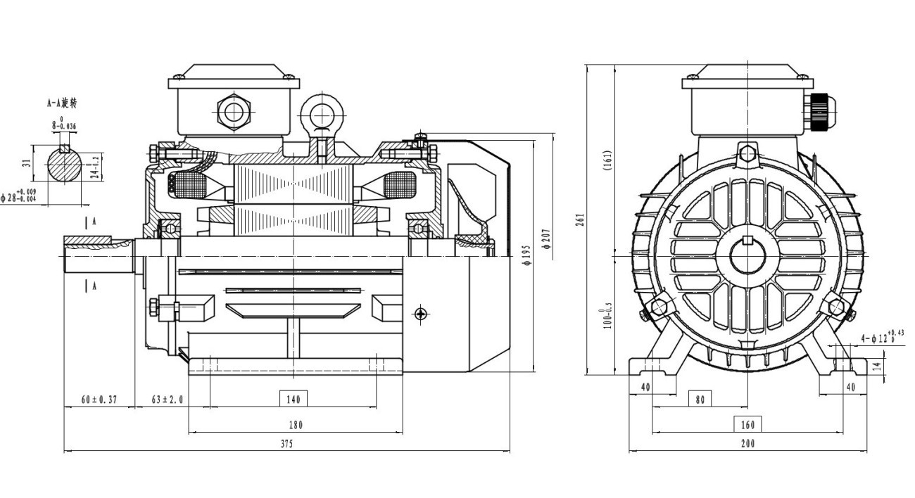
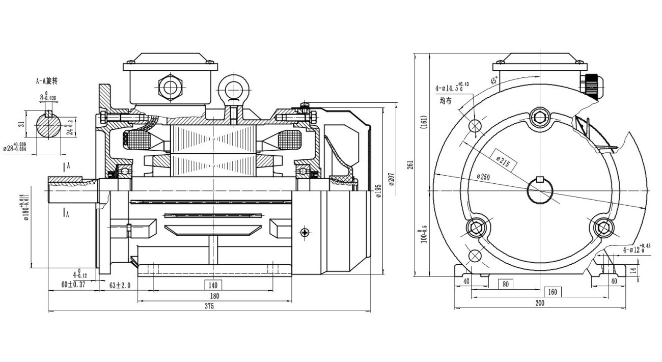
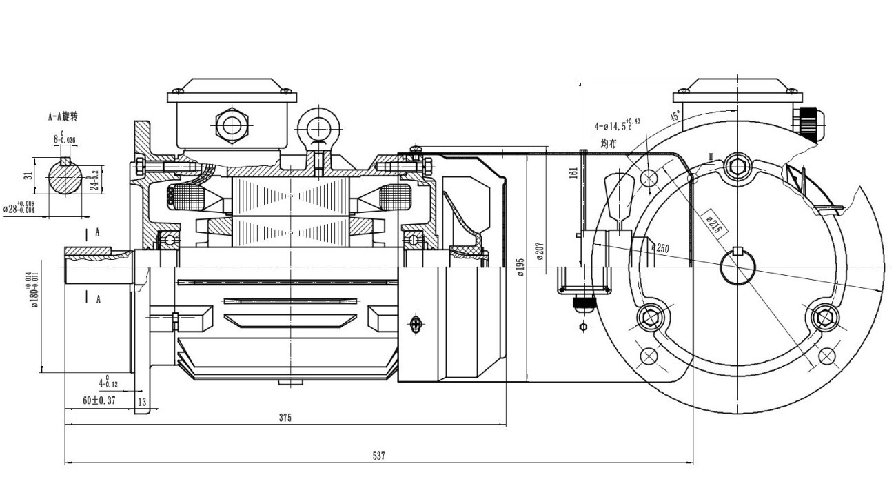
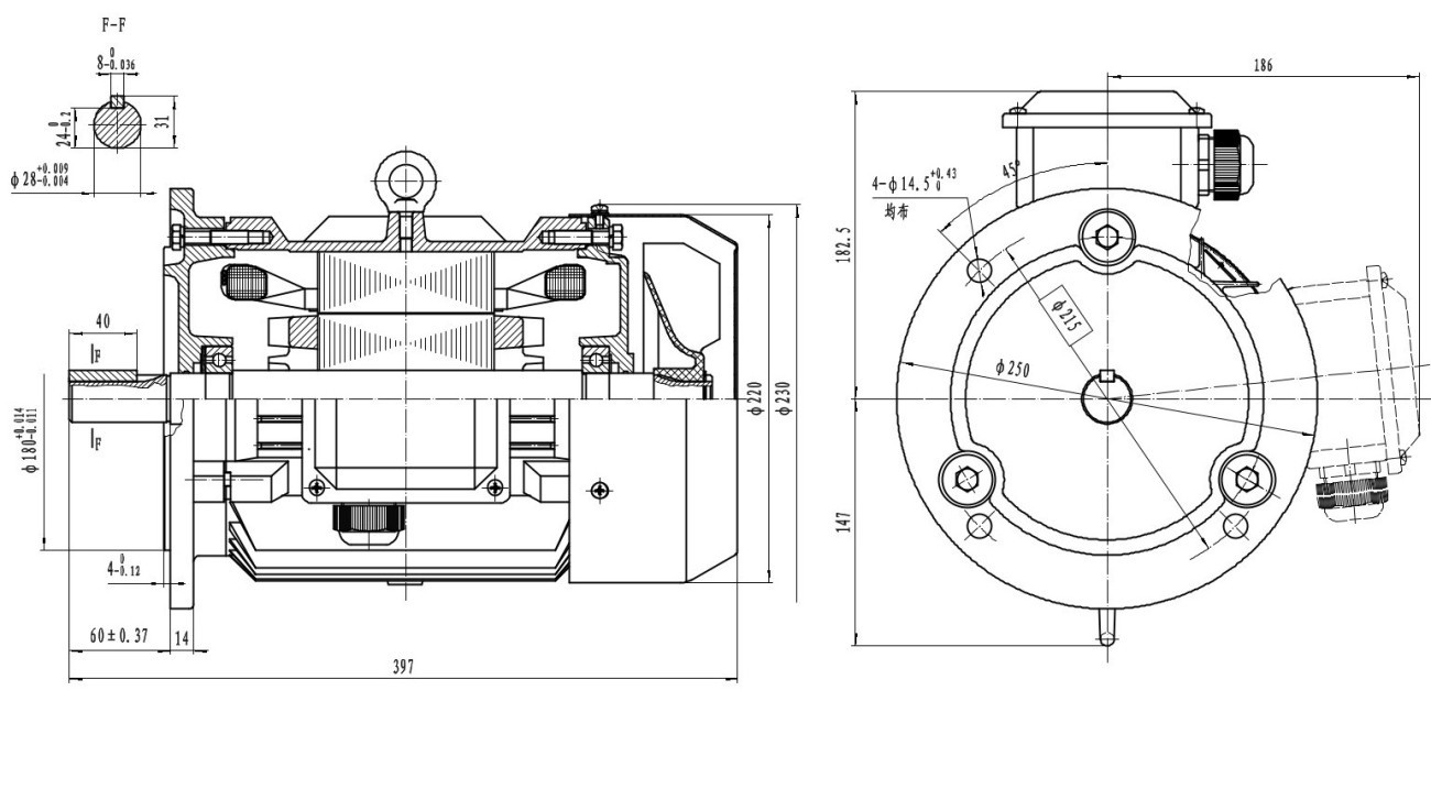
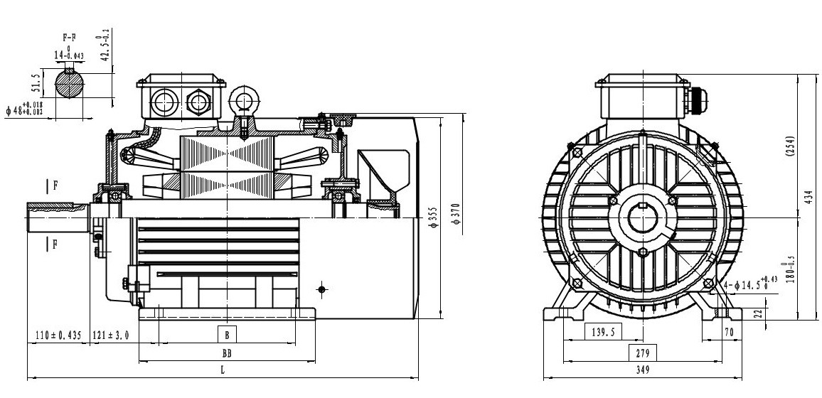
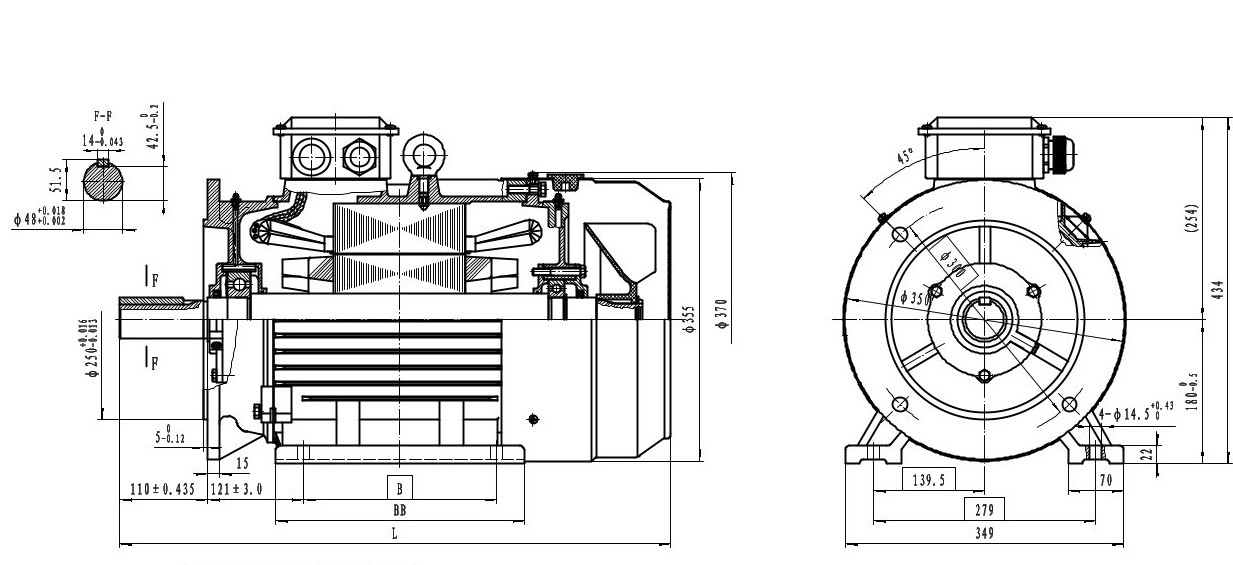
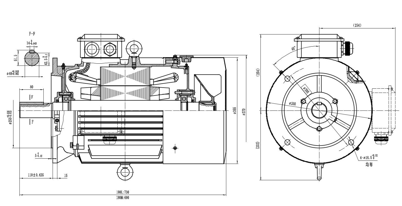
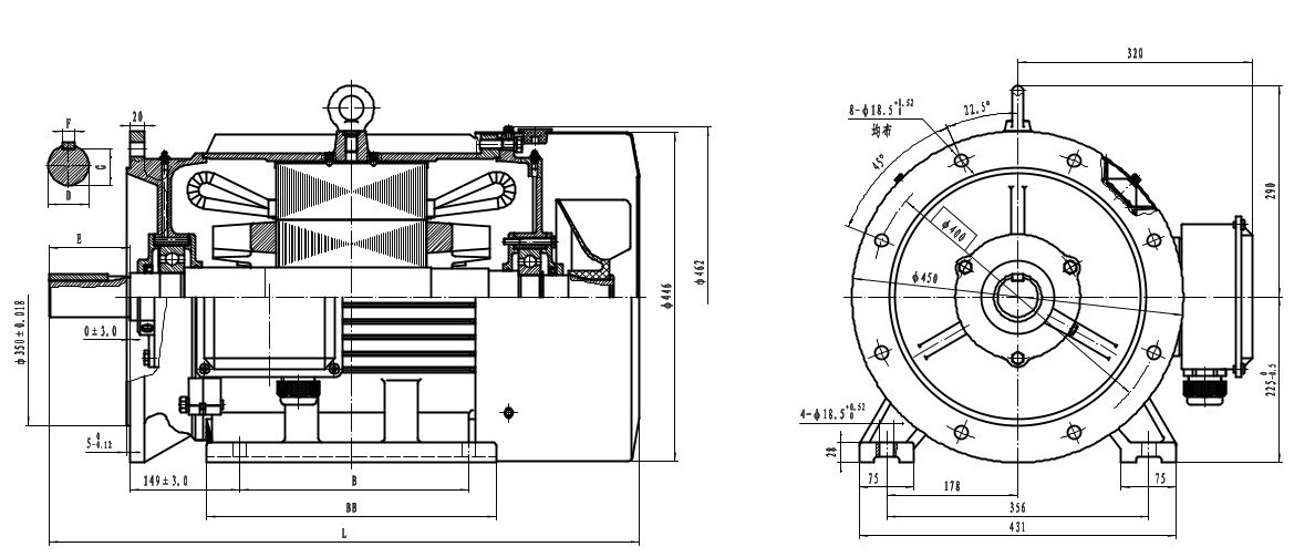
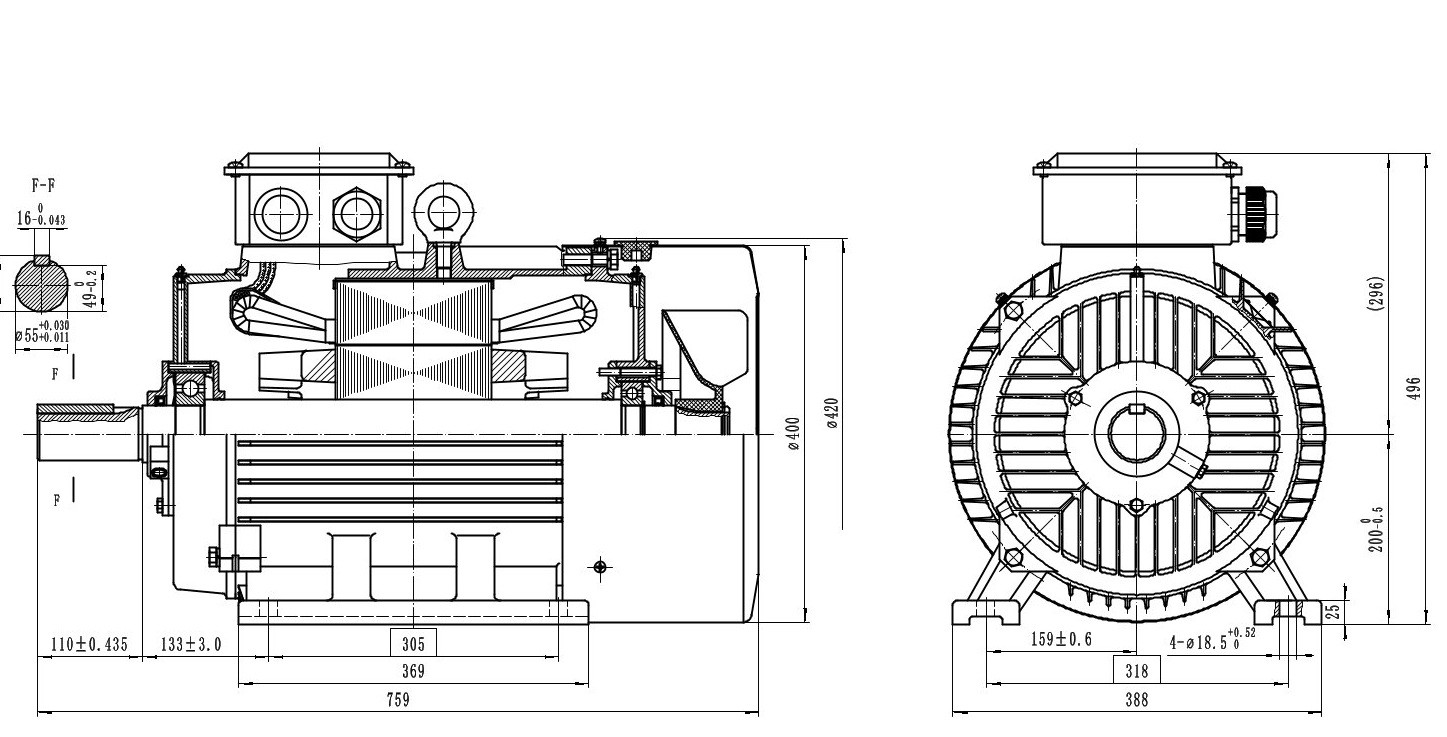
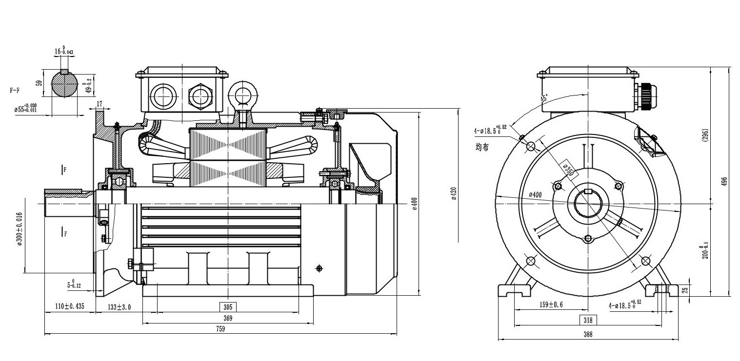
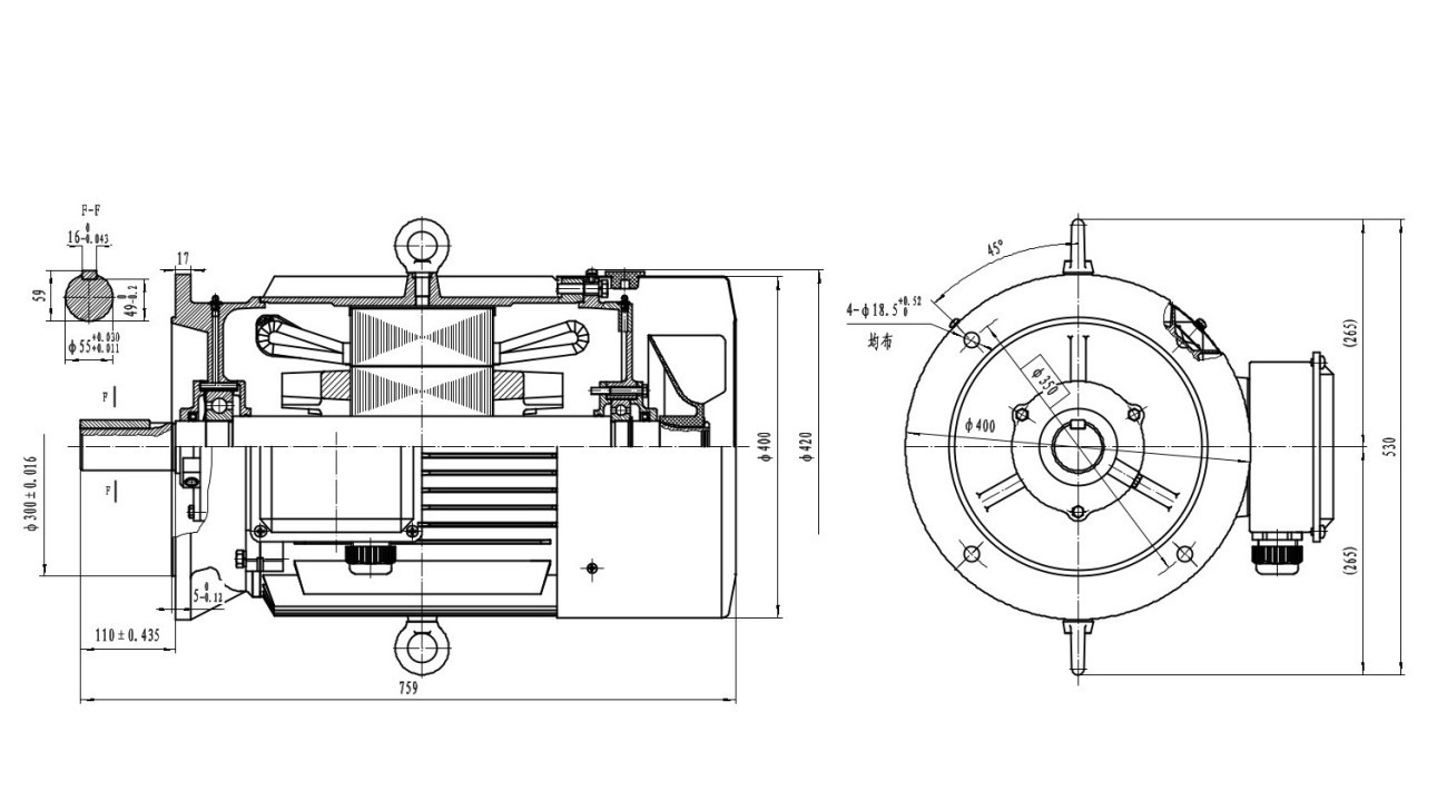
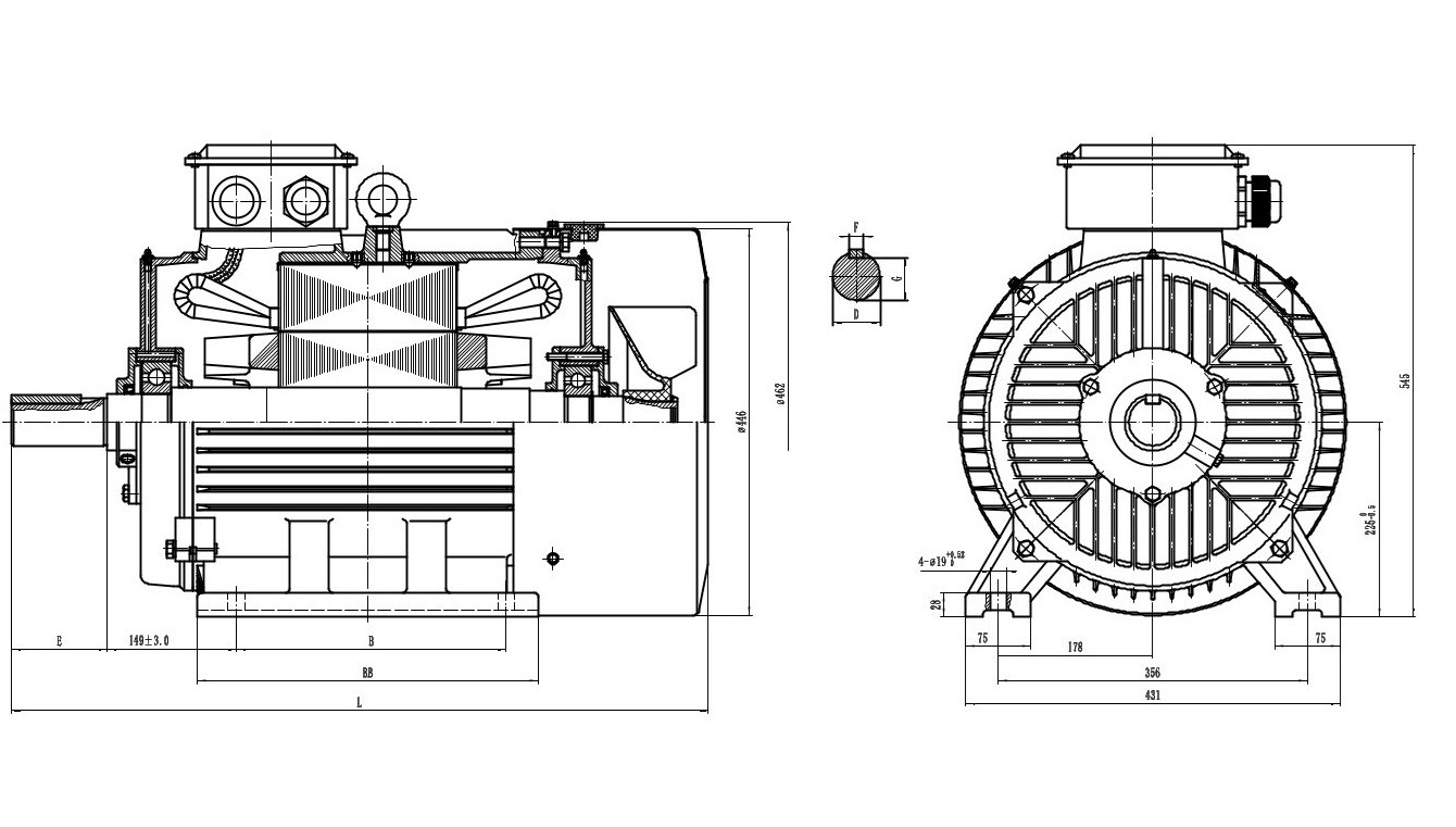
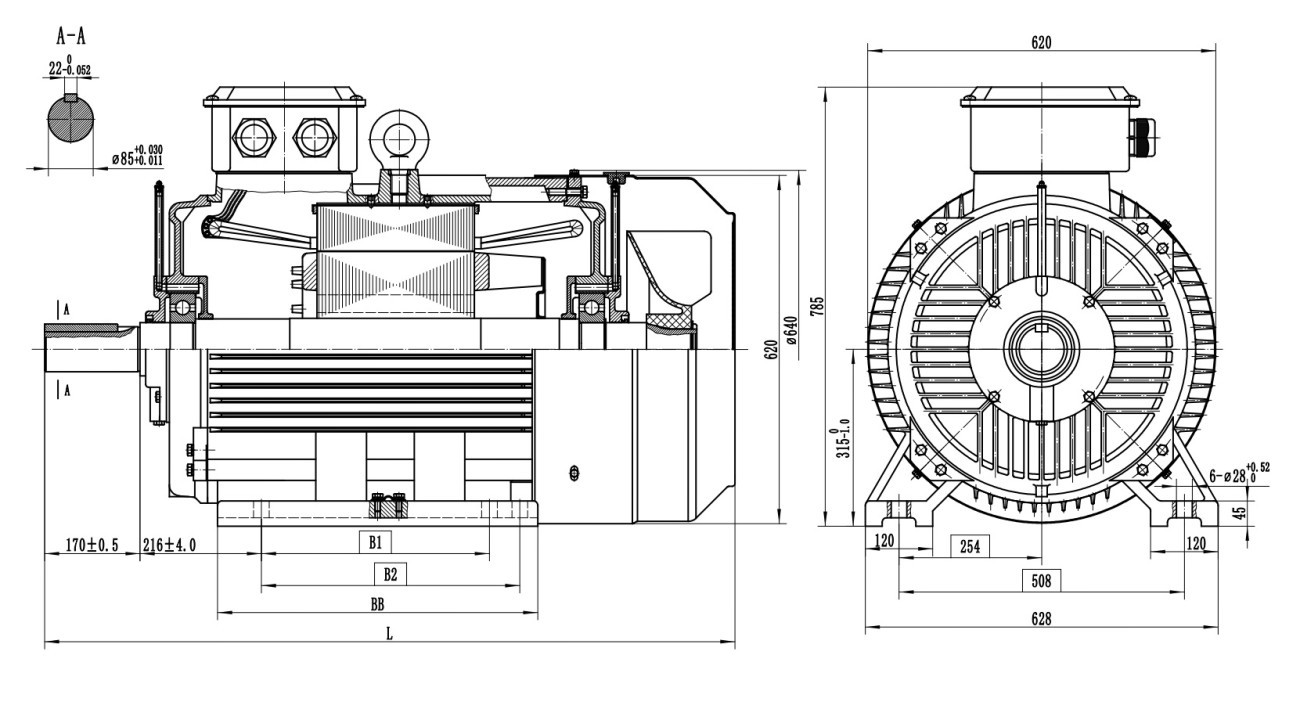
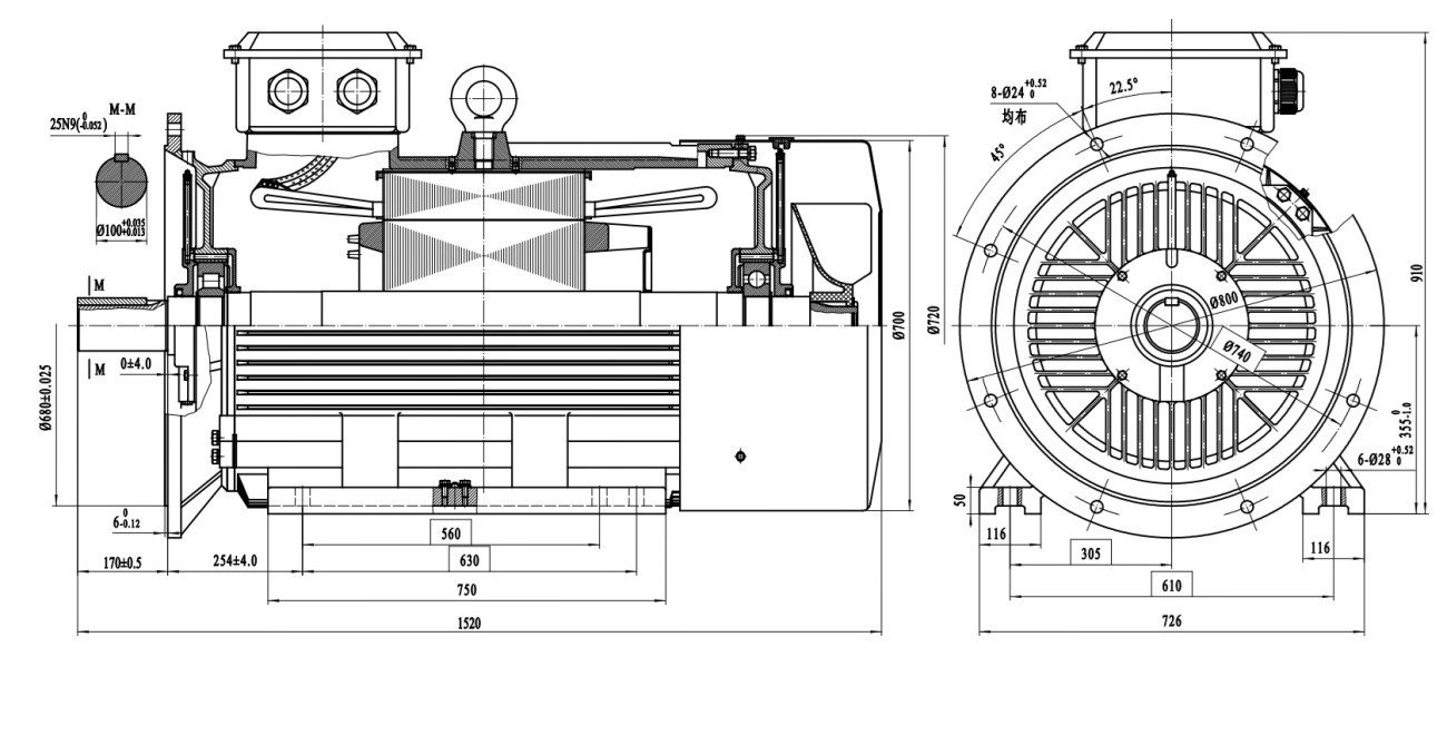
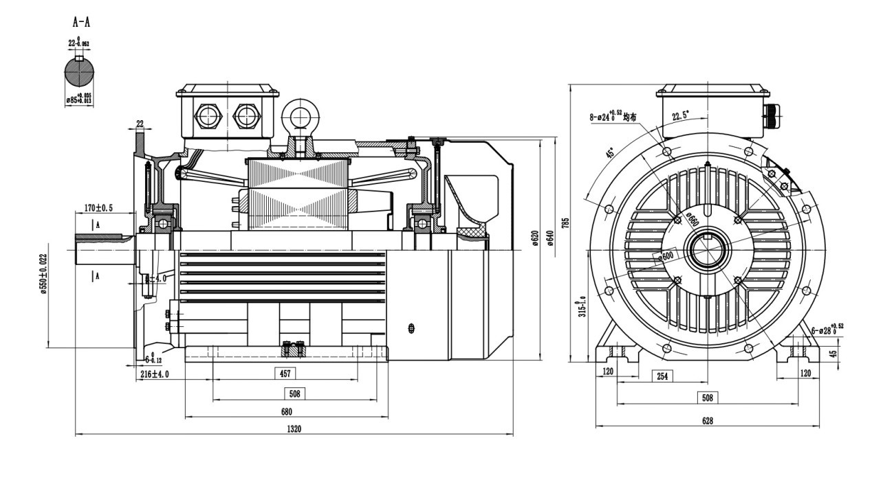
A 2D technical drawing is the two-dimensional, dimensioned representation of a motor through side views, front/flange views and section details. Designers use these drawings to plan connection points, align couplings and pulleys, and create the hole layout for the foundation and chassis. Before purchasing the motor, you can verify on these drawings whether it fits your machine exactly.
Which Dimensions Are Shown?
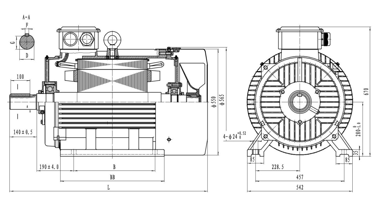
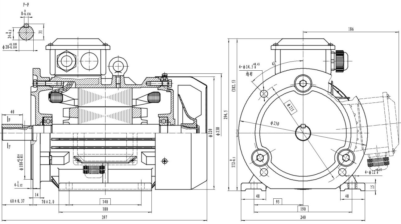
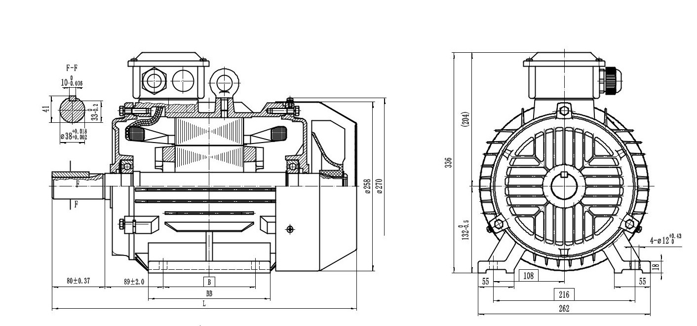
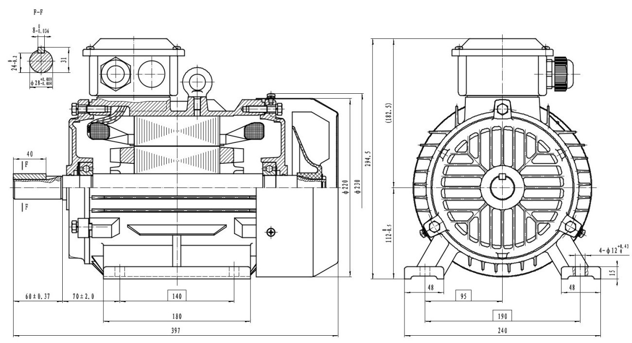
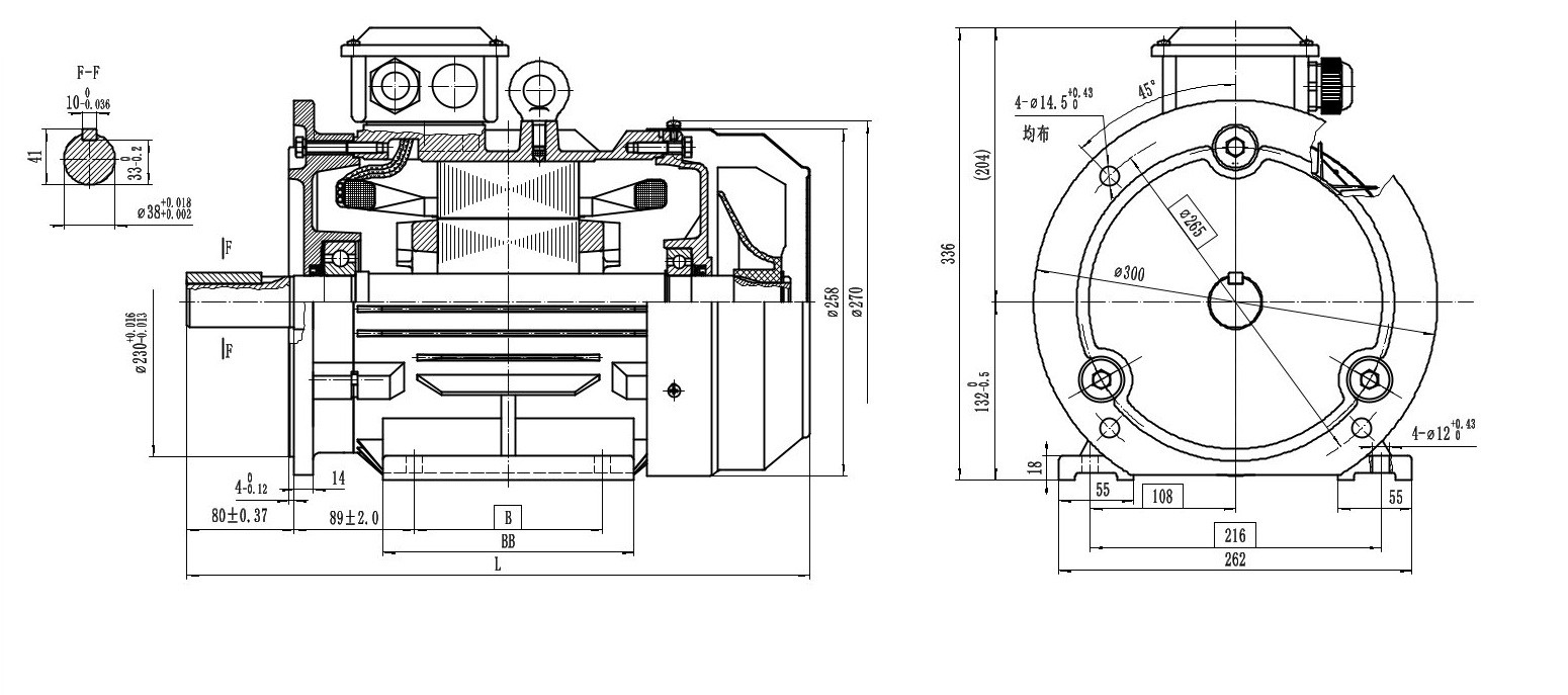
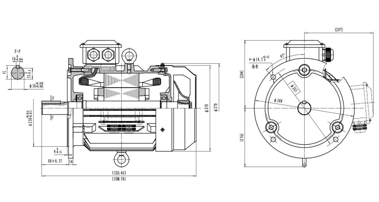
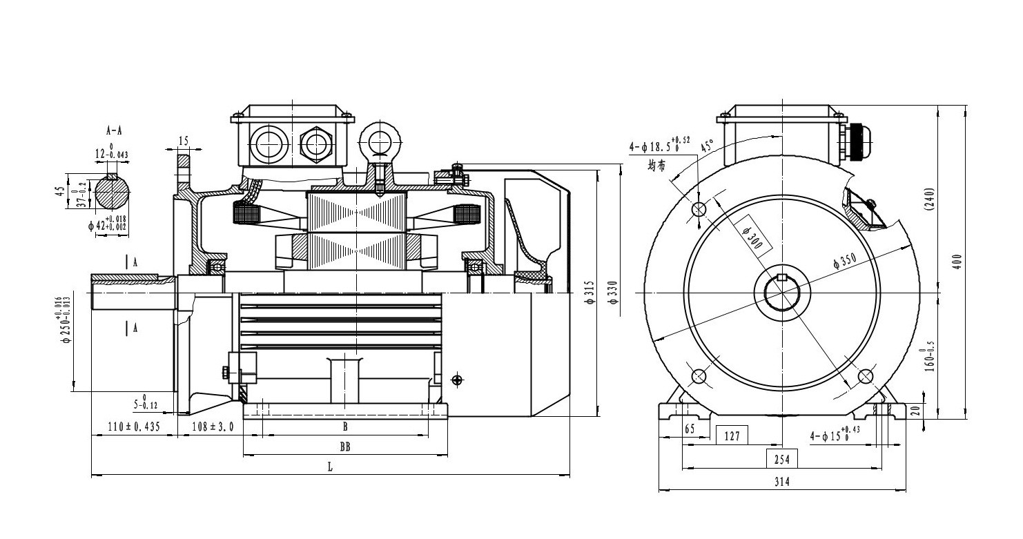
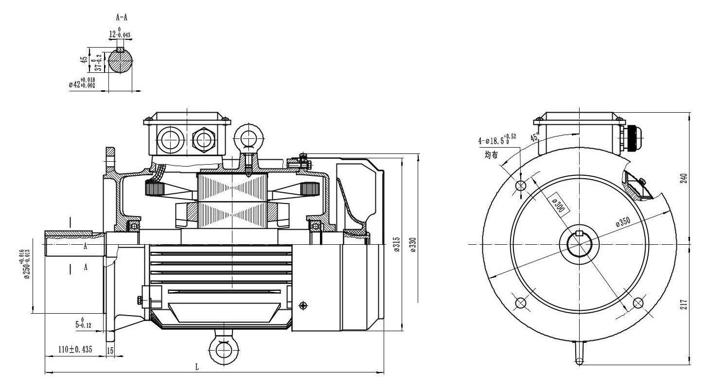
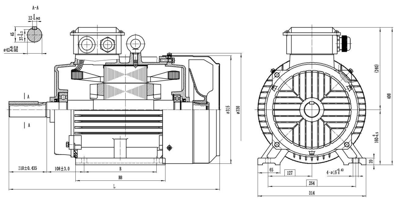
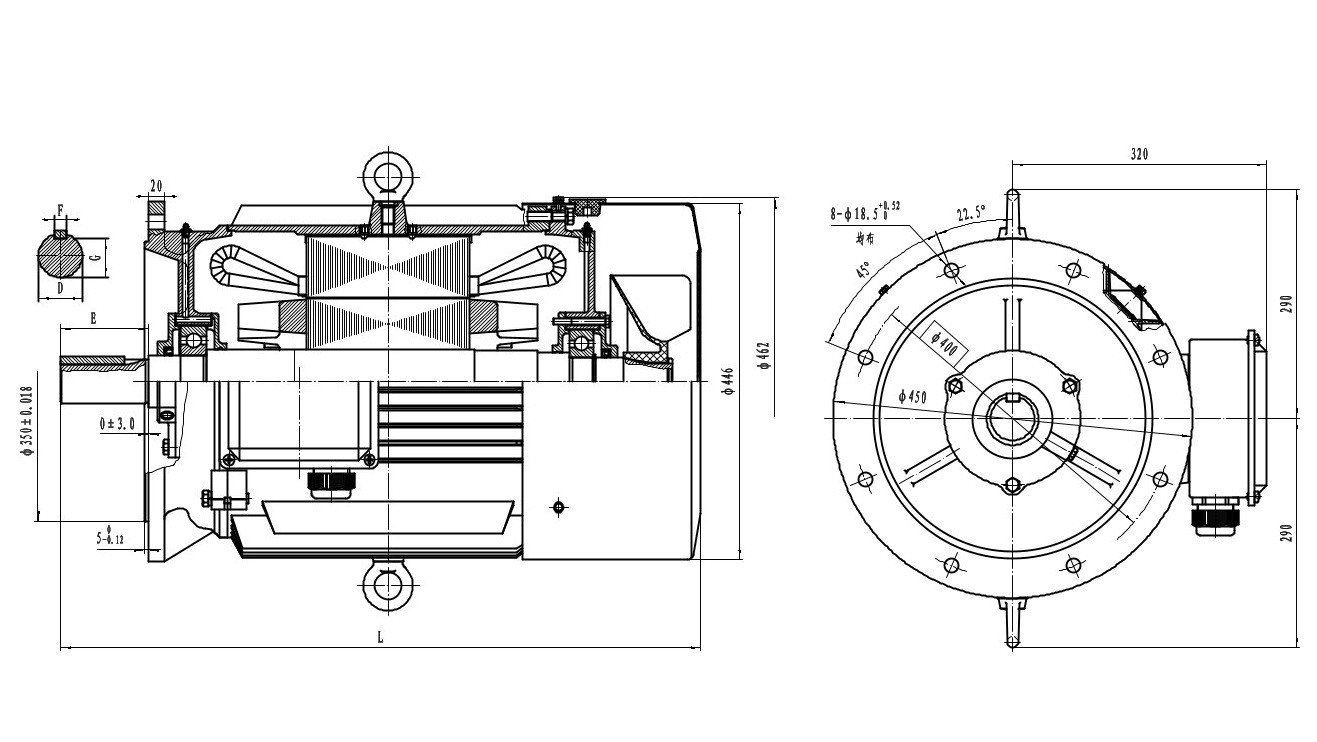
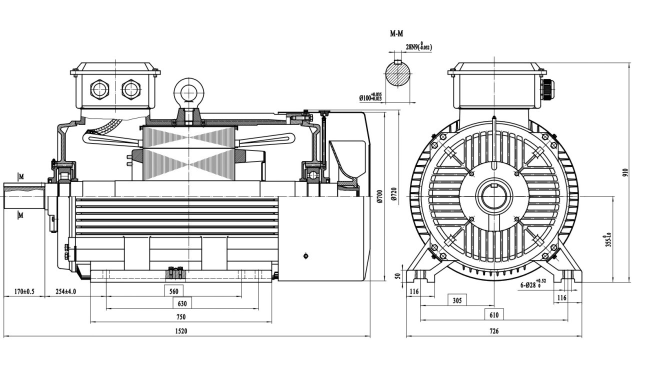
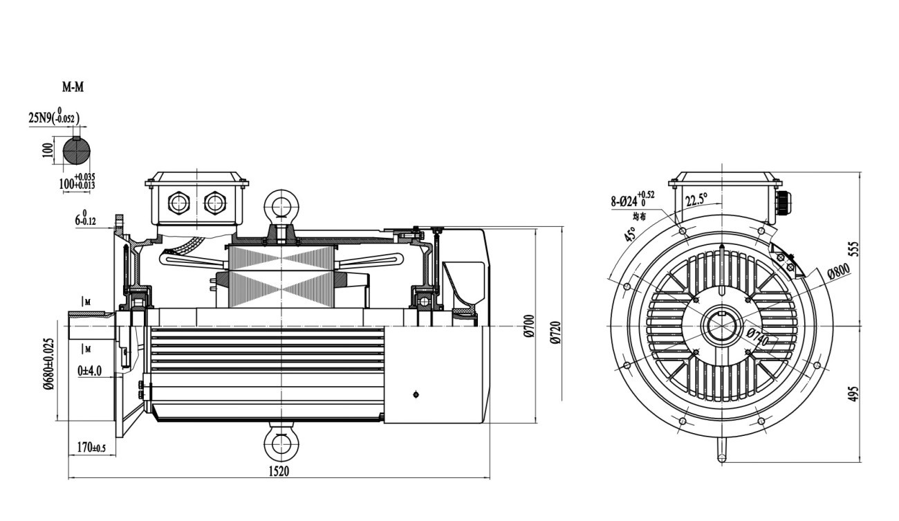
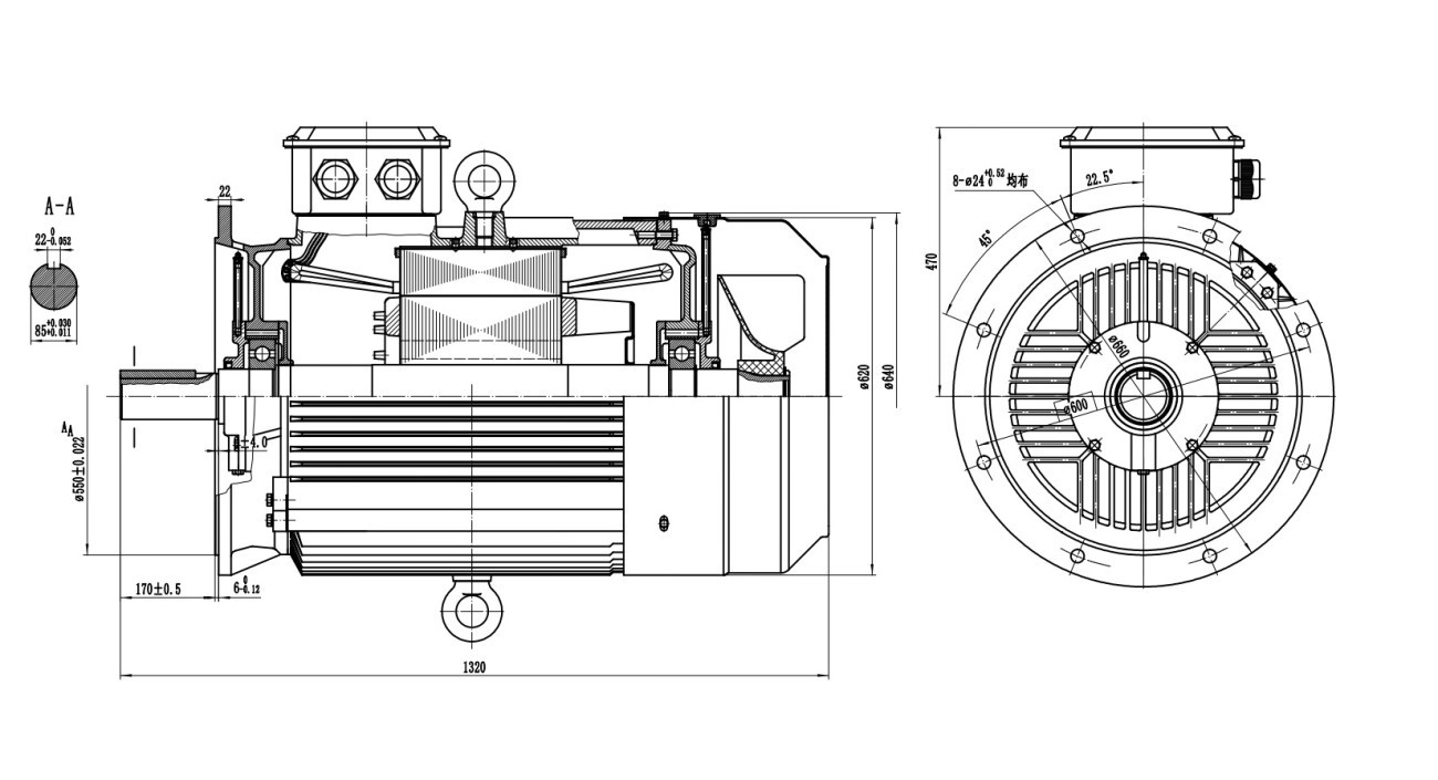
Our 2D outline drawings show the critical dimensions required for mechanical integration:
- Frame centre height and the overall length/height of the motor,
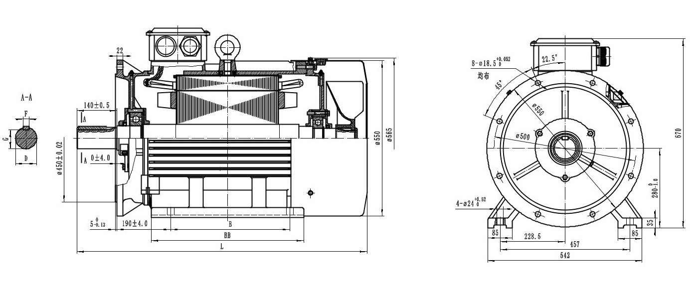
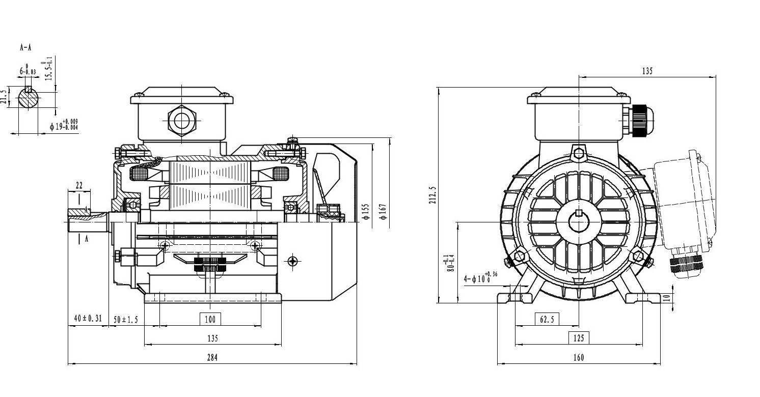
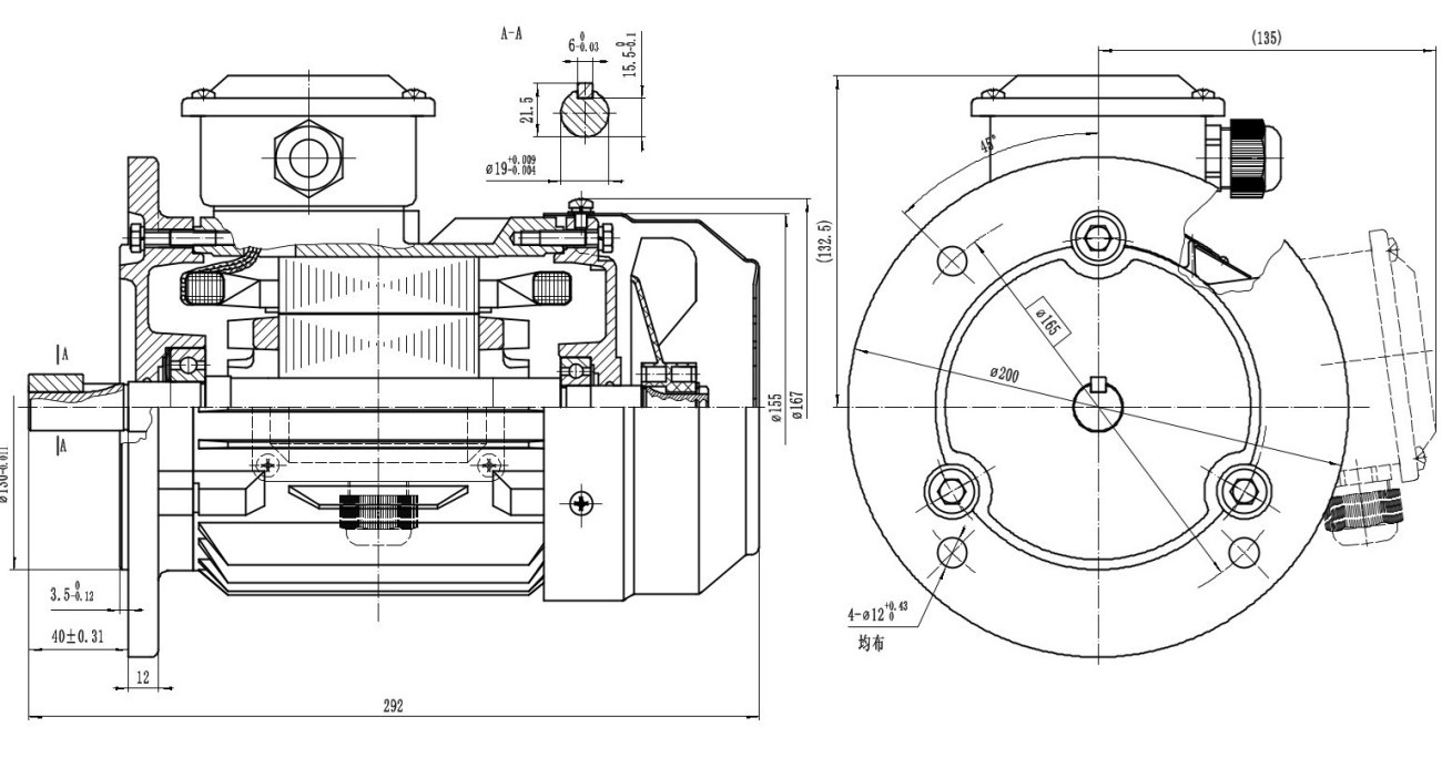
- Shaft diameter, shaft length and keyway dimensions (F, G, D in the section detail),
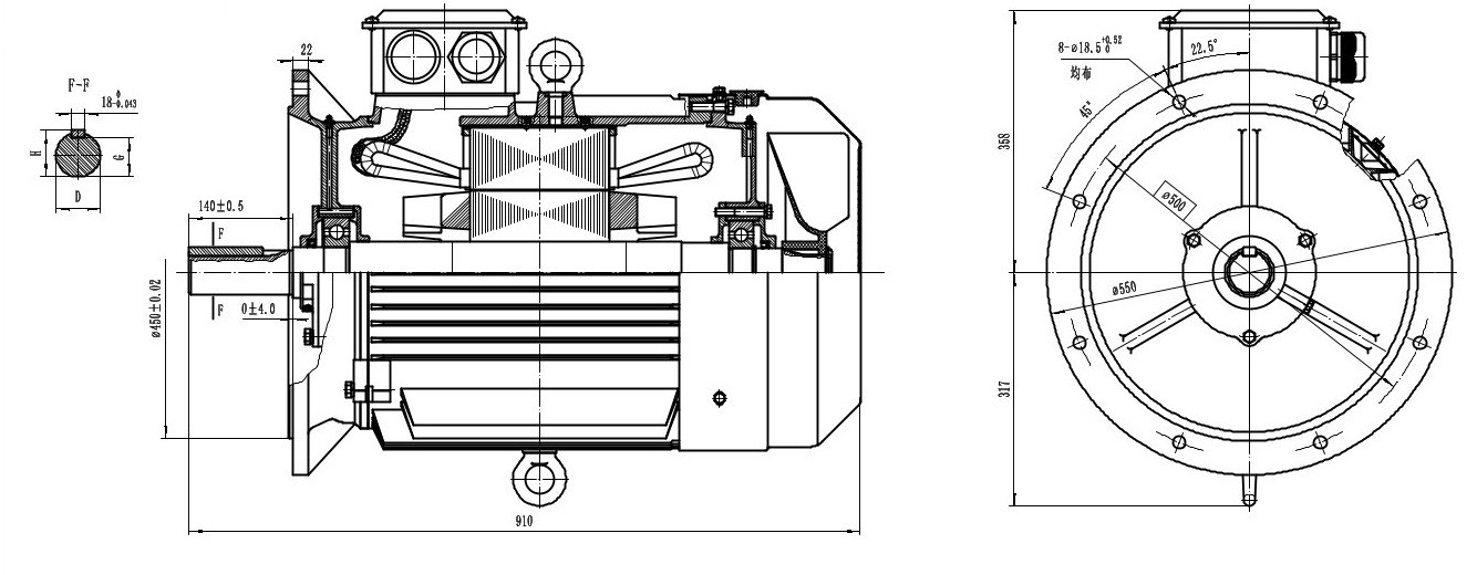
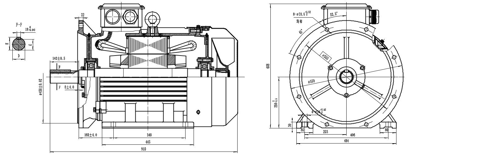
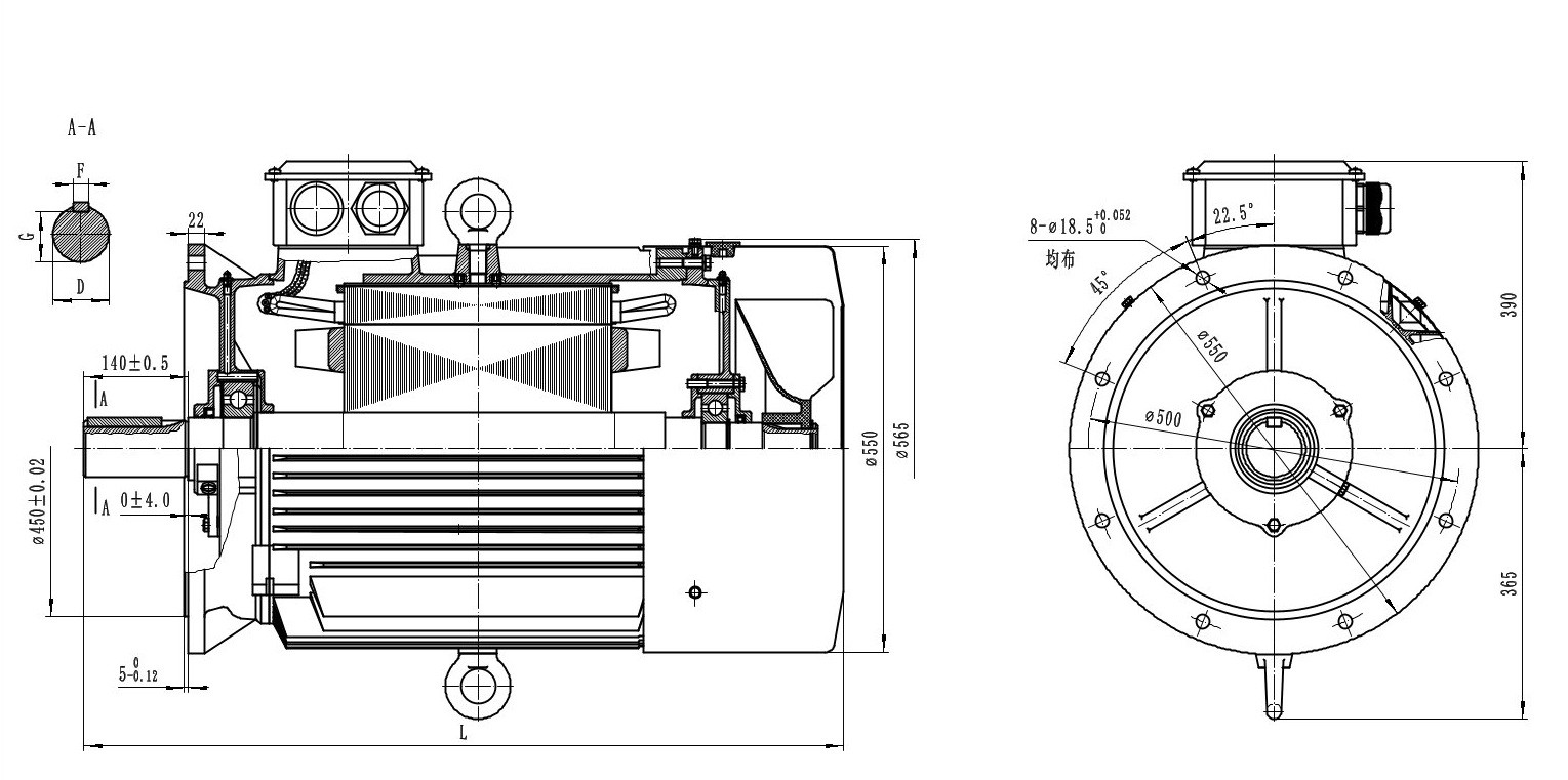
- Flange outer diameter, bolt circle diameter and the number/size of fixing holes (e.g. flange Ø800, bolt circle Ø740, 8 × Ø24 holes, evenly distributed),
- Foot hole spacing (for B3 foot mounting),
- Terminal box position and overall envelope dimensions.
Drawings by Mounting Type
The way the motor is connected determines which outline drawing you need. The most common mounting types are:
- B3 (foot-mounted): the motor is bolted to the foundation or chassis via its feet.
- B5 (flange-mounted): the motor is connected to the machine via the large flange at the front.
- B35 (foot + flange): both foot and flange connections are provided together.
Each mounting type has a different flange diameter, bolt circle and hole pattern; selecting the correct drawing is critical for mounting compatibility.
Who Uses These Drawings and How?
Project engineers use these drawings for plant layout, coupling selection, guard design and foundation calculation. Maintenance teams compare the dimensions of an existing motor one-to-one when sourcing a replacement. The tolerance values in our drawings (for example, shaft diameter tolerances) ensure safe assembly in precise mechanical connections.
Could Not Find Your Drawing?
If you cannot find the 2D drawing for the power, frame size or mounting type you need on this page, simply contact us. Our technical team will share the current dimensional drawing of the model you request.
If you also need the electrical data of the motor you selected — power, speed, current, efficiency and torque — see the DRG Motor Technical and Product Catalog 2026 and download the 32-page PDF free of charge.
Frequently Asked Questions
In which format are the 2D drawings provided?
The drawings are provided in PDF format, which can be easily viewed and printed. If you need a specific CAD format (DWG/DXF), you can contact our technical team.
Can I verify the dimensions before purchasing the motor?
Yes. That is exactly what 2D outline drawings are for; you can clearly verify the motor's compatibility with your machine, foundation or coupling on the drawing before purchase.