English
 Türkçe

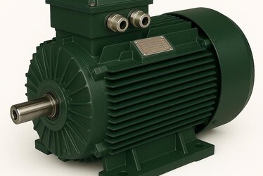
Flange-mounted electric motors bolt directly to machines such as pumps, gearboxes and fans, offering a far more compact mounting solution than foot-mounted bodies. The flange face on the front cover of these motors falls under two major standards: B5 and B14. At first glance both look like "a round mounting surface," but they differ significantly in flange diameter, hole type and the load they can carry. The real confusion arises from the hole type on the flange face: FF (clearance holes, through bolts) and FT (tapped holes, screwed-in bolts). At DRG Motor, this article explains in detail the FF and FT difference between B5 and B14 flanges, which one is correct for which application, and why these two types cannot be used interchangeably in the field.

What Is a Flange-Mounted Motor and Why Is It Preferred?
A flange-mounted motor has a flat mounting surface on the drive-end cover where the shaft exits. This surface bolts directly onto the body of the driven machine, forming a single integrated unit with no separate base or separate alignment procedure between the motor and the machine. The greatest advantage of a flange connection is that the shaft arrives factory-aligned with the machine axis; the motor seats in place without struggling with shaft and coupling alignment during field installation.
Flange-mounted motors stand out particularly in pump sets, gearbox inputs, vertically positioned fans and compact machine designs where space saving matters. You can find the overall framework for all mounting types in our article on B3, B5, B14 and B35 mounting types.
What Is a B5 Flange?
B5 is the standard mounting type for motors with a large-diameter flange. The flange is a plate wider than the body diameter, with holes arranged at equal intervals around its circumference. In a B5 flange the mounting bolts pass from the back toward the front; that is, the bolt is inserted from the motor side toward the machine.
Thanks to the large flange surface, B5 mounting spreads the motor's weight and the moment generated during operation over a wide area. For this reason B5 is preferred in medium and large power motors and in applications transmitting high torque. The most common flange type at gearbox inputs is B5.
What Is a B14 Flange?
B14 is a smaller flange, a plate close to the body diameter, generally near the motor body itself. In a B14 flange the holes are usually tapped; that is, the connection is made with bolts screwed in from the outside, from the machine toward the motor. The B14 flange is designed for lighter applications and is common on low-power motors.
The biggest advantage of B14 is that mounting can be done from the front of the motor; there is no need to remove the machine and pass a bolt from behind. This offers a practical solution for small pumps, small fans and light machine elements.
FF Hole Type: Clearance (Through) Flange
This is where the point installers most often confuse begins. While the flange type (B5/B14) determines the flange size, FF and FT determine the flange hole type. FF (free hole / clearance flange) is a flange with plain holes. The bolt passes freely through the hole and is tightened on the other side with a nut or against a tapped counter-surface. B5 flanges are typically FF: a large plate with bolts passing through the holes.
In the FF type, because the bolt runs all the way through the flange, the connection is very rigid and withstands high moments. This is why FF holes are preferred in heavy-duty gearbox and pump connections.

FT Hole Type: Tapped (Screwed) Flange
FT (tapped hole flange) is a flange with threaded holes. The bolt is screwed into the flange from the outside; no nut is needed on the other side. B14 flanges are typically FT: a small plate, threaded holes, front-mounted connection. The FT connection provides ease of service and maintenance because it allows front mounting without removing the machine.
However, because the thread depth of FT is limited, the axial and radial load it can carry is lower than FF. For this reason FT is limited to light and medium load applications.
B5/FF and B14/FT Comparison Table
| Feature | B5 (FF - Clearance) | B14 (FT - Tapped) |
|---|---|---|
| Flange diameter | Large (plate wider than body) | Small (plate close to body) |
| Hole type | Plain hole (bolt passes through) | Tapped hole (bolt screws in) |
| Connection direction | Back to front (motor to machine) | From front (machine to motor) |
| Load capacity | High torque and load | Light-medium load |
| Typical use | Gearbox, large pump, fan | Small pump, small fan, light machine |
| Ease of mounting | May require machine access | Practical front mounting |
| Nut requirement | Yes (through bolt) | No (screws into thread) |
Why Are Flange Diameter and Spigot Diameter Important?
Two diameters are critical in a flange connection: the bolt circle diameter (the circle on which the bolts sit) and the spigot diameter (the diameter of the central boss or recess of the flange). The spigot diameter is what centers the motor on the machine; this is how the shaft automatically aligns with the machine axis. The same frame size can be produced with flanges of different spigot and bolt circle diameters, so the compatibility of these dimensions with the machine must be verified before ordering.
To understand the standard relationship between frame size and flange dimensions, our article on the IEC frame size standard is a good starting point.
Why Can't B5 and B14 Be Used Interchangeably?
This is one of the most frequently asked questions. The bolt circle diameters, spigot diameters and hole types of B5 and B14 flanges differ. If a machine is designed for a B14 flange, a B5 motor cannot be bolted onto it; the holes match neither in diameter nor in type. The reverse is also true. For this reason, in motor selection the flange type is as binding a constraint as the power.
Although some conversions are possible with adapter flanges, this solution adds extra weight, an extra connection surface and alignment risk; it is not recommended in heavy applications.
What Happens When FF and FT Are Confused?
Both FF and FT flanges can exist in the same B5 dimension. On a motor that arrives as FT when FF was expected, the bolts have to be screwed into the flange; this means wrong bolt length, insufficient thread engagement and the risk of loosening. Conversely, if an FF flange arrives where FT was expected, the connection cannot be made at all because there is no place for a nut on the other side. For this reason, saying only "B5" when ordering is not enough; whether it is FF or FT must always be specified.
Which Flange for Which Application?
B5/FF is used almost always at gearbox inputs, because the gearbox transmits high torque and the large flange carries this load. When selecting motor-gearbox compatibility, the flange type must match the gearbox input flange.
In centrifugal pumps, both B5 and B14 can be seen depending on the pump size; B14/FT is common in small circulation pumps and B5/FF in large process pumps. In fans, B14 is preferred in vertically mounted small fans and B5 in large duct-type fans.
Evaluation in Terms of Axial and Radial Load
Flange selection is not just about hole compatibility, it is a matter of the load to be carried. The axial thrust created by a pump impeller or fan blade bears directly on the flange connection. B5/FF carries this load safely with its large surface and through bolts, while B14/FT struggles under high axial load due to its limited thread depth. When calculating the load, the bearing life of the motor must also be considered; our article on extending bearing life contains useful information on this subject.
The Relationship Between Mounting Position and Flange
Flange-mounted motors can be used in horizontal position (B5, B14), and can also be mounted vertically with the shaft facing down or up (such as V1, V3). In vertical mounting the flange carries the entire weight of the motor, so the flange dimension becomes even more critical. To select the correct mounting position, you can review our article on mounting type selection.
Protection Class and Flange Connection
On vertically mounted flange motors, if the shaft is on the upper side, the likelihood of water or liquid dripping onto it increases. In this case the motor's IP protection class and, if necessary, the selection of a drip cover become important. The sealing of the flange face also comes into play in some pump applications.
What to Specify When Ordering
To purchase the correct flange motor, the following information must be given clearly: mounting type (B5 or B14), hole type (FF or FT), flange bolt circle diameter, spigot diameter, frame size and power. These must match one-to-one with their counterparts on the machine. A single missing dimension means a motor that does not fit in the field.

How to Read B5 and B14 Size Codes?
Flange dimensions are usually indicated with a number next to the flange type; this number refers to the bolt circle diameter. For example, as the bolt circle diameter of a flange increases, so does its load capacity. Because different flange diameters can be offered even within the same frame size, looking only at the motor power is not enough; the flange bolt circle, spigot diameter and number of holes must be evaluated together with the machine. Reading these codes correctly eliminates the risk of an incorrect order.
Number of Holes and Bolt Pattern
B5 and B14 flanges generally have four holes, arranged symmetrically with respect to the flange center. The number and spacing of the holes must match the flange of the counter machine exactly. The symmetrical pattern also allows the motor to be mounted at different angles (for example, with the terminal box facing a different direction). The terminal box orientation is a practical detail to plan before mounting.
Cleanliness of the Flange Face and Mounting Quality
For the flange connection to seat properly, both the motor flange and the machine surface must be clean, burr-free and flat. A speck of dust, paint residue or burr on the surface causes the shaft to run off axis and creates vibration. Checking the surfaces before mounting prevents bearing and coupling problems that would otherwise appear later.
Flange Material and Strength
The flange face is generally produced from the same material as the motor body, in aluminum or cast iron. Cast iron flanges are more rigid and are preferred in high-torque and vibrating applications; aluminum flanges stand out with their light weight in small pump and fan sets. The flange material must be evaluated together with the load to be carried and the operating environment.
Vibration and Loosening of the Flange Connection
A flange connection can loosen over time due to vibration. Especially in FT (tapped) connections, because thread engagement is limited, it is important to tighten the bolts to the correct torque value and to use a thread-locking application when necessary. Regular checks preserve the safety of the connection. Our article on electric motor maintenance steps provides guidance on the general maintenance schedule.
Choosing Between Flange and Foot Mounting
In some applications the B35 type, which has both a flange and feet, is preferred; this motor is both bolted to the machine with a flange and supported by a base. In very heavy or long-overhung applications, B35 reduces the load borne by the flange. A pure flange (B5/B14) solution, on the other hand, provides space saving and compactness. The choice is made according to the machine's load distribution.
Using a Flange Motor With a Frequency Inverter
Flange motors are frequently used in pump and fan systems driven by a frequency inverter. In these variable-speed systems the rigidity of the flange connection is also important in terms of resonance and vibration. The correct flange supports quiet and vibration-free operation in an inverter-driven system.
Pump Sets and Flange Selection
In centrifugal pumps the motor is bolted directly to the pump body with a flange and the shaft is transferred to the pump shaft with a coupling. Here the flange type is determined according to the impeller diameter and the suction-discharge conditions of the pump. While B14/FT is a practical solution in small circulation pumps, B5/FF is preferred in high-flow process pumps. Our article on electric motor selection for water pumps provides detailed guidance for water applications.
Flange Motors in Crane and Lifting Systems
In lifting and travel mechanisms the motor is generally connected to the gearbox with a flange. Because these applications involve high torque and sudden load changes, rigid flange connections such as B5/FF are preferred. In these systems, which often require a brake motor, the load capacity of the flange is critical. You can find details on the subject in our article on crane and lifting motors.
Two-Speed Motors and Flange Use
In some pump and fan applications, motors that run at two different speeds are used. Two-speed electric motors can also be produced in a flange body; here the flange type is selected considering the axial load and vibration generated at high speed. The sudden moment created during a speed change requires the flange connection to be sufficiently rigid.
Spare Parts and Ease of Replacement
Because standard B5 and B14 flange dimensions are defined within the IEC framework, when a motor of a given size fails, it can be replaced with another motor of the same flange and frame size. This standardization prevents long production line downtime. However, before replacement it must be verified that the new motor's flange type (FF/FT), spigot diameter and shaft dimension are the same as the old one; even a single dimensional difference can make replacement impossible.
Cooling and Flange Position
The vast majority of flange motors are cooled by a fan at the rear. When the motor is integrated with the machine through a flange, it should not be forgotten that heat from the machine can also be conducted to the motor. Especially in pumps carrying hot fluid, heat coming through the flange can raise the motor temperature. In this case the insulation class and cooling conditions must be re-evaluated.
DRG Motor for the Right Flange Solution
In flange motor selection, the difference between B5/FF and B14/FT often determines whether the installation succeeds. At DRG Motor, within our AC asynchronous motor range we match different flange and hole types to the load and torque needs of your application. Share your machine's flange dimensions with us; from a gearbox input to a pump set, let us determine the right flange type together. For more technical information you can review our article on industrial electric motors, and contact DRG Motor for your project.