 English
 Le français
 Türkçe

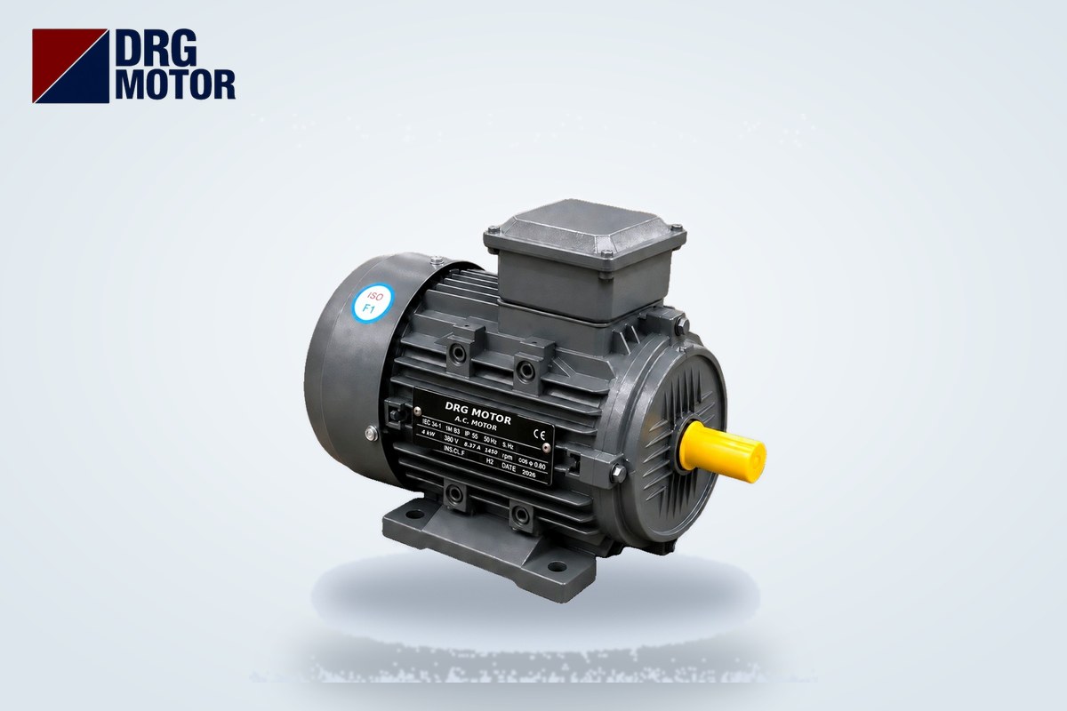

B5 motor flange dimensions depend on the frame size: according to the DRG catalogue, a 63 frame has a flange outside diameter P of 140 mm, a bolt circle M of 115 mm and a spigot diameter N of 95 mm, a 112M frame has P 250 / M 215 / N 180 mm, frames 160M to 180L have P 350 / M 300 / N 250 mm, and the largest 355M–355L frames have P 800 / M 740 / N 680 mm. The table below gives the B5 (FF) flange dimensions and the shaft size of every frame from 63 to 355 on a single row, so if you know the frame of your motor you can read its flange directly.
The flange is set by the frame, not by the motor's power. That is why many power ratings share the same flange: the FF165 flange is common to frames 80, 90S and 90L, and the FF300 flange covers four frames from 160M to 180L. The shaft diameter, however, can change within the same flange, especially on frames 225M and above, where the shaft of a 2-pole motor is thinner than that of a 4-pole motor. You can list the motors that match each frame by power, speed and frame on our Buy Electric Motors Online page; the B5, B35 or B14 mounting option is stated in the order note.
This article focuses only on the dimension table and on how to verify the dimensions on site. For how to read a gearbox input and the logic of choosing between B5 and B14, see our article on choosing a flange motor for a gearbox.
B5 Flange Dimensions Table: Frames 63–355 (mm)
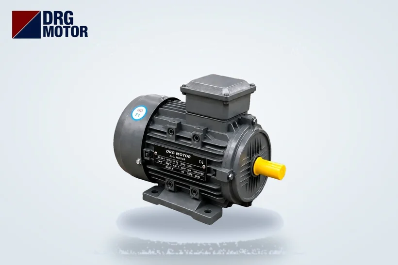
The values come from the IM B5 large-flange frame table in the DRG Motor catalogue; all dimensions are in mm. Adjacent frames with exactly the same flange and shaft values (e.g. 90S / 90L) are shown on one row. On frames 225M and above, 2-pole motors and motors with 4 or more poles have different shafts, so these frames are listed on two separate rows.
| Frame | Poles | Flange | M | N | P | S | T | LA | Shaft D×E | Key F |
|---|---|---|---|---|---|---|---|---|---|---|
| 63 | 2, 4, 6 | FF115 | 115 | 95 | 140 | 10 | 3 | 10 | 11×23 | 4 |
| 71 | 2, 4, 6 | FF130 | 130 | 110 | 160 | 10 | 3.5 | 10 | 14×30 | 5 |
| 80 | 2, 4, 6, 8 | FF165 | 165 | 130 | 200 | 12 | 3.5 | 12 | 19×40 | 6 |
| 90S / 90L | 2, 4, 6, 8 | FF165 | 165 | 130 | 200 | 12 | 3.5 | 12 | 24×50 | 8 |
| 100L | 2, 4, 6, 8 | FF215 | 215 | 180 | 250 | 14.5 | 4 | 13 | 28×60 | 8 |
| 112M | 2, 4, 6, 8 | FF215 | 215 | 180 | 250 | 14.5 | 4 | 14 | 28×60 | 8 |
| 132S | 2, 4, 6, 8 | FF265 | 265 | 230 | 300 | 14.5 | 4 | 14 | 38×80 | 10 |
| 132M | 4, 6, 8 | FF265 | 265 | 230 | 300 | 14.5 | 4 | 14 | 38×80 | 10 |
| 160M / 160L | 2, 4, 6, 8 | FF300 | 300 | 250 | 350 | 18.5 | 5 | 15 | 42×110 | 12 |
| 180M | 2, 4, 8 | FF300 | 300 | 250 | 350 | 18.5 | 5 | 15 | 48×110 | 14 |
| 180L | 4, 6, 8 | FF300 | 300 | 250 | 350 | 18.5 | 5 | 15 | 48×110 | 14 |
| 200L | 2, 4, 6, 8 | FF350 | 350 | 300 | 400 | 18.5 | 5 | 17 | 55×110 | 16 |
| 225S | 4, 8 | FF400 | 400 | 350 | 450 | 18.5 | 5 | 20 | 60×140 | 18 |
| 225M | 2 | FF400 | 400 | 350 | 450 | 18.5 | 5 | 20 | 55×110 | 16 |
| 225M | 4, 6, 8 | FF400 | 400 | 350 | 450 | 18.5 | 5 | 20 | 60×140 | 18 |
| 250M | 2 | FF500 | 500 | 450 | 550 | 18.5 | 5 | 22 | 60×140 | 18 |
| 250M | 4, 6, 8 | FF500 | 500 | 450 | 550 | 18.5 | 5 | 22 | 65×140 | 18 |
| 280S | 2 | FF500 | 500 | 450 | 550 | 18.5 | 5 | 22 | 65×140 | 18 |
| 280S | 4, 6, 8 | FF500 | 500 | 450 | 550 | 18.5 | 5 | 22 | 75×140 | 20 |
| 280M | 2 | FF500 | 500 | 450 | 550 | 18.5 | 5 | 22 | 65×140 | 18 |
| 280M | 4, 6, 8 | FF500 | 500 | 450 | 550 | 18.5 | 5 | 22 | 75×140 | 20 |
| 315S | 2 | FF600 | 600 | 550 | 660 | 24 | 6 | 22 | 65×140 | 18 |
| 315S | 4, 6, 8, 10 | FF600 | 600 | 550 | 660 | 24 | 6 | 22 | 85×170 | 22 |
| 315M | 2 | FF600 | 600 | 550 | 660 | 24 | 6 | 22 | 65×140 | 18 |
| 315M | 4, 6, 8, 10 | FF600 | 600 | 550 | 660 | 24 | 6 | 22 | 85×170 | 22 |
| 315L | 2 | FF600 | 600 | 550 | 660 | 24 | 6 | 22 | 65×140 | 18 |
| 315L | 4, 6, 8, 10 | FF600 | 600 | 550 | 660 | 24 | 6 | 22 | 85×170 | 22 |
| 355M | 2 | FF740 | 740 | 680 | 800 | 24 | 6 | 25 | 75×140 | 20 |
| 355M | 4, 6, 8, 10 | FF740 | 740 | 680 | 800 | 24 | 6 | 25 | 100×170 | 25 |
| 355L | 2 | FF740 | 740 | 680 | 800 | 24 | 6 | 25 | 75×140 | 20 |
| 355L | 4, 6, 8, 10 | FF740 | 740 | 680 | 800 | 24 | 6 | 25 | 100×170 | 25 |
No values are given in this table for the B14 small flange: on a B14 flange the holes are tapped and the dimensions differ from B5. If you need B14 flange dimensions, write to us with the frame size; our article on the FF and FT hole difference on B5 and B14 flanges explains the difference in hole type.
What Do the Letters in the Table Measure?
Looking at the motor, the catalogue letters correspond as follows. Separating which value is a "diameter" and which is a "length" before you start measuring prevents a wrong match:
- P – flange outside diameter: The outermost diameter of the flange disc. The mating part must have room for this diameter.
- M – bolt circle diameter: The diameter of the circle through the centres of the bolt holes. The flange name comes from this value: if M is 215, the flange is FF215.
- N – spigot (pilot) diameter: The ring-shaped shoulder protruding from the flange face. This is the dimension that aligns the motor axially with the mating part.
- S – hole diameter: The diameter of the clearance (untapped) bolt hole in the B5 flange.
- T – spigot length: The height of the pilot shoulder above the flange face.
- LA – flange thickness: The dimension you need when choosing the bolt length.
- D×E and F: Shaft diameter × shaft length and key width.
Measuring the Flange of Your Motor with a Caliper
Four measurements are enough to find which flange a motor with an unreadable nameplate, or a mating part, corresponds to. Take the measurements on a surface cleaned of paint and rust, from at least two different directions.
P and N: diameters measured directly
The flange outside diameter P is taken directly with the outside jaws of the caliper. For the spigot diameter N, measure the outside diameter of the pilot shoulder; on the mating part (gearbox cover, pump bell housing) you look for the same value as the inside diameter of the recess. If the N you measured does not match a row in the table exactly, measure again before rounding; the differences between neighbouring flanges are clear, such as 130 versus 180 or 230 versus 250.
M: calculating the bolt circle
You cannot measure the hole centre directly, but you can calculate it from two opposite holes. Measure the distance between the inner edges of two opposite holes and the distance between their outer edges; the average of the two is M. On a motor with a 112M frame (M 215, S 14.5) you measure 200.5 mm between the inner edges and 229.5 mm between the outer edges; their average is 215 mm. On a four-hole flange where you can only reach two adjacent holes, multiply the centre-to-centre distance by √2: for FF215, the distance between two adjacent hole centres is about 152 mm.
T and LA: length dimensions
Measure the pilot shoulder height T with the depth rod of the caliper and the flange thickness LA at the edge of a hole. If the recess depth in the mating part is less than T, the flange face will not seat fully; LA determines the bolt length.
Frames Sharing the Same Flange and Their Power Ranges
The question most often asked on site is "what kW motor fits this flange?". The table below groups the standard models in the online store by flange. All the ratings on the same row carry the same P, M and N dimensions; for the shaft size, however, you need to go back to the first table.
| Flange | Frames | 2-pole (kW) | 4-pole (kW) | 6-pole (kW) |
|---|---|---|---|---|
| FF115 | 63 | 0.25 | — | — |
| FF130 | 71 | 0.37–0.55 | 0.25–0.37 | 0.25 |
| FF165 | 80, 90S, 90L | 0.75–2.2 | 0.55–1.5 | 0.37–1.1 |
| FF215 | 100L, 112M | 3–4 | 2.2–4 | 1.5–2.2 |
| FF265 | 132S, 132M | 5.5–7.5 | 5.5–7.5 | 3–5.5 |
| FF300 | 160M, 160L, 180M, 180L | 11–22 | 11–22 | 7.5–15 |
| FF350 | 200L | 30–37 | 30 | 18.5–22 |
| FF400 | 225S, 225M | 45 | 37–45 | 30 |
| FF500 | 250M, 280S, 280M | 55–90 | 55–90 | 37–55 |
| FF600 | 315S, 315M, 315L | 110–200 | 110–200 | 75–132 |
| FF740 | 355M, 355L | 250–315 | 250–315 | 160–250 |
The table is useful when increasing power: for example, if 5.5 kW is needed instead of the DRG-112M-4 (4 kW, 1500 rpm), a 4-pole motor moves to the 132S frame, i.e. the FF265 flange; the flange and the shaft change together. Conversely, 4-pole motors from 2.2 to 4 kW use the same FF215 flange and 28×60 shaft on frames 100L and 112M.
Matching with a Gearbox, Pump or Fan Flange
When the flange of the mating part fits a row in the table, matching is not yet finished. There are two typical cases where the flange fits but the shaft does not:
- Same flange, different frame: Frames 80 and 90 carry the same FF165 flange, but the shafts are 19×40 and 24×50. A gearbox bushing or coupling hub is machined to the shaft diameter.
- Same frame, different poles: On the 225M frame the flange is FF400; the 2-pole DRG-225M-2 has a 55×110 shaft, while the 4-pole DRG-225M-4 has a 60×140 shaft. On the 315 frame the difference is larger: 65×140 for 2 poles and 85×170 for 4 poles and above.
In pump applications a bell housing and a coupling usually sit between the motor and the pump. The motor side of the bell housing is selected according to the motor's B5 flange (P, M, N, S), and the motor-side coupling hub according to D and F. In fan applications, if the fan hub sits directly on the shaft, the shaft length E must be considered together with the hub length. If you are working out power and torque, our electric motor calculators page helps you find the right kW before choosing the flange.
Checklist Before Ordering a Flange Motor
- State the motor's IEC frame (e.g. 112M) and number of poles; kW alone is not enough.
- Measure P, M and N on the mating part and compare them with the row in the table.
- Check the hole type: clearance holes mean B5 (FF), tapped holes mean B14.
- Match the shaft D×E and key F with the bushing or coupling hub.
- On frames 225M and above, confirm separately whether the motor is 2-pole or 4-pole.
- If feet will also be used, order B35 (feet + flange).
- Write the mounting type clearly in the order note, e.g. "B5, FF215, 28×60 shaft".
Motors Suitable for a B5 Flange: Example Models
The cast iron models below represent different flange groups. For other ratings with the same frame, you can search by frame among the 120 models in our online store.
- DRG-90L-4 – 1.5 kW – 1500 rpm – 90L cast iron frame
- DRG-112M-4 – 4 kW – 1500 rpm – 112M cast iron frame
- DRG-132M-4 – 7.5 kW – 1500 rpm – 132M cast iron frame
- DRG-160L-4 – 15 kW – 1500 rpm – 160L cast iron frame
- DRG-225M-4 – 45 kW – 1500 rpm – 225M cast iron frame
- DRG-225M-2 – 45 kW – 3000 rpm – 225M cast iron frame
Click to see current prices and order these motors nowSEE PRICES →
Frequently Asked Questions
Do B5 flange dimensions change with kW?
No, they change with the frame. For example, in 4-pole versions 11 kW and 22 kW motors have different power ratings, but because of their 160M and 180L frames they carry the same FF300 flange (P 350, M 300, N 250 mm).
Which motor does an FF165 flange fit?
The FF165 flange is used on frames 80, 90S and 90L. Among the store models this corresponds to 0.75–2.2 kW in 2-pole, 0.55–1.5 kW in 4-pole and 0.37–1.1 kW in 6-pole versions; the shaft is 19×40 on the 80 frame and 24×50 on the 90 frame.
How is the spigot diameter of a B5 flange measured?
Measure the outside diameter of the pilot shoulder on the motor flange with a caliper from two different directions and compare it with column N in the table. On the mating part, the same value is the inside diameter of the recess.
Why is there no B14 flange dimension table?
On the B14 small flange the holes are tapped and the dimensions differ from the B5 table; the values in this article apply only to the B5 large flange. For B14 dimensions, simply write to us with the motor frame.
To determine the right frame together using the dimensions of your gearbox, pump or bell housing, call +90 (542) 666 11 11, write to [email protected] or use our contact page. A motor whose dimensions are already known can be ordered directly from the Buy Electric Motors Online page.