 English
 Le français
 Türkçe





A start-stop self-holding circuit is the most basic contactor control for a three-phase motor: one button starts it, another stops it. A short press on start pulls in contactor K1; because K1’s own 13-14 auxiliary contact is wired in parallel with the start button, the coil stays energised after the button is released. When the stop button or the overload contact opens that path, the hold is lost and the motor stops.
Safety notice: This content is for technical information only. Wiring, measurement and commissioning must be carried out by qualified electrical personnel, following lock-out and verification of de-energised state, and in line with the motor and device manufacturer's documentation.
This article walks through the power side, the control side, indicator lamps, push-button station wiring and the timing diagram. All drawings are examples; terminal names vary by device, and the device’s own wiring diagram always prevails.
What components make up a start-stop circuit?
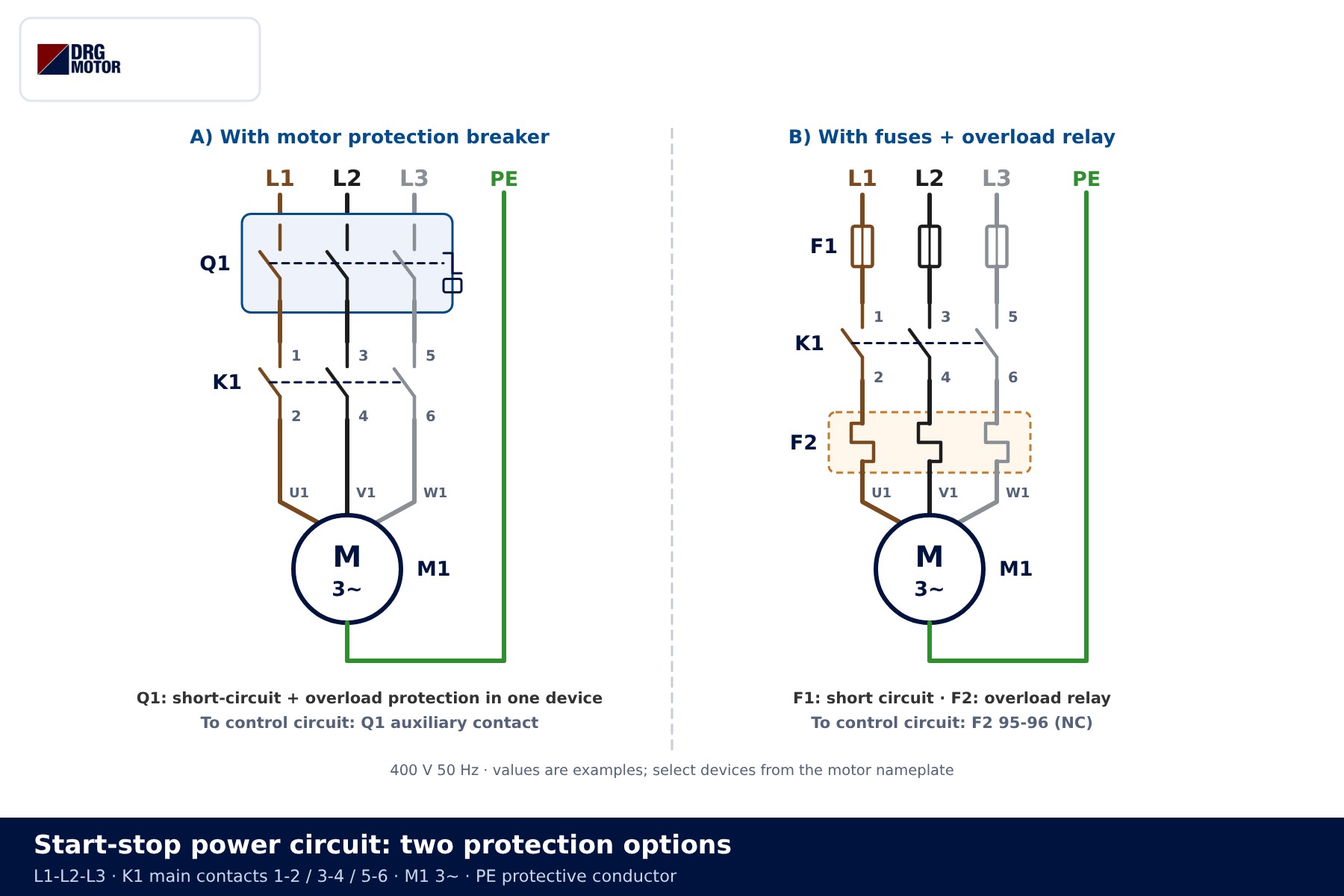
The circuit has two parts. The power circuit carries motor current: L1, L2 and L3 pass through a protective device and K1’s main contacts to reach the motor. The control circuit uses a small current to operate the K1 coil. On the power side there are two common layouts: a Q1 motor protection breaker that combines short-circuit and overload protection, or F1 fuses together with an F2 overload relay. The difference is explained in our article on thermal relay vs motor protection breaker.
| Component | Terminals | Role in the circuit |
|---|---|---|
| Q1 motor protection breaker | 1-2 / 3-4 / 5-6 + auxiliary contact | Short-circuit and overload protection in one device (option A) |
| F1 fuses | one per phase | Protect the power circuit against short circuits (option B) |
| F2 overload relay | main terminals + 95-96 NC, 97-98 NO | Opens the control circuit on overload and can drive a fault lamp |
| F3 control fuse | single pole | Protects the control wiring against short circuits |
| S0 stop button | 11-12 NC | Breaks the coil current as soon as it is pressed |
| Start button | 13-14 NO | Feeds the coil only while it is held down |
| K1 contactor | A1-A2 coil, 1…6 main, 13-14 auxiliary | Connects the motor to the supply; 13-14 provides self-holding |
| M1 motor | U1 V1 W1 + PE | Three-phase induction motor, star or delta on the terminal board according to the nameplate |
The order never changes: short-circuit protection first, then the contactor, then overload protection, then the motor. For sizing, use the overload, fuse and contactor selection tool; how to read contactor ratings is covered in motor panel contactor selection.
Control circuit and how self-holding works
Read the control circuit from top to bottom like a ladder. The upper rail is L (230 V AC in the example), the lower rail is N. Current passes the F3 control fuse, the 95-96 contact of F2 and the 11-12 contact of stop button S0, then splits at a junction. One branch goes through the start button, the other through K1’s 13-14 contact; the two branches rejoin at coil terminal A1, and A2 returns to N.
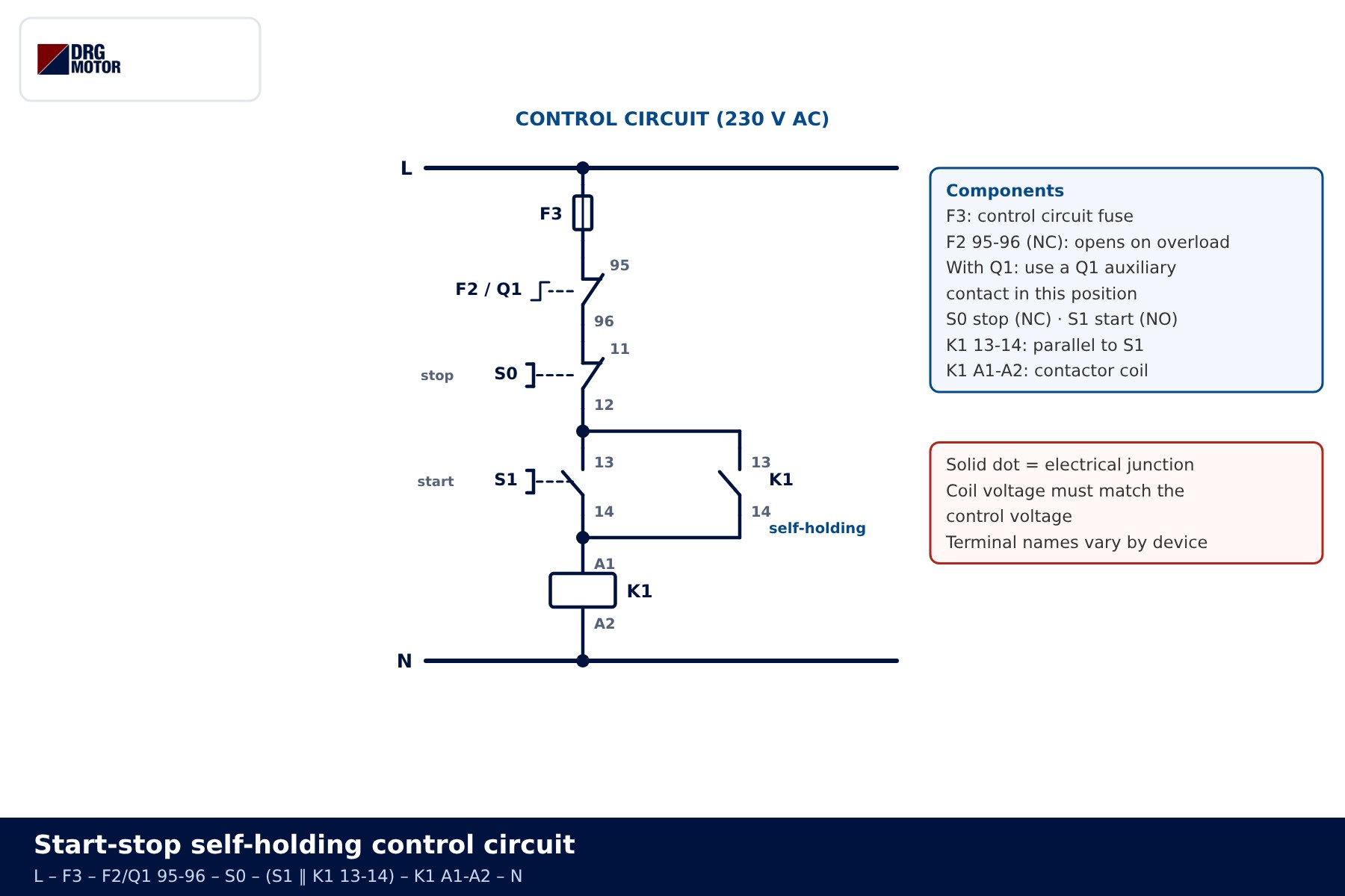
That parallel branch is the “self-holding” or “latching” path. The start button only gives the coil its first pulse; as soon as K1 pulls in, its 13-14 contact closes and creates a second supply path to the coil. From then on the start button no longer matters. The only way to break the hold is to open one of the series NC contacts: stop button S0, F2 95-96 or, with option A, the auxiliary contact of Q1.
Stop and protection contacts are normally closed for a safety reason: if a wire breaks or a terminal works loose, the circuit opens and the motor stops. When Q1 is used, wire its auxiliary contact into the control circuit. Otherwise K1 stays in when Q1 trips, and the motor can restart on its own as soon as Q1 is switched back on.
Note: S0 is an ordinary stop button. Emergency stop is a separate safety function; it needs a latching mushroom-head device and a circuit designed from the machine’s risk assessment.
📄 Download Wiring Diagram PDF A4 printable PDF of the diagrams and tables (no sign-up)
Click to see current electric motor prices and order nowSEE PRICES →
Step-by-step operating sequence
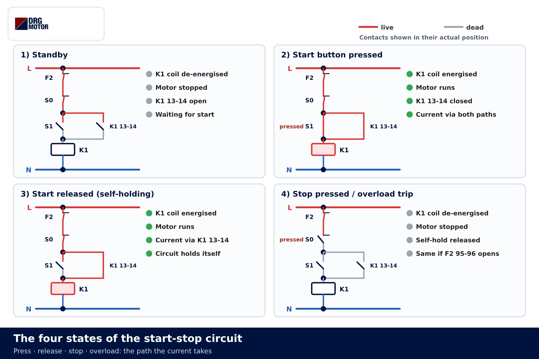
- Standby: F2 and S0 are closed, the start button and K1 13-14 are open. Both paths to the coil are broken, so K1 is off and the motor is stopped.
- Start pressed: the coil is fed through the start button. K1 pulls in: the main contacts connect the motor, and 13-14 closes. For this short moment current flows through both branches.
- Start released: the spring opens the button; the coil is now fed only through K1 13-14. The circuit holds itself and the motor keeps running.
- Stop pressed: S0 11-12 opens and the coil loses its only supply path. K1 drops out, 13-14 opens and the hold is released. Letting go of stop does not restart the motor.
- Overload trip: F2 95-96 opens; the result is the same as pressing stop. Resetting the relay does not pull K1 back in; a new start command is needed.
- Supply lost and restored: K1 drops out when the voltage disappears and the hold is lost. When the supply returns the motor stays stopped. This is the most valuable feature of self-holding: it prevents unexpected restarts.
State table and timing diagram
The table and drawing below show the state of each contact and the coil at every step. Comparing your measurements with this table speeds up fault-finding.
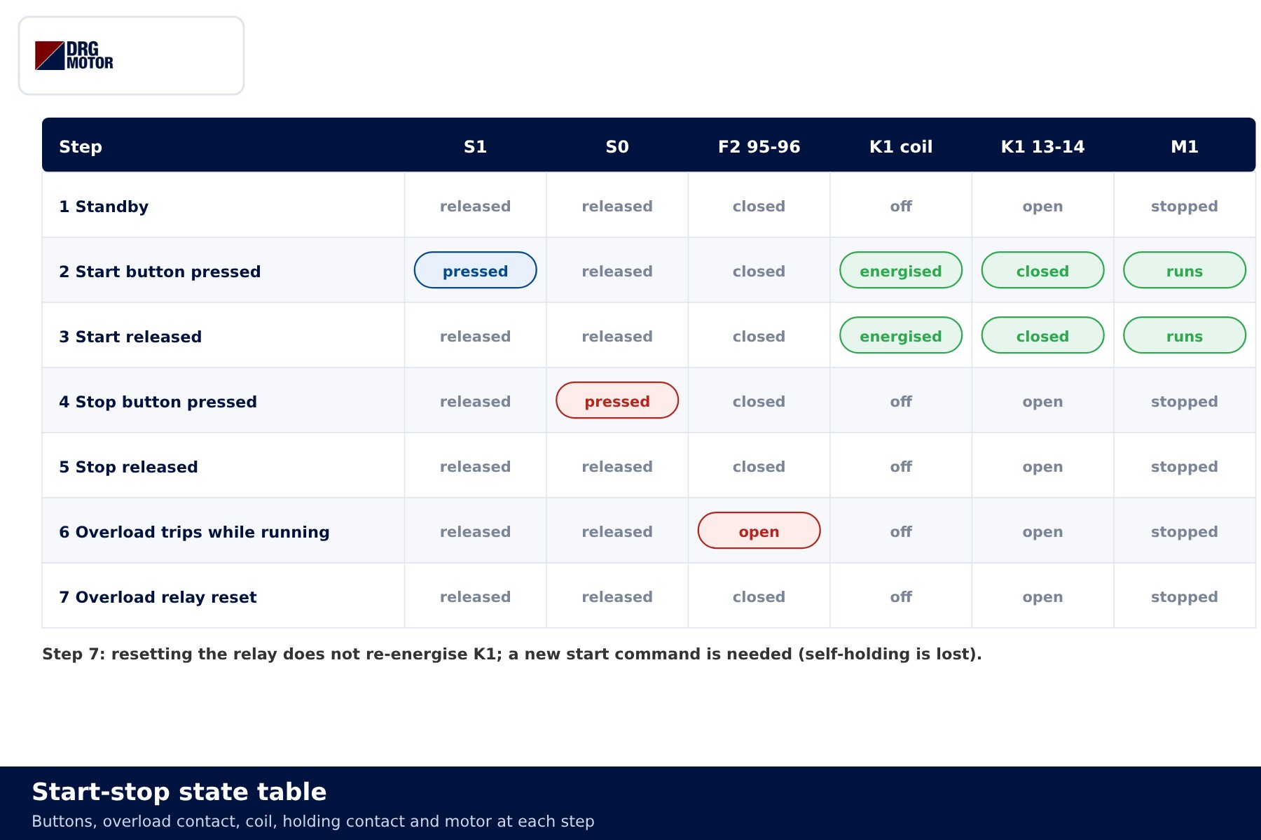
| State | K1 coil | K1 13-14 | Motor |
|---|---|---|---|
| Standby | off | open | stopped |
| Start button held | energised | closed | runs |
| Start released | energised (held) | closed | runs |
| Stop button pressed | off | open | stopped |
| Overload trip | off | open | stopped |
| Supply lost and restored | off | open | stopped, waits for start |
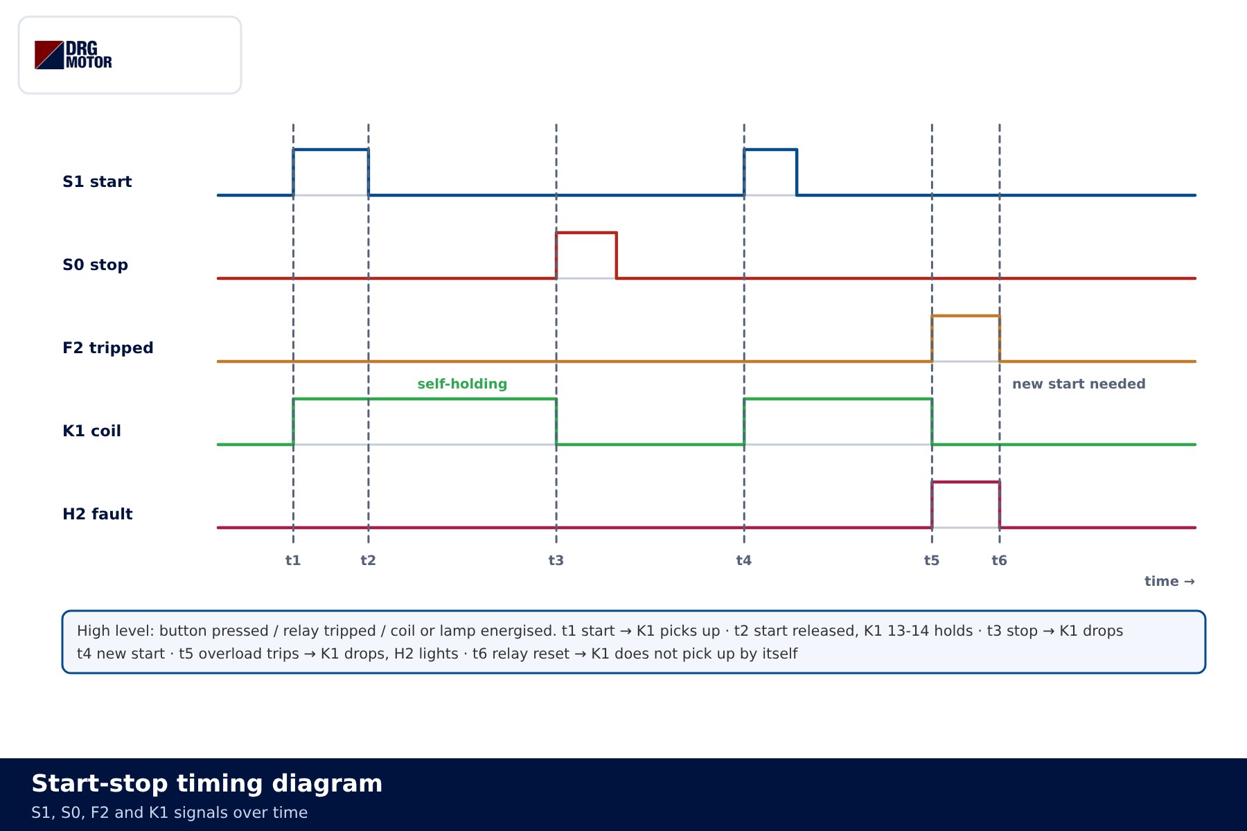
In the timing diagram a high level means “button pressed”, “relay tripped” or “coil energised”. Notice that the start signal is only a short pulse, while K1 stays high until stop arrives; that is self-holding in one picture. At t5 the overload trips and K1 drops; at t6 the relay is reset but K1 does not pull in again.
Adding running and fault lamps
Two indicator lamps answer the first question on site: is the motor running, and if it stopped, why? In the optional diagram, H1 “running” is fed through a second NO auxiliary contact of K1 (53-54 in the example), and H2 “fault” through the 97-98 NO contact of F2. When the relay trips, 95-96 opens and 97-98 closes, so the motor stops and the fault lamp lights at the same time.
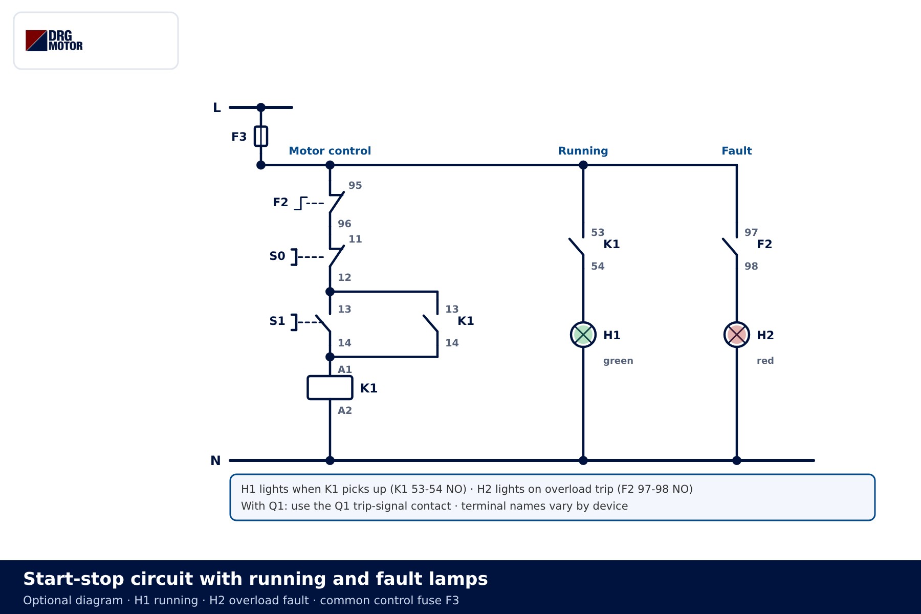
Lamp voltage must match the control voltage. With Q1, the fault signal comes from the breaker’s signalling contact; whether it exists and how it is numbered depends on the device. Lamps get their own rungs and are never tied into the holding branch.
3-wire connection to a push-button station
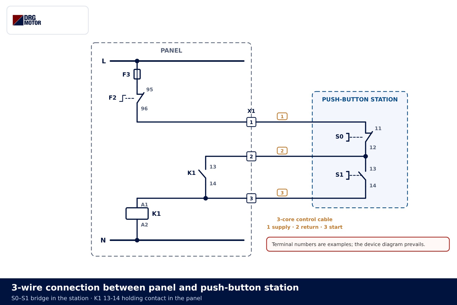
The buttons are often in a separate station next to the machine. The stop and start buttons are then wired in series inside the station and a three-core cable to the panel is enough: core 1 is the supply (stop input), core 2 the stop output / start input, core 3 the start output. The K1 13-14 holding contact sits in the panel between terminals 2 and 3. On long runs, cable capacitance can affect small coils, so choose the control voltage following the device manufacturer’s advice.
Common wiring mistakes
| Symptom | Likely cause |
|---|---|
| Motor runs only while the start button is held | Holding contact missing, wired to an NC terminal, or taken from the wrong contactor |
| Motor starts by itself when power is switched on | Holding contact wired ahead of the stop button (on the L side), or start button wired on its NC terminals |
| Stop button does not stop the motor | Holding branch tapped before the stop button, so stop only interrupts the start branch |
| Contactor stays in after the overload has tripped | 97-98 used instead of 95-96, or the relay contact not wired into the control circuit at all |
| F3 blows when start is pressed | Coil voltage does not match the control voltage, or a short at the coil terminals |
| Contactor hums or chatters | Low control voltage, loose terminal or unsuitable coil voltage |
If the overload trips again and again, the cause is usually the motor or the load rather than the circuit; typical reasons are listed in why an electric motor trips the overload.
Selection examples
A start-stop circuit connects the motor directly to the supply, so the motor draws several times its rated current while starting. That is why this circuit is mostly used for small and medium motors; for larger ratings, depending on the supply, a reduced-voltage method such as the star-delta power circuit is used.
- 1.5 kW, 1500 rpm, 230/400 V Δ/Y motor on a 400 V supply: the terminal board is connected in star. Choose the contactor for the motor current and utilisation category AC-3, and set the overload relay from the rated current on the nameplate.
- 5.5 kW, 1500 rpm, 400/690 V Δ/Y motor on a 400 V supply: the terminal board is connected in delta. Sizing of Q1 or F1+F2 again starts from the nameplate current; the motor current chart gives typical values.
- Cable: the size depends on run length, installation method and the protective device; no single value fits every case. The motor cable size calculator gives a starting point.
The same logic carries over to two-contactor circuits: the forward-reverse diagram has a separate hold for each direction plus interlocking, and in the star-delta control circuit self-holding works together with a timer.
📄 Download Wiring Diagram PDF A4 printable PDF of the diagrams and tables (no sign-up)
Send a photo of your current motor nameplate and we will find the suitable DRG model together.Send on WhatsApp
DRG motors for start-stop circuits
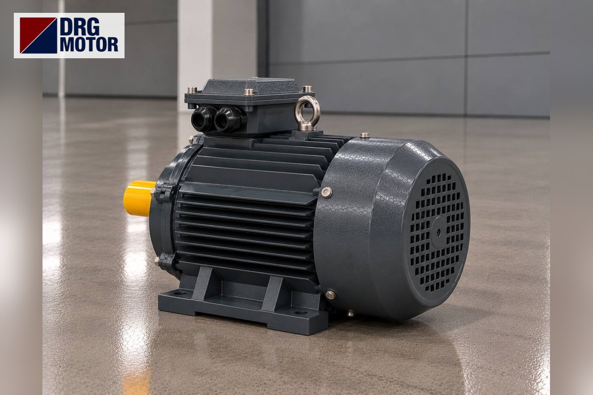
DRG Motor is an electric motor manufacturer, supplier and seller. The three-phase IEC motors below fall within the power range commonly used with direct-on-line start-stop circuits. Contactors, overload relays, buttons and indicator lamps are not sold by DRG; please contact your panel component supplier for those. More options are listed on the three-phase asynchronous electric motors page and in the online store.
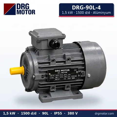
1.5 kW Three-Phase Motor 1500 rpm – DRG-90L-4 Aluminium
- 1.5 kW · 1500 rpm (4 poles)
- Aluminium frame · IEC 90L
- Mounting: B3 · B5 · B14 · B35
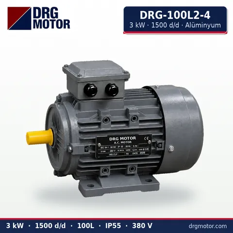
3 kW Three-Phase Motor 1500 rpm – DRG-100L2-4 Aluminium
- 3 kW · 1500 rpm (4 poles)
- Aluminium frame · IEC 100L
- Mounting: B3 · B5 · B14 · B35
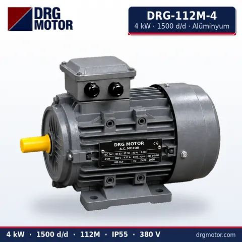
4 kW Three-Phase Motor 1500 rpm – DRG-112M-4 Aluminium
- 4 kW · 1500 rpm (4 poles)
- Aluminium frame · IEC 112M
- Mounting: B3 · B5 · B14 · B35
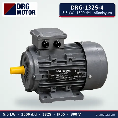
5.5 kW Three-Phase Motor 1500 rpm – DRG-132S-4 Aluminium
- 5.5 kW · 1500 rpm (4 poles)
- Aluminium frame · IEC 132S
- Mounting: B3 · B5 · B14 · B35
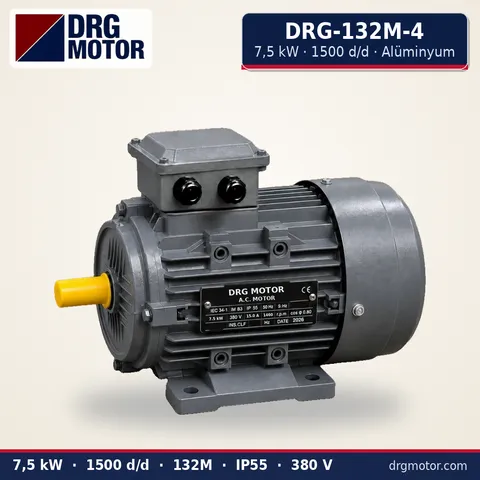
7.5 kW Three-Phase Motor 1500 rpm – DRG-132M-4 Aluminium
- 7.5 kW · 1500 rpm (4 poles)
- Aluminium frame · IEC 132M
- Mounting: B3 · B5 · B14 · B35
Click to see current prices for these motors and order nowSEE PRICES →
Frequently asked questions
Why is the holding contact wired in parallel with the start button?
Because its job is to take over from the start button. When the button is released, coil current keeps flowing through K1 13-14. Wired in series, the motor would never start.
Which contactor contact is used for self-holding?
A normally open auxiliary contact of the same contactor whose coil it feeds, shown as 13-14 here. A main contact is not used. Auxiliary numbering depends on the contactor or the add-on contact block.
Why is the stop button normally closed?
Coil current flows through the stop button. Pressing it, or a broken wire, opens the circuit and stops the motor. A normally open stop could not stop the motor if its wire broke.
Why does the motor not restart after a power cut?
When the voltage disappears, K1 drops out and 13-14 opens. When it returns, both paths to the coil are open, so the motor only starts on a new start command.
Is an overload relay needed when Q1 is used?
A motor protection breaker provides overload protection itself, so a separate relay is not normally added. Wire Q1’s auxiliary contact into the control circuit so that the control is also cut when Q1 trips.





