English
 Le français
 Türkçe





The difference between a thermal overload relay and a motor protection circuit breaker comes down to one sentence: a thermal overload relay only detects overload and does not interrupt the current itself — its auxiliary contact drops the contactor coil and lets the contactor stop the motor; a motor protection circuit breaker (often called a “thermal breaker” or “thermal-magnetic breaker” on site) combines overload and short-circuit protection in one housing, disconnects all three phases with its own power contacts and can be switched on and off by hand. A thermal relay always needs a contactor and a fuse upstream; a motor protection breaker can act as both switch and protection on a small motor.
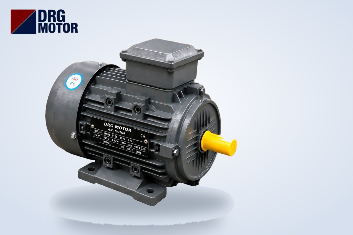
The overload setting comes from the same place on both devices: the rated current on the motor nameplate. For example, a 4 kW, 1500 rpm DRG-112M-4 motor draws 8.37 A at 380 V; whichever device you use, the setting is 8.37 A. The difference shows up in what happens during a short circuit, whether you can control the motor remotely with a push button, float switch or PLC, and how many parts you need in the panel. What happens inside a bimetal overload, its trip class and the step-by-step setting procedure are covered separately in our thermal overload relay guide; this article focuses only on the difference between the two devices and where each one should be chosen.
To set either device correctly you need the motor's nameplate current. Every one of the 120 models in our Buy Electric Motors Online store lists the current at 380, 400 and 415 V, the cos φ and the starting current ratio on its product page; all examples in this article were calculated from that data.
What does a thermal relay do, and what does a motor protection breaker do?
Thermal overload relay: the overload guard next to the contactor
A thermal overload relay is mounted under the contactor, on most models directly onto the contactor's output terminals. The motor's three phase currents pass through it; if the current exceeds the setting for a certain time, it opens its normally closed contact 95-96. If this contact is wired in series with the contactor coil in the control circuit, the contactor drops out and the motor stops. In other words, the part that opens the power circuit is the contactor, not the relay. The normally open contact 97-98 is used for a fault lamp, a horn or a PLC input.
A thermal relay is not designed to clear a short circuit. Short-circuit current destroys the cable, the contactor contacts and the relay itself long before the relay could heat up and trip. That is why a motor-rated fuse or a suitable circuit breaker is always installed upstream of a thermal relay.
Motor protection circuit breaker: switch and protection in one housing
A motor protection circuit breaker is installed at the head of the line. It contains an adjustable thermal trip element (overload) and a magnetic trip element (short circuit) designed to operate above the starting current. It trips with a delay on overload and without delay on a short circuit. It is switched on and off by hand with a rotary handle or push buttons, and when it trips it disconnects all three phases with its own contacts. Because it has no coil, it cannot be controlled remotely on its own: remote tripping needs an accessory (shunt trip) or a contactor downstream.
Thermal overload relay vs motor protection breaker: comparison table
| Feature | Thermal overload relay | Motor protection circuit breaker |
|---|---|---|
| Overload protection | Yes, adjustable current | Yes, adjustable current |
| Short-circuit protection | No; needs a fuse or circuit breaker upstream | Yes (magnetic trip) |
| What interrupts the current? | The contactor (the relay only opens a control contact) | The breaker's own power contacts |
| Manual on/off | No; only reset and test button | Yes; handle or buttons |
| Remote / automatic control | Possible together with a contactor | Not on its own; needs a contactor or accessory |
| Auxiliary contacts | 95-96 (NC) and 97-98 (NO) built in | Usually via an add-on auxiliary contact block |
| Position in the panel | Below the contactor | Head of the line, ahead of the contactor |
| Response to phase loss | Available on many models; check the device catalogue | Available on many models; check the device catalogue |
| After tripping | Reset (manual or automatic, selectable) | Handle is switched on again |
| Typical use | Contactor circuits with remote control, star-delta | Manually operated small and medium motors; compact starters with a contactor |
The decisive row in the table is “what interrupts the current?”. If the relay's 95-96 contact is not wired into the control circuit, the motor keeps running even after the relay trips; there is an overload relay in the panel but no protection. This wiring mistake cannot happen with a motor protection breaker, because tripping takes place directly at the power contacts.
How does the panel layout change?
Three layouts are seen on site for the same motor. The choice depends on how the motor is started and stopped:
| Layout | Power circuit sequence | Short circuit | Overload | Remote control |
|---|---|---|---|---|
| A – Classic | Supply → fuse → contactor → thermal relay → motor | Fuse | Thermal relay | Yes |
| B – Single device | Supply → motor protection breaker → motor | Motor protection breaker | Motor protection breaker | No |
| C – Compact | Supply → motor protection breaker → contactor → motor | Motor protection breaker | Motor protection breaker | Yes (contactor) |
In layout A the control circuit is built in this order: control fuse → stop button (NC) → start button (NO) with the contactor's hold-in contact in parallel → relay contact 95-96 → contactor coil. In layout C no thermal relay is needed; the breaker's auxiliary contact is wired in series in the control circuit so that the contactor also drops out when the breaker trips and the motor does not restart by itself when voltage returns.
When to use a thermal relay and when a motor protection breaker?
Motor power alone is not decisive; what matters is how the motor is controlled and the setting range of the device family chosen. The decision table below summarises typical situations:
| Situation | Suitable layout | Why |
|---|---|---|
| Manually switched machine, grinder, mixer | B | One device is both switch and protection; no control circuit needed |
| Pump or fan run by a float switch, pressure switch, timer or PLC | A or C | Automatic switching needs a coil-operated device, i.e. a contactor |
| Star-delta starting | A or C | The three contactors are already there; protection is done either at phase current with a relay or at the line head with a breaker |
| Motor that starts and stops very often during the day | C | Leaving the switching to the contactor spares the breaker mechanism |
| Large motor with no motor protection breaker in a suitable setting range | A (or an electronic protection relay) | At high power, protection is usually built with fuses or a moulded-case breaker + contactor + relay |
In star-delta circuits the current to be set depends on where the device sits; for starting options see our Motor Starting Methods (Star-Delta) tool. The next section shows it in numbers.
Setting examples for three motors
The values below are taken from DRG catalogue data. Starting current is the nameplate current multiplied by the starting current ratio (Is/In); the star-delta column shows the case where the relay sits after the main contactor, i.e. in the phase winding current (In ÷ √3).
| Model | Nameplate voltage | kW | Rated current 400 V | Rated current 380 V = DOL setting | Phase-current setting in star-delta (In/√3) | Starting current at 380 V (Is/In × In) |
|---|---|---|---|---|---|---|
| DRG-90L-4 | 230/400 V, star at 380 V | 1.5 | 3.3 A | 3.47 A | not applicable | 7.0 × 3.47 ≈ 24.3 A |
| DRG-112M-4 | 400/690 V, delta at 380 V | 4 | 7.95 A | 8.37 A | 8.37 ÷ 1.732 ≈ 4.83 A | 7.8 × 8.37 ≈ 65.3 A |
| DRG-180L-4 | 400/690 V, delta at 380 V | 22 | 39.7 A | 41.8 A | 41.8 ÷ 1.732 ≈ 24.13 A | 7.8 × 41.8 ≈ 326.0 A |
Four conclusions from the table
- Set for the actual supply voltage: if your plant measures 400 V, the setting for the 4 kW motor is not 8.37 A but 7.95 A, the 400 V current on the nameplate.
- Star-delta only on a 400/690 V nameplate: DRG-90L-4 has a 230/400 V nameplate and is connected in star at 380 V; it is not suitable for star-delta starting, so the table says “not applicable”.
- The device position changes the setting: on the 22 kW motor a thermal relay located after the main contactor, on the phase winding, is set to 24.13 A. If protection in the same circuit is provided by a motor protection breaker at the head of the line, the breaker sees the line current and is set to 41.8 A. Mixing the two either leaves the motor unprotected or causes nuisance trips on every start.
- The magnetic trip must carry the starting current: the 4 kW motor briefly draws about 65.3 A when starting. If the breaker's short-circuit threshold is not chosen to carry this peak, the motor trips the breaker on every start; that is a selection error, not a motor fault.
When selecting, the device's setting scale should cover the rated current comfortably; prefer a size where the rated current falls inside the scale rather than a device whose setting lands at the very end of its scale. Example values for contactor, overload and fuse by motor power are available in our Overload, Fuse and Contactor Selection tool.
Use with fuses and the most common mix-ups
Why is a fuse mandatory ahead of a thermal relay?
Because a thermal relay cannot clear short-circuit current, a motor-rated (time-delay) fuse or a circuit breaker suitable for motor protection must be installed ahead of it in the power circuit. The fuse is chosen so that it carries the motor's starting current without blowing but protects the cable in a short circuit; in other words, the fuse is checked not only against the motor but also against the cross-section of the cable installed.
Does a motor protection breaker need a fuse upstream?
In most cases no, because the breaker has its own short-circuit protection. The exception is when the breaker's breaking capacity (the Icu/Ics value in the catalogue) is lower than the prospective short-circuit current at its location. This can happen in main panels close to a large transformer; a back-up fuse matching the manufacturer's table is then installed ahead of the breaker. This calculation depends on the plant's short-circuit level and should be verified by an electrical engineer.
Five points most often confused on site
- Asking for a “thermal breaker” and buying a thermal relay: in a panel without a contactor there is neither a place to mount the relay nor a circuit for it to open.
- Fitting a thermal relay but not wiring contact 95-96 into the control circuit: the relay trips, the motor keeps running.
- Setting both a motor protection breaker and a thermal relay in the same circuit to the same current: double overload protection gains nothing and makes it unclear which device tripped.
- Choosing line current (In) or phase current (In/√3) in star-delta without checking where the device sits.
- Selecting a motor protection breaker without considering the starting current and blaming the motor for tripping on every start.
Is the device in the panel a thermal relay or a motor protection breaker? Checklist
- Does the device have a rotary handle or “I / O” push buttons? If so, it is a motor protection breaker.
- Is the device plugged directly under a contactor? If so, it is most likely a thermal relay.
- Are there auxiliary terminals numbered 95-96 and 97-98 on the housing? That is the sign of a thermal relay.
- Is there a separate fuse or circuit breaker ahead of it? It is mandatory for a thermal relay.
- Is the value on the setting scale the same as the nameplate current for your supply voltage?
- In a star-delta circuit, is the device on the line or after the main contactor? Was the setting checked as In or In/√3 accordingly?
- In a relay circuit, is contact 95-96 in series between the stop button and the contactor coil?
- Is the breaking capacity of the motor protection breaker suitable for the prospective short-circuit current in the panel?
- Is the relay's reset mode set to manual? Automatic reset can make the motor restart by itself.
Motors used in the setting examples
- DRG-90L-4 – 1.5 kW – 4-pole (1500 rpm) – aluminium – 230/400 V nameplate
- DRG-112M-4 – 4 kW – 4-pole (1500 rpm) – cast iron – 400/690 V nameplate
- DRG-160L-4 – 15 kW – 4-pole (1500 rpm) – cast iron – 400/690 V nameplate
- DRG-180L-4 – 22 kW – 4-pole (1500 rpm) – cast iron – 400/690 V nameplate
Click to see current prices and order these motors nowSEE PRICES →
Frequently Asked Questions
Is a thermal breaker the same as a thermal overload relay?
No. What is called a “thermal breaker” on site is usually a motor protection circuit breaker: it protects against overload and short circuit, interrupts the current with its own contacts and is switched by hand. A thermal overload relay only detects overload and stops the motor through a contactor.
Can a motor protection breaker replace a contactor?
If the motor is switched by hand, yes, it is enough on its own. If the motor runs automatically from a float switch, pressure switch, timer or PLC, or starts and stops very often during the day, a contactor is added downstream.
Does a motor protection breaker need a fuse in front of it?
Usually not; the breaker has its own short-circuit protection. If its breaking capacity is lower than the short-circuit current at its location, a back-up fuse matching the manufacturer's table is installed ahead of it. If a thermal relay is used, a fuse is always required.
What current should a motor protection breaker be set to for a 4 kW motor?
For the 4 kW, 1500 rpm DRG-112M-4 motor the setting is 8.37 A on a 380 V supply and 7.95 A on a 400 V supply. The breaker's setting range must include this value and its short-circuit threshold must carry the starting current of about 65.3 A.
If you are not sure which motor current to set the protective device to, send the motor code or a photo of the nameplate to [email protected] or call +90 (542) 666 11 11; other channels are on our contact page. The list of 120 models with nameplate currents: Buy Electric Motors Online.