 English
 Le français
 Türkçe




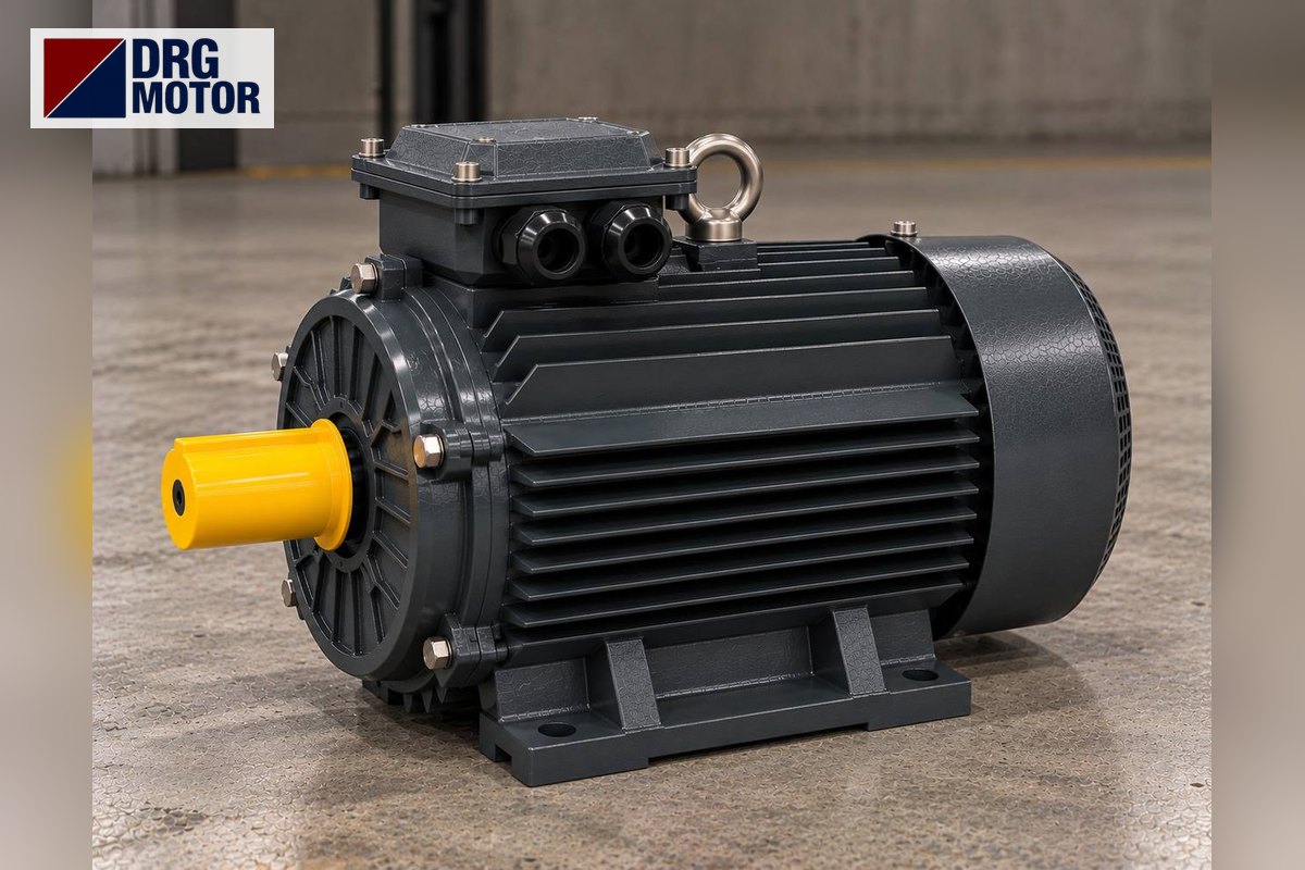

In pressure-switch motor control, the normally closed (NC) contact of the pressure switch is wired in series with the coil of contactor K1. While the pressure is below the lower setting the contact is closed, K1 picks up and the motor runs; when the upper setting is reached the contact opens, K1 drops out and the motor stops. The three-phase motor current never passes through the switch: the K1 main contacts switch the motor.
Safety notice: This content is for technical information only. Wiring, measurement and commissioning must be carried out by qualified electrical personnel, following lock-out and verification of de-energised state, and in line with the motor and device manufacturer's documentation.
This article covers the power and control circuits, the cut-in/cut-out pressure curve, a compressor and a booster pump example, the short-cycling problem and an optional hand–off–auto selector. Pressure values in the graphs are representative; terminal names vary by device and the device's own wiring diagram prevails.
Where does the pressure switch sit in the circuit?
The most common field mistake is trying to put the pressure switch in the motor's power line. On a three-phase motor its place is the control circuit. The power side is built in the usual order: F1 fuses (or a motor protection breaker), K1 main contacts 1-2 / 3-4 / 5-6, F2 overload relay and the motor. The pressure switch is not in that path; it only switches the current of the K1 coil. Its contact is therefore chosen for the coil current and the control voltage, not for the motor current.
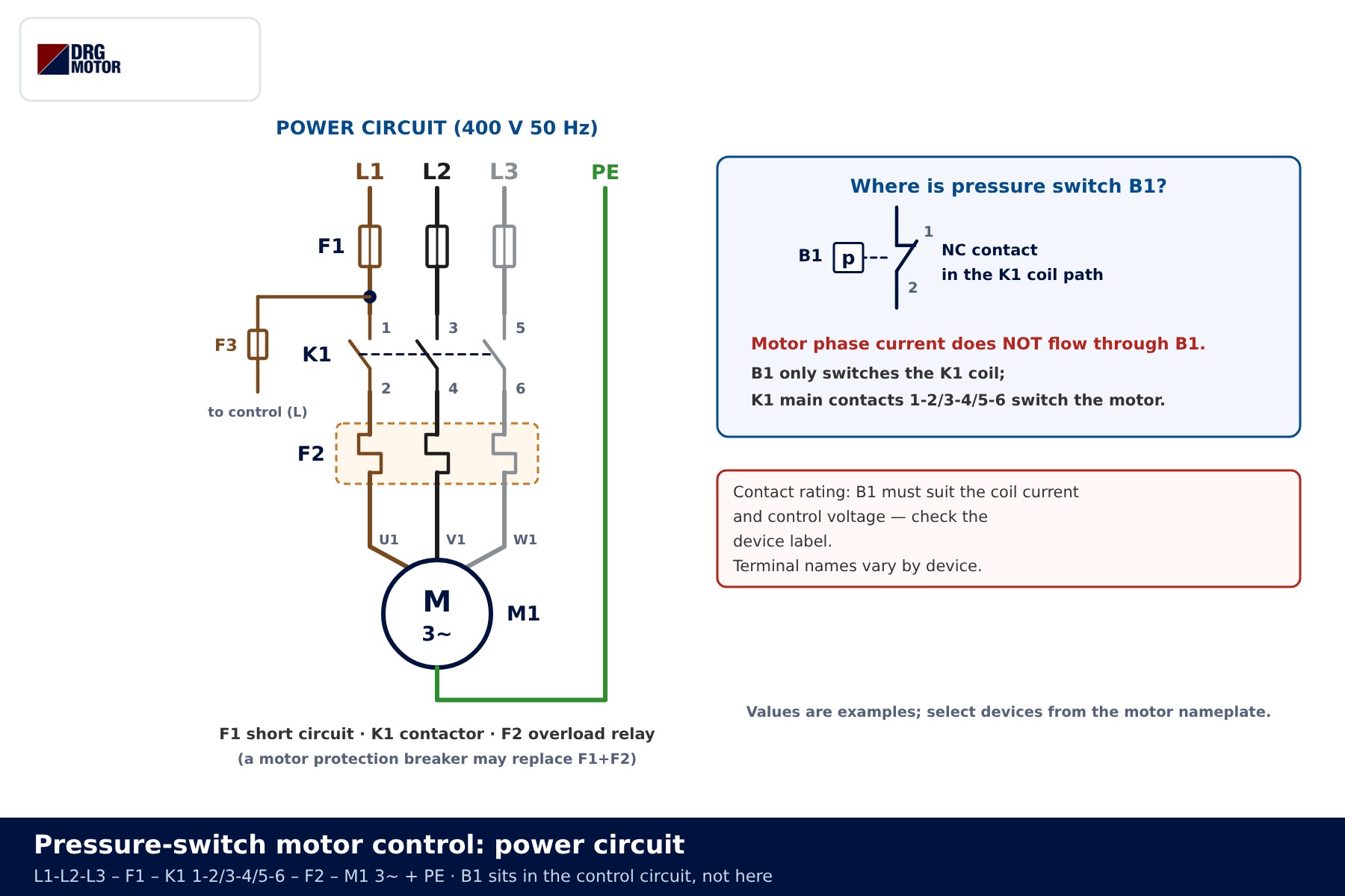
| Component | Terminals | Function |
|---|---|---|
| F1 fuses | one per phase | Short-circuit protection of the power circuit |
| K1 contactor | A1-A2 coil, 1…6 main, 13-14 auxiliary | Connects the motor to the supply; its coil is driven by the pressure switch |
| F2 overload relay | main poles + 95-96 NC, 97-98 NO | Opens the control circuit on overload, lights the fault lamp |
| F3 control fuse | single pole | Protects the control wiring |
| Run switch (0-1) | 13-14 NO | Takes the system out of service by hand |
| B1 pressure switch | 1-2 NC (example) | Closes at the lower pressure, opens at the upper pressure |
| H1 / H2 lamps | K1 13-14 / F2 97-98 | Running and overload indication |
| M1 motor | U1 V1 W1 + PE | Three-phase motor driving the pump or compressor |
Protective devices are sized from the rated current on the motor nameplate; use the overload, fuse and contactor selection tool for a first choice and the motor current chart for rated currents. The difference between an overload relay and a motor protection breaker is explained in thermal overload relay vs motor protection breaker.
Control circuit: why the NC contact sits in the coil path
The control circuit is a single ladder rung. The top rail carries L (230 V AC in the example); current flows through the F3 control fuse, the F2 95-96 contact, the run switch and the NC contact of B1 to terminal A1 of the K1 coil, while A2 returns to N. Unlike a start-stop circuit there is no self-holding contact, because the pressure switch itself keeps the motor on: as long as the contact stays closed, the coil stays energised.
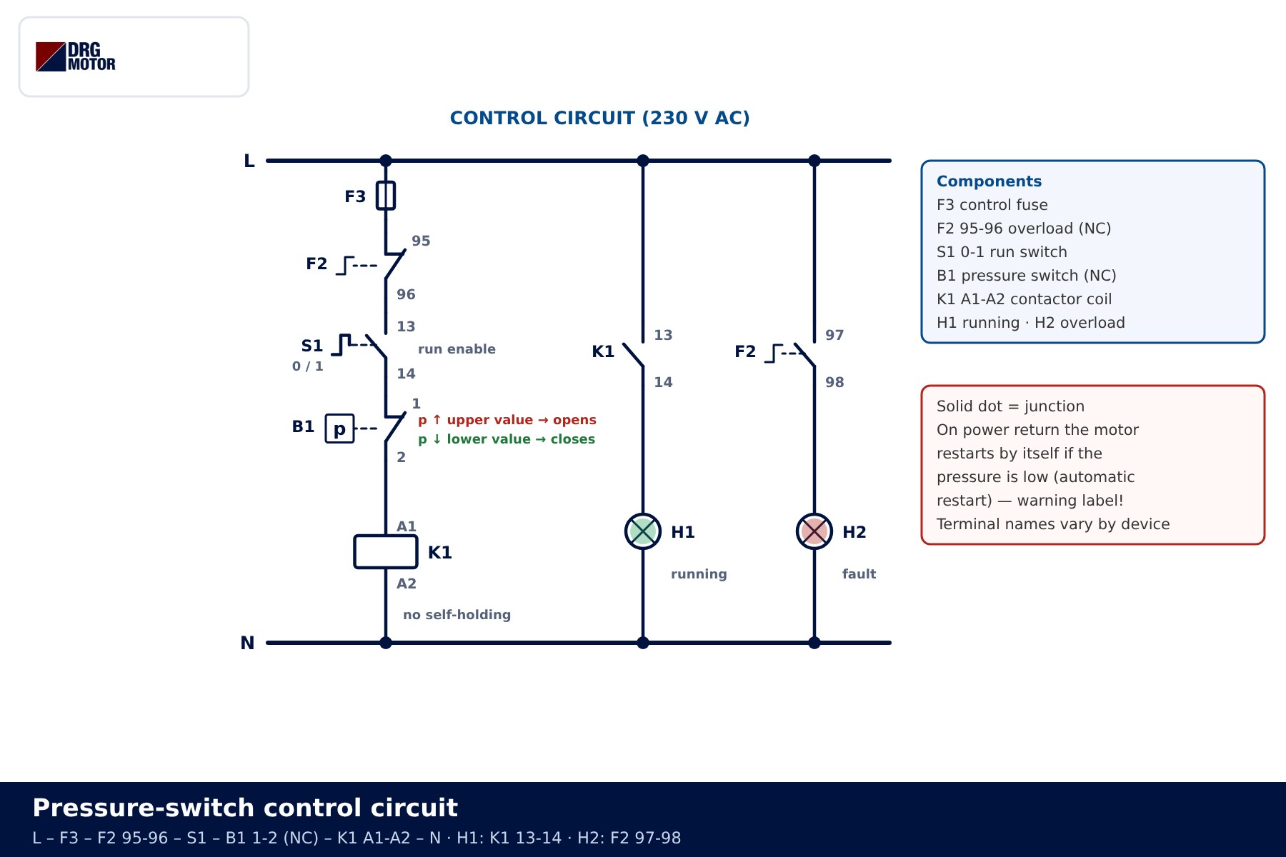
The reason for using an NC contact is simple. The motor must run when the pressure is low, and that is exactly when the switch is closed. As pressure rises, the diaphragm or bellows inside the switch pushes against a spring and the contact opens at the upper setting. The contact block may have several terminals; check on the device's own diagram which pair is "closed at low pressure".
Having no self-holding has one important consequence: when power returns after an outage and the pressure is low, the motor starts without anyone touching anything. That is the intended behaviour, but it can surprise a maintenance technician. Put an "automatic restart" warning on the panel door and lock out the supply before any work.
📄 Download Wiring Diagram PDF A4 printable PDF of the diagrams and tables (no sign-up)
Cut-in and cut-out pressure: reading the differential (Δp)
A pressure switch has two thresholds. The lower one (cut-in) is where the motor starts, the upper one (cut-out) is where it stops. The gap between them is called the differential, Δp. Between the two thresholds the switch keeps its last state: closed while filling, open while the system is being drawn down. Without this hysteresis the motor would chatter on and off around a single point.
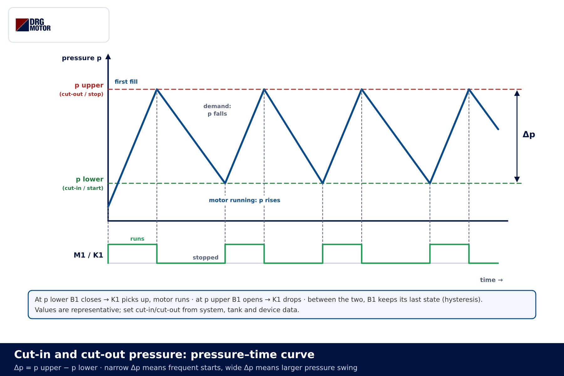
In the graph the blue curve is the tank pressure and the green strip underneath is the motor state. While the motor runs the pressure rises; at cut-out the motor stops and demand pulls the pressure down; at cut-in the motor starts again. A narrow Δp makes the tank work with a small volume and the motor starts often; a wide Δp cuts the number of starts but increases pressure swings at the outlets. Threshold values depend on the system demand, tank volume and the switch's adjustment range, so no setting value is given here.
Click to see current electric motor prices and order nowSEE PRICES →
Step-by-step operation and state table
- First power-up: the system is empty and the pressure is below cut-in. B1 is closed; with the run switch at 1, K1 picks up and the motor starts.
- Filling: pressure rises. B1 does not open when cut-in is passed; the motor runs up to cut-out.
- Cut-out reached: B1 opens, the K1 coil is de-energised and the motor stops. H1 goes out.
- Demand: pressure falls. B1 stays open down to cut-in.
- Cut-in reached: B1 closes and the motor restarts. The cycle repeats.
- Overload trip: F2 95-96 opens, the motor stops regardless of pressure and H2 lights. After reset, the motor restarts by itself if the pressure is low.
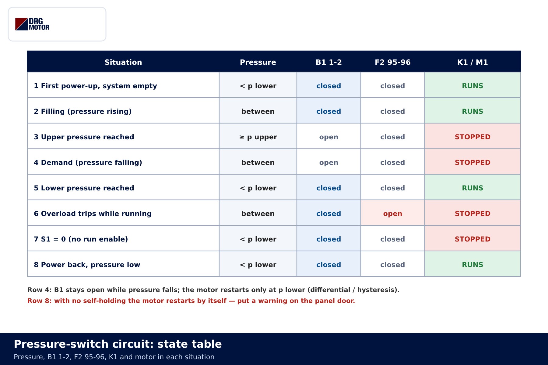
| Situation | B1 1-2 | K1 coil | Motor |
|---|---|---|---|
| Pressure below cut-in | closed | energised | runs |
| Between thresholds, filling | closed | energised | runs |
| Cut-out reached | open | de-energised | stopped |
| Between thresholds, demand | open | de-energised | stopped |
| Overload tripped | closed | de-energised | stopped, H2 on |
| Power back, pressure low | closed | energised | restarts by itself |
Application examples: compressor and booster pump
Compressor: air receiver
On a piston compressor the pressure switch is usually mounted on the air receiver and senses receiver pressure. Air from the compressor pump passes a check valve into the receiver; the check valve stops the stored air flowing back when the motor stops. Many compressors have a small unloader valve working with the switch: when the motor stops it vents the line between the pump and the check valve, so on the next start the motor accelerates against an empty line instead of full pressure.
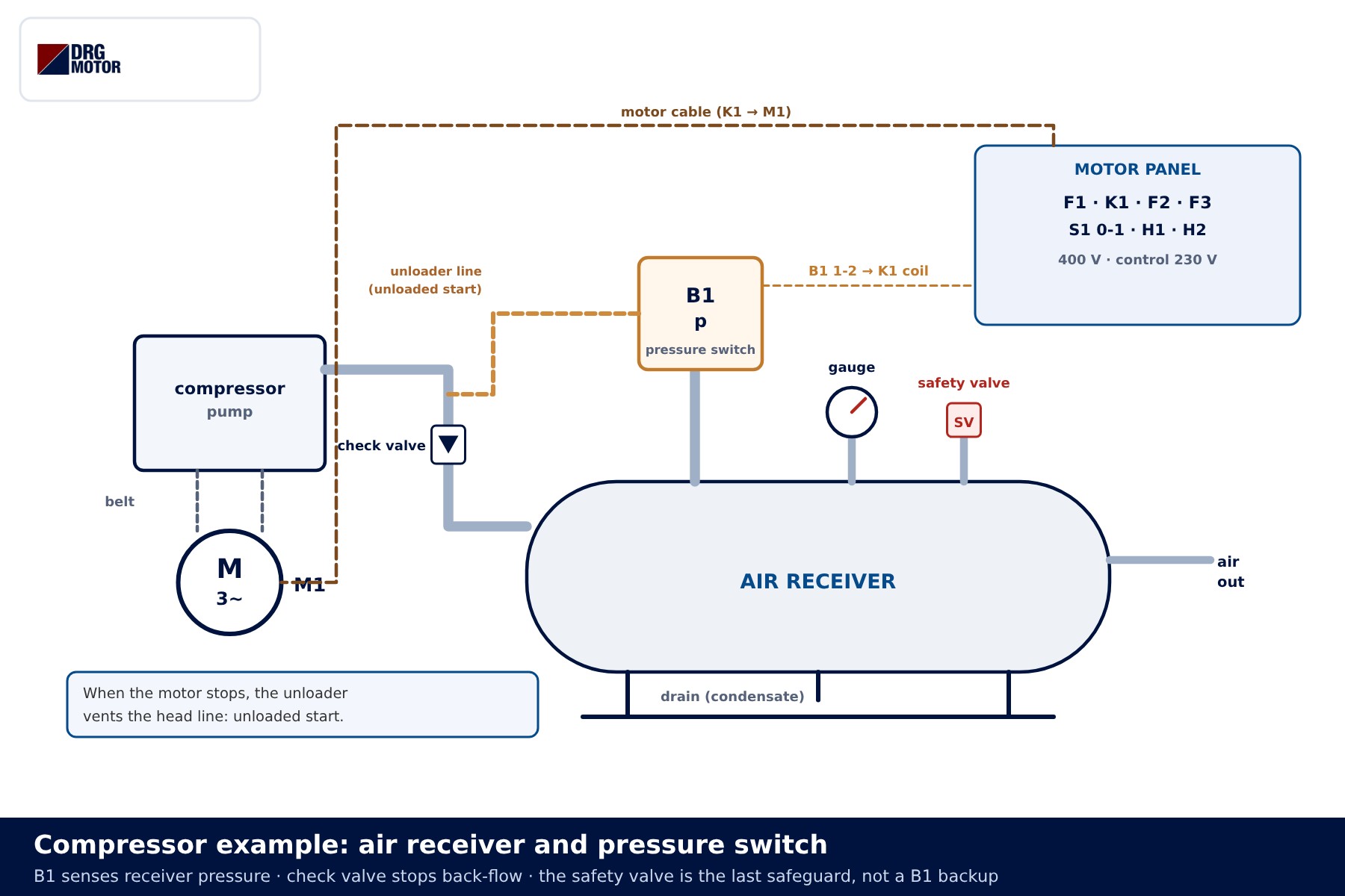
If the unloader fails, the motor tries to start against a pressurised line every time; acceleration takes longer, current stays high and the overload relay may trip. The safety valve on the receiver is not a backup for the pressure switch; it is the last safeguard if the switch or contactor fails, and it must be checked regularly.
Booster pump: expansion tank
In a booster set the pump draws from the tank, pushes through a check valve into the manifold, and the manifold carries a membrane expansion tank, the pressure switch and a gauge. The expansion tank holds enough water to cover demand for a while after the motor stops. The pre-charge on its air side is set with the pump off and the water side empty, according to the tank and switch data.
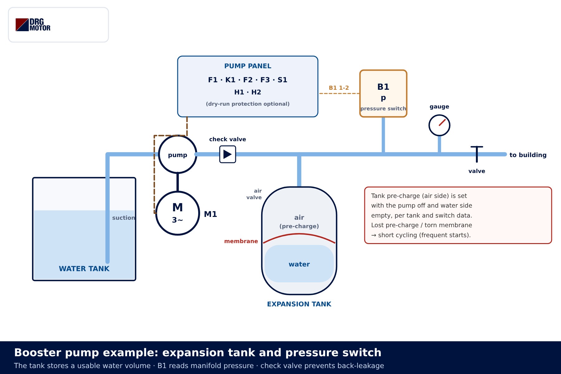
If the pre-charge is lost or the membrane tears, the tank fills with water, its usable volume drops to almost nothing and the motor starts every time a tap opens. How this wears the motor out is covered in why a booster pump motor burns out. If the pump also needs dry-run protection, a low-water device can be added in series in the same control path as another NC contact.
Short cycling: frequent starts
When the motor in a pressure-switch system keeps starting and stopping at short intervals, this is called short cycling. Every start draws several times the rated current; the winding heats up and the contactor contacts wear. How many starts per hour a motor can take depends on the motor and the load: check the nameplate or the manufacturer's data rather than adjusting to a guessed number.
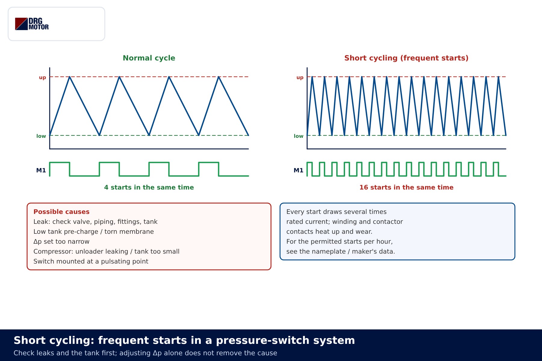
The cause is usually on the hydraulic or pneumatic side rather than the electrical side: a leaking check valve, a leak in the piping, an expansion tank that has lost its pre-charge, an unloader that does not close, or a Δp set too narrow. The checks to make before buying a new motor are listed in booster pump motor starts too often: what to check first.
Optional: hand–off–auto selector
A three-position selector lets you run the motor independently of the pressure switch during service or a fault. In AUTO the coil is fed through selector contact 23-24 and B1; in HAND contact 13-14 bypasses B1; in OFF both paths are open. F3 and F2 95-96 stay ahead of both paths, so the overload relay stops the motor in every position.
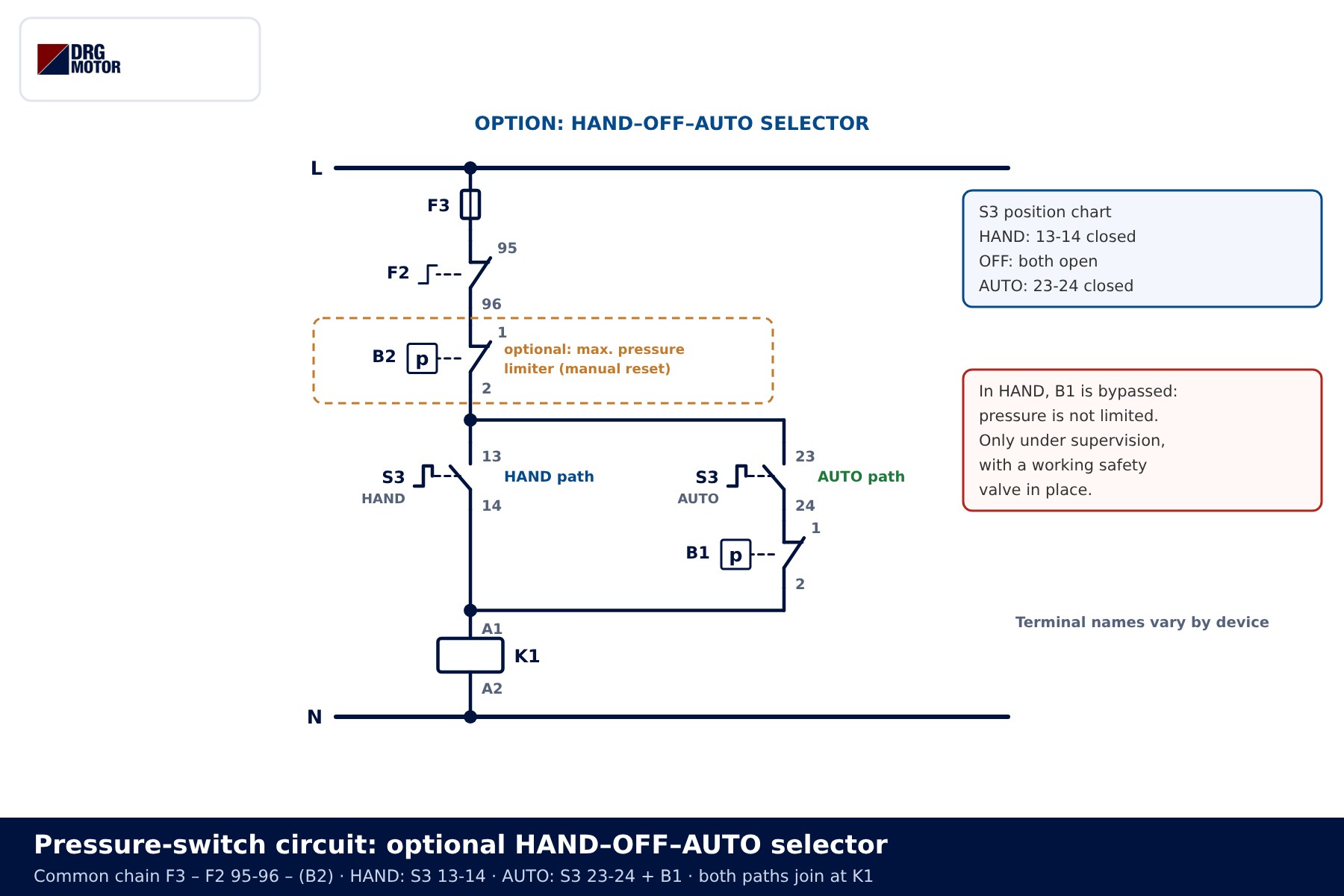
In HAND the pressure is not limited. Use this position only under supervision and with a working safety valve; where the installation requires it, a separate manually reset maximum-pressure limiter (B2 in the diagram) goes into the common chain. Reading the selector together with the ladder logic in the star-delta control circuit article makes the wiring easier to follow.
Common wiring mistakes and selection examples
Common wiring mistakes
| Symptom | Likely cause |
|---|---|
| Motor starts when pressure rises and stops when it falls | The NO terminal of the switch was used; change to the NC terminal |
| Switch contact burns or welds quickly | Switch wired into the motor power line, or contact rating unsuitable for the coil |
| Motor does not stop at cut-out | Blocked pressure connection, welded contact, or selector left in HAND |
| Motor starts unexpectedly when power returns | No self-holding; normal if pressure is low — fit a warning label |
| Contactor stays in although the overload has tripped | 97-98 used instead of 95-96 |
| Motor starts far too often | Leak, tank pre-charge, unloader or narrow Δp; check the fluid side first |
If the overload relay trips repeatedly, see why an electric motor trips the overload relay; how to set it from the nameplate is explained in what a thermal overload relay does.
Motor and cable selection
- Booster pump, 2.2 kW, 3000 rpm, 230/400 V Δ/Y motor on a 400 V supply: the motor is connected in star. Contactor and overload relay are chosen from the nameplate current; the frame and bearing arrangement must suit the pump coupling.
- Compressor, 4 kW, 1500 rpm, 400/690 V Δ/Y motor on a 400 V supply: the motor is connected in delta. On a belt-driven compressor the pulley ratio starts from the motor speed; for the number of starts the nameplate applies.
- Cable: the cross-section depends on run length, installation method and the protective device. The motor cable size calculator gives a starting value.
📄 Download Wiring Diagram PDF A4 printable PDF of the diagrams and tables (no sign-up)
Send a photo of your current motor nameplate and we will find the suitable DRG model together.Send on WhatsApp
DRG motors for pressure-switch pumps and compressors
DRG Motor is an electric motor manufacturer, supplier and seller. The three-phase IEC motors below are in the power range typically found on booster sets and compressors. Pressure switches, contactors, overload relays and selectors are not sold by DRG; source them from your panel components supplier or the device manufacturer. Other ratings and speeds are listed under three-phase asynchronous electric motors and in the online store.
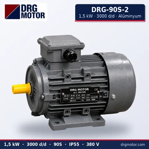
1.5 kW Three-Phase Motor 3000 rpm – DRG-90S-2 Aluminium
- 1.5 kW · 3000 rpm (2 poles)
- Aluminium frame · IEC 90S
- Mounting: B3 · B5 · B14 · B35
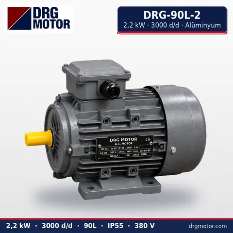
2.2 kW Three-Phase Motor 3000 rpm – DRG-90L-2 Aluminium
- 2.2 kW · 3000 rpm (2 poles)
- Aluminium frame · IEC 90L
- Mounting: B3 · B5 · B14 · B35
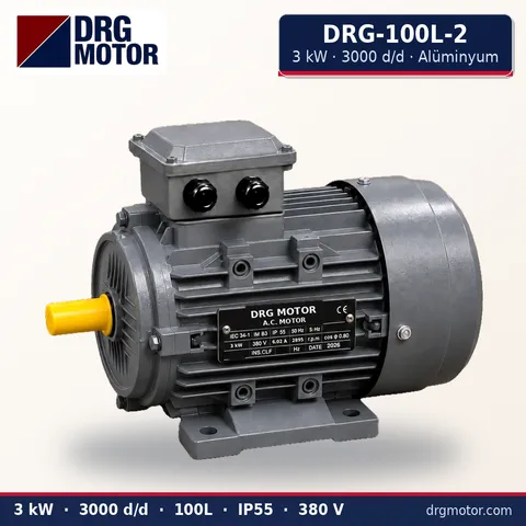
3 kW Three-Phase Motor 3000 rpm – DRG-100L-2 Aluminium
- 3 kW · 3000 rpm (2 poles)
- Aluminium frame · IEC 100L
- Mounting: B3 · B5 · B14 · B35
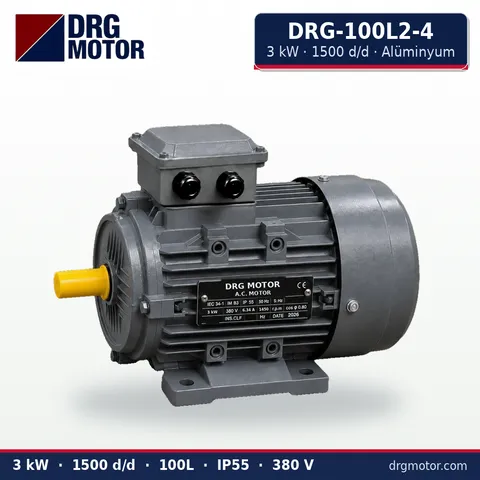
3 kW Three-Phase Motor 1500 rpm – DRG-100L2-4 Aluminium
- 3 kW · 1500 rpm (4 poles)
- Aluminium frame · IEC 100L
- Mounting: B3 · B5 · B14 · B35
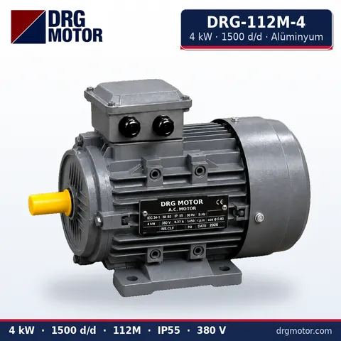
4 kW Three-Phase Motor 1500 rpm – DRG-112M-4 Aluminium
- 4 kW · 1500 rpm (4 poles)
- Aluminium frame · IEC 112M
- Mounting: B3 · B5 · B14 · B35
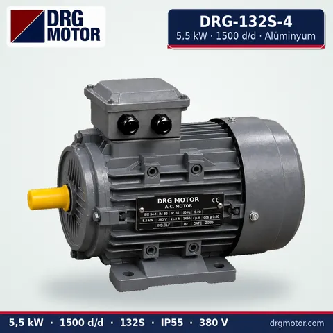
5.5 kW Three-Phase Motor 1500 rpm – DRG-132S-4 Aluminium
- 5.5 kW · 1500 rpm (4 poles)
- Aluminium frame · IEC 132S
- Mounting: B3 · B5 · B14 · B35
Click to see current prices for these motors and order nowSEE PRICES →
Frequently asked questions
Can a pressure switch be connected directly to a three-phase motor?
On a three-phase motor the switch contact is not used to carry motor current. It goes into the coil path of contactor K1, and the contactor's main contacts switch the motor. Check the device label to confirm the contact suits the coil current and control voltage.
Which pressure switch contact should be used?
The contact that is closed at low pressure and opens at the upper setting, i.e. the NC contact. Terminal numbers differ between devices; confirm the right pair on the switch's own diagram.
Why does the cut-in/cut-out differential matter?
It decides how much volume the tank delivers between one stop and the next start. A narrow differential means frequent starts; a wide one means larger pressure swings. It is chosen to suit the system demand and the tank volume.
Why does the motor restart by itself after a power cut?
There is no self-holding in a pressure-switch circuit. If the pressure is below cut-in, the switch is closed and K1 picks up as soon as voltage returns. Lock out the supply before maintenance and put a warning on the panel.
How many times per hour can the motor start?
It depends on the motor rating, the load inertia and cooling conditions. Refer to the nameplate or the manufacturer's data; if you see frequent starts, check leaks, the tank and the Δp setting first.





