 English
 Le français
 Türkçe

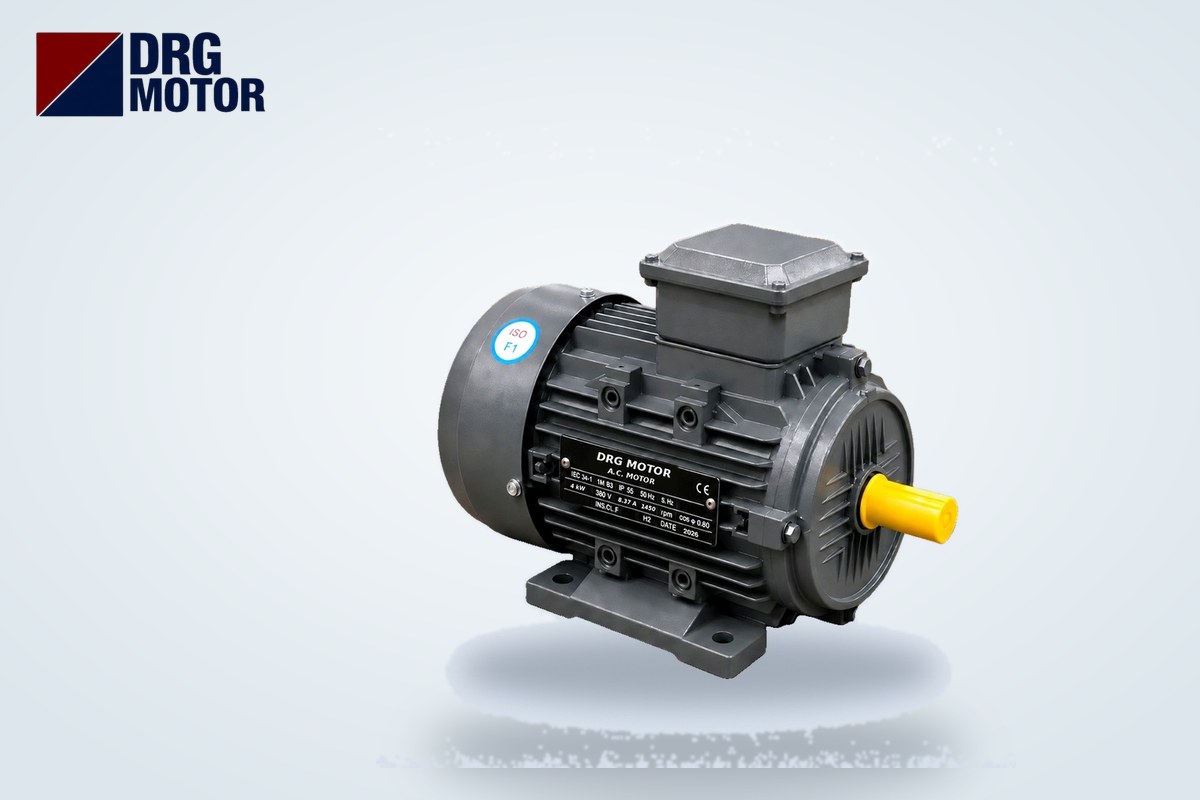

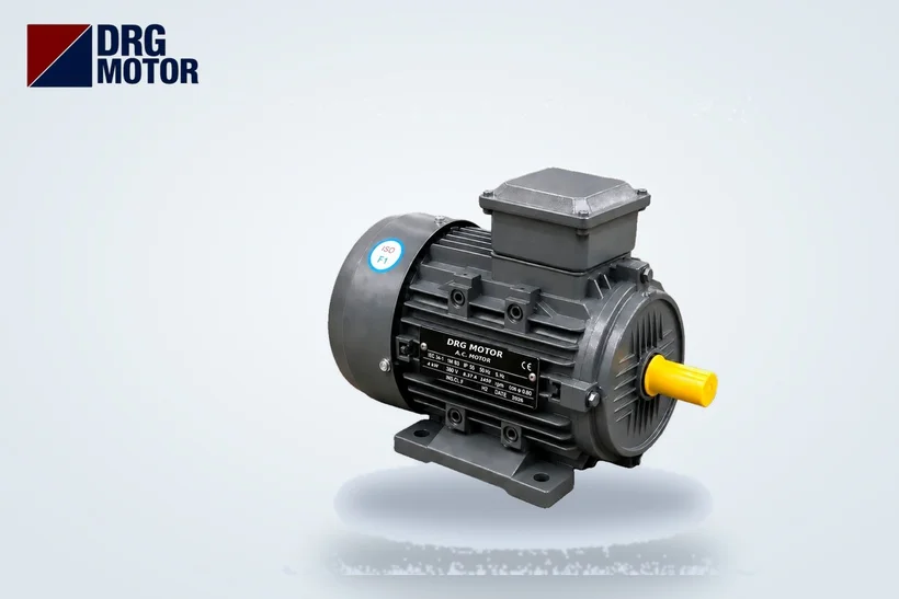
A thermal overload relay is a protective device that detects when a motor draws more than its rated current for a prolonged time (overload) or loses a phase, and stops the motor before the windings overheat by opening the contactor coil circuit. The correct setting is the nameplate current (In) for a direct-on-line motor, and the phase current, i.e. In/√3, for a star-delta started motor. For example, a 4 kW, 1500 rpm motor (DRG-112M-4) draws 8.37 A at 380 V; the overload is set to 8.37 A for direct-on-line starting and to about 4.83 A for star-delta.
A thermal overload relay does not protect against short circuits; that is the job of the fuse or the magnetic trip of the circuit breaker. The overload relay deals with slowly developing danger: a jammed belt, a gearbox low on oil, low voltage or a lost phase making the motor draw excess current for minutes. In this article we explain how to set it, what the trip class means and the most common field mistakes, using real motor data. You can find the motors in the examples and other models by kW and speed on our Buy Electric Motors Online page.
We covered the differences between general overload protection methods (thermal relay, motor protection circuit breaker, electronic relay, winding sensors) in Methods of Protecting an Electric Motor Against Overload; here we focus on the thermal overload relay itself and its setting.
How does a thermal overload relay work?
Bimetallic (thermal) overload relay
In a classic overload relay, the current of each phase heats a strip made of two different metals. As current rises the strip bends, and when the bending reaches a certain point the mechanism opens the auxiliary contact (usually 95-96, normally closed). Because this contact is wired in series with the contactor coil, the contactor drops out and the motor stops. Since heating takes time, the relay does not react immediately to the short starting current; the larger the current, the faster it trips. This is called an inverse-time characteristic.
Electronic overload relay
Electronic relays measure current with current transformers and model the motor's heating in software. Their setting range is usually wider, the trip class can be selected and they are less affected by ambient temperature. Some models include additional protection for phase imbalance and earth leakage.
Phase loss protection
When one of the three phases is lost, the motor tries to keep running on the remaining two and the current in those phases rises noticeably. Phase-failure-sensitive overload relays detect that the three bimetals do not bend equally (differential mechanism) and trip earlier than the normal overload curve. One of the most common reasons a motor burns out on a single phase is an overload relay without this feature or with a wrong setting.
How to set an overload relay: direct-on-line and star-delta starting
First read the rated current from the nameplate column that corresponds to the supply voltage. The nameplate current at 380 V differs from that at 400 V; use the one closest to your supply.
- Direct-on-line starting: The relay is in the main line and sees the line current. Setting = In.
- Star-delta starting: The relay is usually at the output of the main contactor, i.e. in the winding phase, and sees the phase current. Setting = In / √3 ≈ In × 0.58.
- If the relay is connected on the supply side (before the main contactor, in the line current), the setting is again In. Confirm the relay position from the panel diagram.
Star-delta starting applies only to motors that run in delta on a 380 V supply, i.e. those with a 400/690 V nameplate. Small motors rated 230/400 V run in star at 380 V, so star-delta is not used on them and the relay is set directly to In.
| Model | Power / speed | Connection at 380 V | In 380 V | In 400 V | DOL setting (380 V) | Star-delta setting (380 V, In/√3) |
|---|---|---|---|---|---|---|
| DRG-90L-4 | 1.5 kW / 1500 rpm | Y (star) | 3.47 A | 3.3 A | 3.47 A | Not applicable |
| DRG-112M-4 | 4 kW / 1500 rpm | Δ (delta) | 8.37 A | 7.95 A | 8.37 A | ≈ 4.83 A |
| DRG-132M-4 | 7.5 kW / 1500 rpm | Δ (delta) | 15 A | 14.3 A | 15 A | ≈ 8.66 A |
| DRG-160M-4 | 11 kW / 1500 rpm | Δ (delta) | 21.5 A | 20.4 A | 21.5 A | ≈ 12.41 A |
| DRG-200L-4 | 30 kW / 1500 rpm | Δ (delta) | 56.6 A | 53.8 A | 56.6 A | ≈ 32.68 A |
The setting range of the relay you choose should cover this value somewhere in the middle. If the setting falls at the very end of the range, choosing the relay with the next range up or down leaves adjustment margin for a future motor change or a different voltage. For contactor and relay ranges you can use our overload relay, fuse and contactor selection tool.
Should the setting be lowered if the motor is not fully loaded?
Some maintenance staff measure the actual running current with a clamp meter and set the relay slightly above it. This may look like better protection, but it can cause nuisance trips when the load fluctuates or in summer heat. The general practice is to set the nameplate current; if more sensitive protection is needed, the reason and value should be stated in the machine documentation. Setting above the nameplate current effectively disables the protection.
What is trip class? Class 10 vs Class 20
The trip class states the maximum time in seconds within which the relay, starting from cold, trips at about 7.2 times the set current. For a Class 10 relay this time is at most 10 seconds, for Class 20 at most 20 seconds and for Class 30 at most 30 seconds. The higher the class number, the longer the relay tolerates the starting current.
Why does this matter? A direct-on-line motor draws several times its rated current at start-up. For DRG-160M-4 the catalogue starting current ratio is Is/In = 7.7; at 380 V that means 21.5 × 7.7 ≈ 165.6 A. With a light load (fan, empty belt) the motor reaches speed in a few seconds and a Class 10 relay easily covers this time. With high-inertia loads (large fan impeller, loaded mill, crusher, flywheel press) start-up takes longer; a Class 10 relay may trip before the motor reaches speed. The wrong solution is to set the relay far above In. The right solution is to choose a relay of the appropriate class (Class 20 or 30) or to change the starting method.
Where start-up is long, PTC thermistors fitted in the motor winding add another safety layer to the overload relay; see Motor Temperature Protection with Thermistor (PTC) and PT100. You can compare how starting methods affect starting current on our star-delta and motor starting methods page.
Testing and resetting an overload relay
Overload relays often stay in the panel untouched for years. In periodic maintenance, these steps provide an adequate check:
- Test button: Pressing TEST while the motor runs should open contact 95-96, drop out the contactor and stop the motor. If it does not stop, the control diagram or contact wiring is wrong.
- Status indicator: Check the indicator position after a trip; a mechanically stuck relay will not trip.
- Manual / automatic reset: The reset setting determines whether the motor restarts by itself. On conveyors, mixers and crushers manual (H) reset is preferred; a motor restarting by itself after a trip is dangerous.
- Cooling time: A bimetal cannot be reset until it cools. You may need to wait a few minutes after a trip; instead of forcing the reset, look for the cause.
- Terminal tightness: A loose terminal heats the relay and causes nuisance trips. Check the screws with the power off.
How to find the cause when the overload trips
When the relay trips, diagnosis comes before reset. Measure the current of all three phases with a clamp meter and compare with the nameplate value:
- If all three phases are equal and above In, the problem is mechanical: overload, jamming, bearing or gearbox strain.
- If one phase is zero or clearly different from the others, look for phase loss, a loose connection or burnt contactor contacts.
- If the voltage is low, the motor draws more current to deliver the same power; measure the supply voltage while the motor runs.
- If current is normal but the relay trips, check the setting, the class or a relay fault; the temperature inside the panel also affects the relay.
- If it trips during start-up, check whether starting time and trip class match.
To quickly see a motor's nameplate current, see our motor current chart page.
Most common overload relay mistakes in the field
- Setting the relay to In on a star-delta started motor: since phase current is lower, the relay detects overload late.
- Raising the setting a little every time it trips: eventually the protection never works.
- Using a Class 10 relay on a heavy-start load and blaming a "faulty relay".
- Not wiring the relay's 95-96 contact into the contactor coil circuit, or bridging it; the relay trips but the motor does not stop.
- Leaving it in automatic reset; the machine restarts by itself.
- Replacing the motor but leaving the relay at the old motor's setting; the new motor's nameplate current may differ.
Overload relay setting checklist
- Was In read from the nameplate for the supply voltage?
- Were the starting method and the relay position in the diagram identified (line current or phase current)?
- Was the setting made as In or In/√3, and does it fall around the middle of the relay range?
- Was a trip class suited to the starting time selected?
- Is there phase loss protection?
- Is contact 95-96 in the contactor coil circuit, verified with the TEST button?
- Is the reset mode appropriate for machine safety (manual/automatic)?
Motors in this article
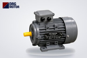
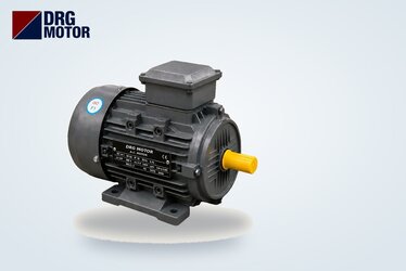
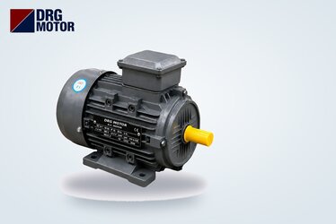
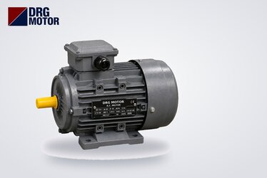
- DRG-90L-4 – 1.5 kW – 1500 rpm – 90L cast iron
- DRG-112M-4 – 4 kW – 1500 rpm – 112M cast iron
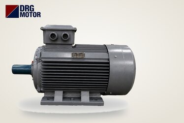
- DRG-132M-4 – 7.5 kW – 1500 rpm – 132M cast iron
- DRG-160M-4 – 11 kW – 1500 rpm – 160M cast iron
- DRG-200L-4 – 30 kW – 1500 rpm – 200L cast iron
Click to see current prices and order these motors nowSEE PRICES →
Frequently Asked Questions
What should an overload relay be set to?
For a direct-on-line motor, set it to the rated current on the nameplate. For example, 15 A at 380 V for the 7.5 kW, 1500 rpm DRG-132M-4. With star-delta starting, if the relay sees the phase current, the setting is In/√3, about 8.66 A.
What is the difference between an overload relay and a fuse?
The fuse and the magnetic trip of a circuit breaker open instantly at very high currents such as short circuits. The overload relay detects overloads slightly above rated current lasting for minutes, as well as phase loss. One does not replace the other; both are used together in a motor circuit.
Why does the overload relay keep tripping?
The most common causes are mechanical overload, phase loss or a loose connection, low supply voltage, a wrong setting (especially with star-delta) and a trip class too low for a long start. Start by measuring the three phase currents and comparing them with the nameplate current.
Where is the overload relay connected in star-delta starting?
In common practice the relay is connected at the output of the main contactor, in the line going to the motor's U1-V1-W1 terminals, and sees the phase current; the setting is In/√3. If the relay is on the supply side, the setting is In. Check your diagram.
For help with your motor's nameplate current and overload setting, contact us at +90 (542) 666 11 11 or [email protected], or use our contact page. You can browse all motor models among the 120 models in our online store.