 English
 Le français
 Türkçe





A hand-off-auto circuit lets one motor be controlled from two different sources: with the selector in HAND the motor answers the start and stop buttons, in AUTO it follows an external contact such as a float switch, pressure switch or time switch, and in OFF no command can start it. The fuse and the overload relay stay in circuit in both modes, so protection does not depend on the selected mode.
Safety: This content is for technical information only. Wiring, measurement and commissioning must be carried out by qualified electrical personnel, following lock-out and verification of de-energised state, and in line with the motor and device manufacturer's documentation.
What is a hand-off-auto circuit for?
Most pumps, fans, compressors and conveyors normally run on their own: the pump fills the tank when the level drops, the compressor cuts in when pressure falls. During maintenance, first start-up or a sensor fault, however, the operator must be able to run and stop the motor by hand. The three-position selector on the panel door chooses between the two. In practice it brings two benefits: the plant keeps running when a sensor fails, and the automatic command cannot start the motor unexpectedly while someone is working on the machine.
The circuit is built on top of the familiar start-stop self-holding circuit. The difference is that the path to the K1 coil splits in two and the selector decides which path is used. The self-holding logic is also covered in detail in the star-delta control circuit article.
Selector switch: positions and contact table
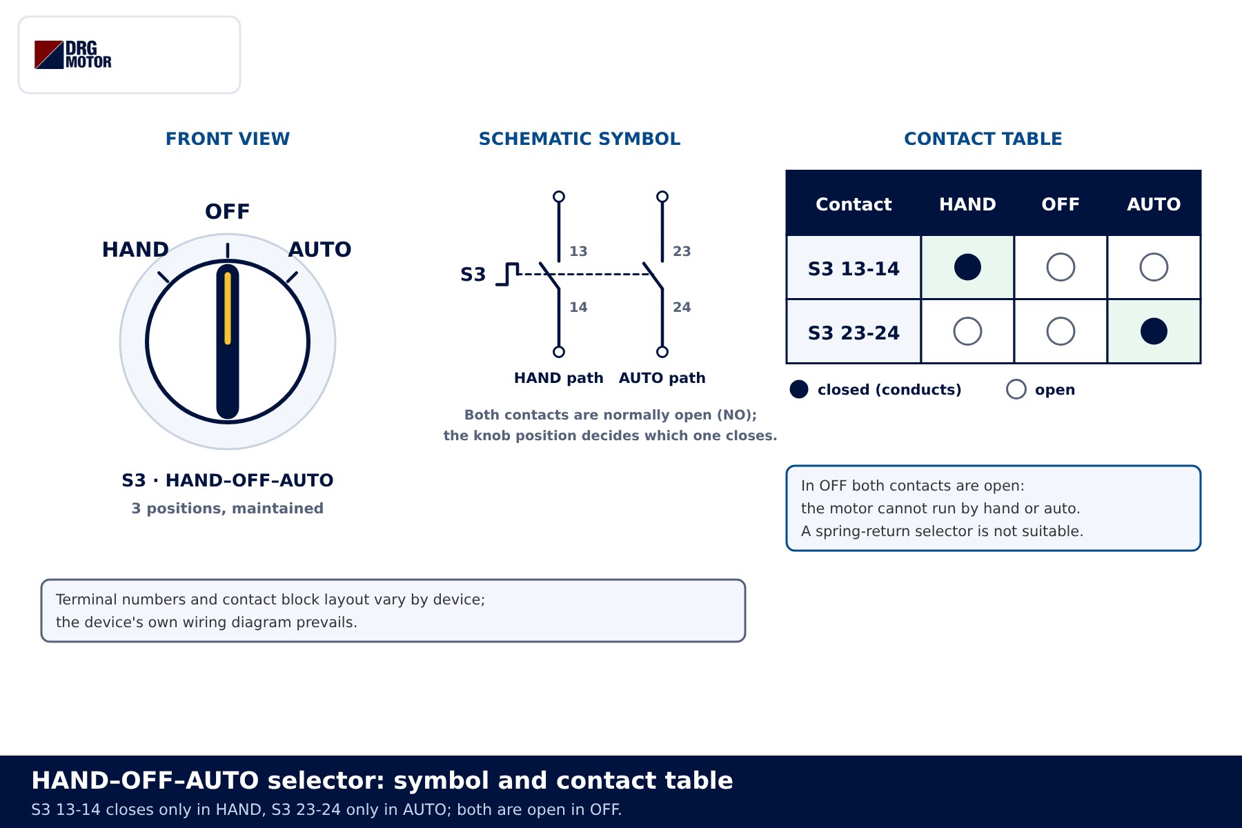
The selector switch (S3 in the diagrams) is a maintained rotary switch: it stays where it is left. It carries two normally open contact blocks. The legend usually reads HAND–OFF–AUTO; panels built for other markets may show EL–0–OTO or MAN–0–AUTO. The schematic symbol shows the rotary actuator and the dashed mechanical link joining both contacts, while the small contact table beside it tells you which contact closes in which position.
| Position | S3 13-14 (hand path) | S3 23-24 (auto path) | Result |
|---|---|---|---|
| HAND | closed | open | Motor responds to S2/S0 |
| OFF | open | open | No command can start the motor |
| AUTO | open | closed | Motor follows contact B1 |
Two details matter here. First, the two contacts are never closed at the same time, so the paths cannot interfere. Second, a spring-return selector is not suitable, because it would not stay in AUTO once released. Terminal numbers and the layout of contact blocks vary by device; the device's own wiring diagram prevails.
Power circuit: one contactor for both modes
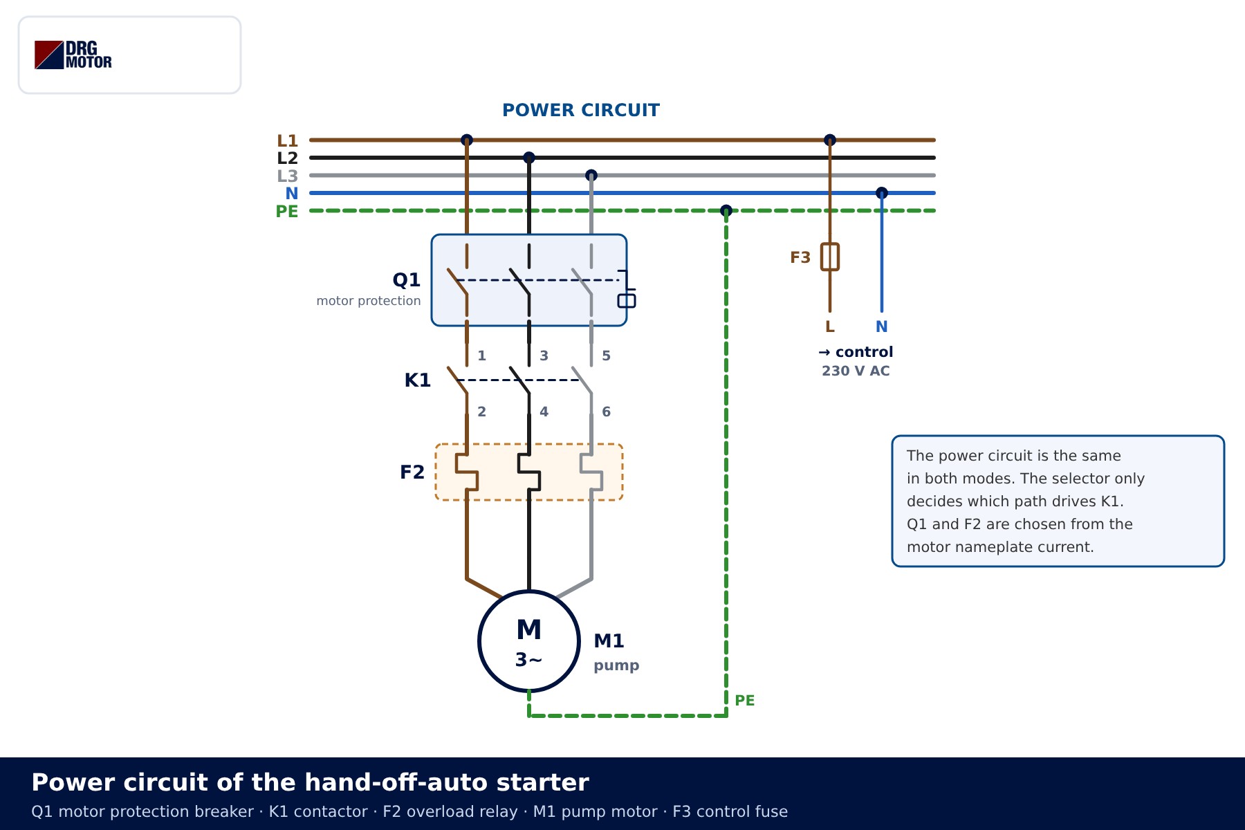
Nothing changes on the power side. Phases L1, L2 and L3 pass through Q1 motor protection breaker, the K1 main contacts 1-2, 3-4, 5-6 and the heating elements of overload relay F2 before reaching motor M1; the PE conductor goes straight to the motor frame. The control circuit is fed from one phase through fuse F3 and from the neutral. Selecting a mode only changes which path drives the K1 coil; the line feeding the motor is identical in both modes.
📄 Download Wiring Diagram PDF A4 printable PDF of the diagrams and tables (no sign-up)
Click to see current electric motor prices and order nowSEE PRICES →
Control circuit: common chain, hand path, auto path
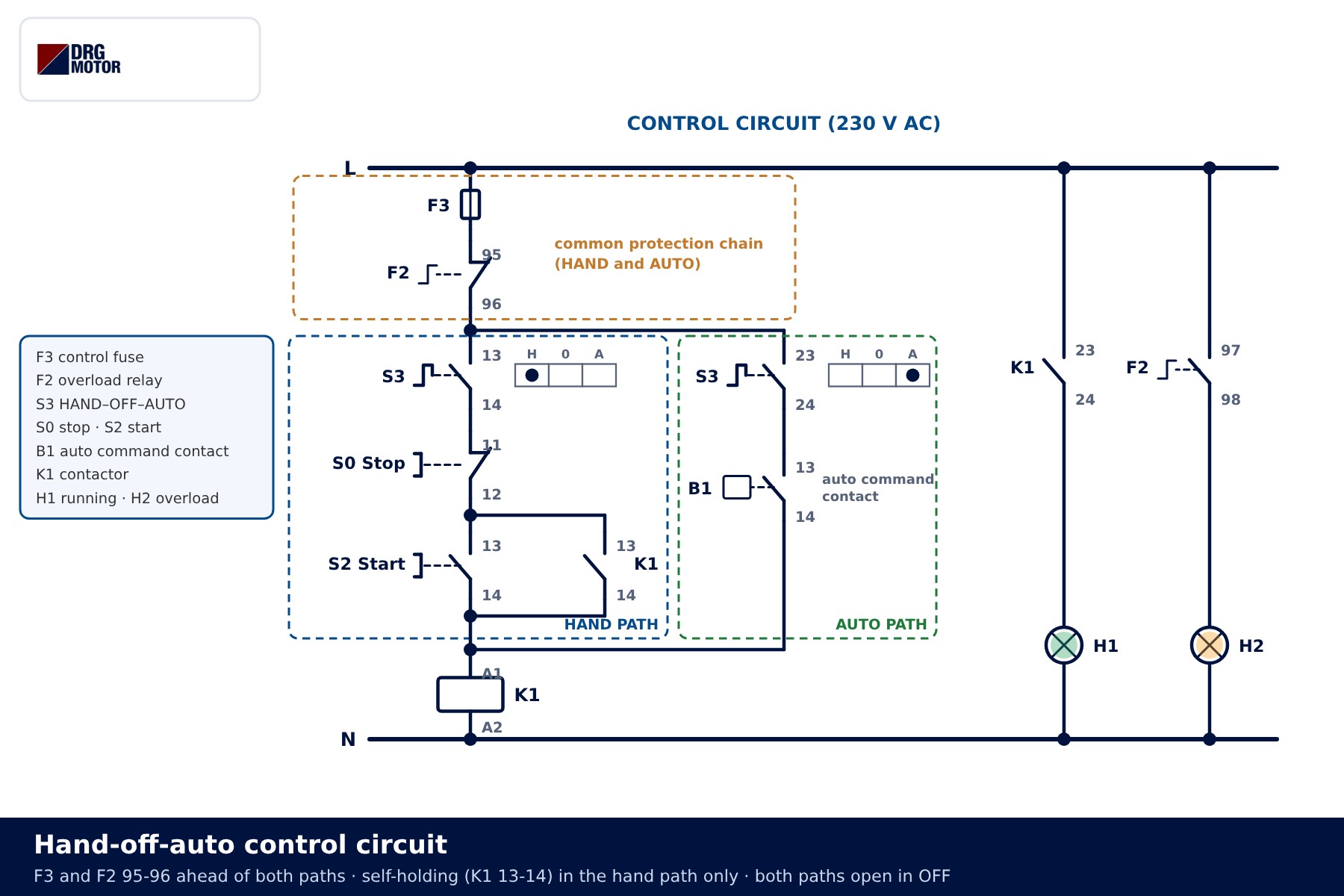
It helps to read the control circuit in three parts. The upper rail is L, the lower rail is N; filled dots mark electrical junctions, and crossings without a dot are not connected.
Common protection chain
From the L rail the conductor passes first through control fuse F3, then through the normally closed contact 95-96 of overload relay F2. The selector sits below this chain. As a result, when the overload trips the motor stops whatever the mode. Wiring the overload contact inside the auto path only, for instance just behind B1, leaves the motor unprotected in HAND, and it is one of the most common field mistakes.
Hand path
After S3 13-14 come stop button S0 (NC, 11-12) and start button S2 (NO, 13-14). Auxiliary contact K1 13-14, wired in parallel with S2, provides self-holding: when S2 is released the coil stays energised through this contact. Pressing S0 breaks the hold.
Auto path
Behind S3 23-24 there is only the automatic command contact B1. There is no self-holding here, because a float or pressure switch keeps its contact closed for as long as the demand lasts; the motor runs while B1 is closed and stops when it opens. If the command comes from a PLC as a short pulse, this arrangement is not enough and separate relay logic is needed to hold the pulse.
Pilot lamps
Running lamp H1 is fed through K1 23-24, and fault lamp H2 through the normally open contact 97-98 of F2. Some panels add an "AUTO selected" lamp using a third contact on S3.
| Device | Function | Terminals |
|---|---|---|
| Q1 motor protection breaker | Short-circuit and overcurrent protection of the power circuit | 1-2, 3-4, 5-6 |
| F3 control fuse | Protects the control circuit | — |
| F2 overload relay | Opens the common chain on overload and lights H2 | 95-96 NC, 97-98 NO |
| S3 selector switch | Selects HAND / OFF / AUTO path | 13-14, 23-24 |
| S0 / S2 buttons | Manual stop / start | 11-12 NC / 13-14 NO |
| B1 automatic command contact | Float switch, pressure switch or time switch | volt-free contact |
| K1 contactor | Connects the motor to the supply, provides self-holding | A1-A2, 13-14, 23-24 |
Step-by-step sequence and state table
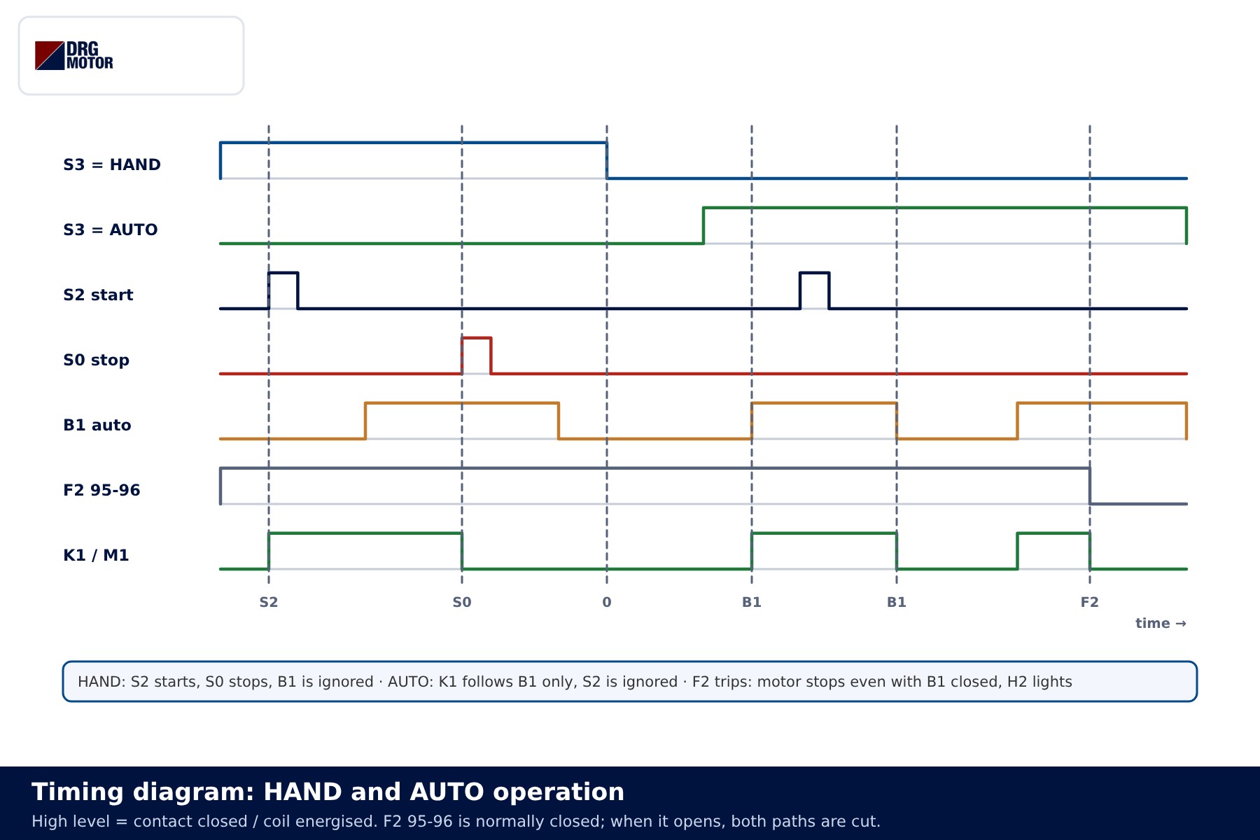
The timing diagram shows how the same circuit behaves over a shift. The sequence below matches the events in the diagram:
- S3 in HAND, S2 pressed: K1 picks up, the motor starts and K1 13-14 closes. When S2 is released the motor keeps running.
- B1 closes meanwhile: nothing happens, because S3 23-24 is open.
- S0 pressed: the coil is de-energised, the hold is broken and the motor stops.
- S3 turned to AUTO, B1 closes: K1 picks up; when B1 opens K1 drops out. Pressing S2 has no effect in this mode.
- Overload trips: 95-96 opens, the motor stops even though B1 is closed, and H2 lights.
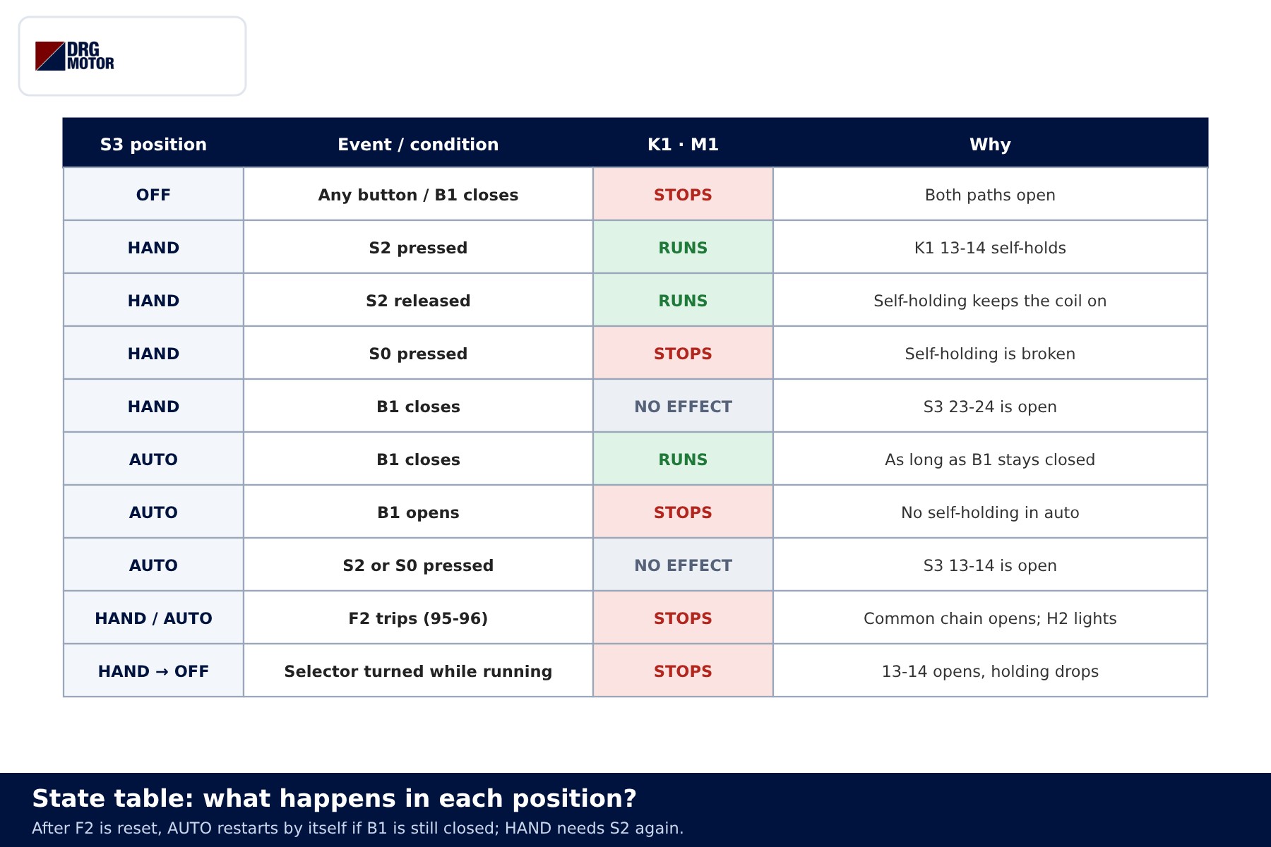
Two rows of the table deserve attention. The first is power loss and overload reset: in AUTO, if B1 is still closed, the motor restarts by itself; in HAND the hold has dropped, so S2 must be pressed again. This is why a manually reset overload relay and an "automatic start" warning at the machine are recommended. Second, if the selector is turned to OFF while the motor runs in HAND, 13-14 opens and the hold is lost for good; turning back to HAND will not restart the motor. The OFF position does not isolate the motor for maintenance; Q1 must be opened and locked before any work on the motor.
Pump example: tank filling with a float switch
Take a 2.2 kW pump filling a water tank. Float switch B1 closes when the water falls to the low level and opens when it reaches the high level. With the selector in AUTO the pump cycles between these two levels on its own; when a technician wants to test the pump or fill the tank after a float failure, he turns the selector to HAND and uses S2/S0.
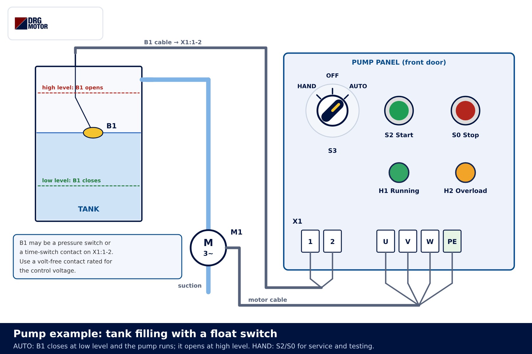
Two terminals on the terminal strip (X1:1-2 in the drawing) are all B1 needs. The volt-free output of a pressure switch, a time switch or a level relay can be wired to the same two terminals without changing the control circuit. The contact must suit the control voltage and the coil current. For long sensor cables in the field, lowering the control voltage to 24 V and adding an interface relay is a common choice. If the pump starts too often, the cause is usually not the control circuit but the level difference or the pressure tank; see booster pump motor starts too often. Typical reasons behind a burnt pump motor are discussed in why booster pump motors burn out.
Common wiring mistakes
| Symptom | Likely cause |
|---|---|
| In AUTO the motor starts with B1 but does not stop when the overload trips | F2 95-96 is wired into the hand path only, not the common chain |
| In HAND the motor stops when S2 is released | K1 13-14 is not in parallel with S2, or an NC auxiliary was used |
| In OFF the motor runs when B1 closes | Wrong contact block on the selector, or B1 wired around the selector |
| Switching from HAND to AUTO does not stop the motor | Self-holding contact wired above the selector, so the coil stays fed even with 13-14 open |
| In AUTO the motor starts and stops in short cycles | Narrow B1 differential, float/pressure switch setting or a loose sensor wire |
| Control fuse blows when S0 is pressed | Wrong jumper between S0 and K1 13-14 shorting phase to neutral |
Device and motor selection examples
Contactor, overload relay and motor protection breaker are chosen from the rated current on the motor nameplate; one contactor size does not fit every job. You can read the current in the motor current chart and size the protection with the overload, fuse and contactor selection tool. Utilisation category and number of operations matter too; see motor panel contactor selection. The overload setting follows the nameplate current; for details see overload relay setting. For the supply cable, the motor cable size calculator takes length and installation method into account.
| Application | Automatic command | Motor example |
|---|---|---|
| Tank filling pump | Float switch (B1) | 1.5–2.2 kW, 3000 rpm |
| Booster set | Pressure switch | 2.2–4 kW, 3000 rpm |
| Irrigation pump | Time switch | 4–7.5 kW, 3000 rpm |
| Ventilation fan | Thermostat or time switch | 0.75–3 kW, 1500 rpm |
These values are examples; the power and speed requested by the pump maker prevail. DRG motors up to 3 kW are wound 230/400 V and from 4 kW 400/690 V; on a 400 V supply small motors are connected in star and larger ones in delta.
Send a photo of your current motor nameplate and we will find the suitable DRG model together.Send on WhatsApp
DRG motors for pump and fan duty
DRG Motor is a manufacturer, supplier and seller of electric motors. The 2-pole three-phase models below cover the power range often found on centrifugal pumps driven from hand-off-auto panels; all are IP55 with class F insulation. Selector switches, contactors, overload relays, float switches and pressure switches are not sold by DRG; please contact your panel component supplier for these. Other power and speed options are listed on the three-phase asynchronous electric motors page and in the online store.
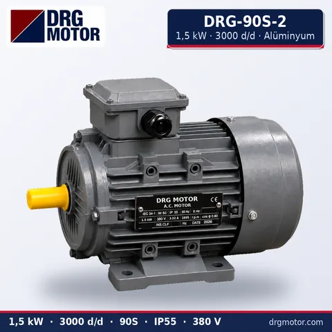
1.5 kW Three-Phase Motor 3000 rpm – DRG-90S-2 Aluminium
- 1.5 kW · 3000 rpm (2 poles)
- Aluminium frame · IEC 90S
- Mounting: B3 · B5 · B14 · B35
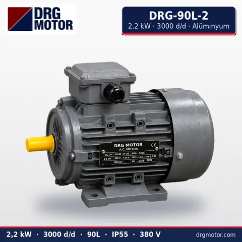
2.2 kW Three-Phase Motor 3000 rpm – DRG-90L-2 Aluminium
- 2.2 kW · 3000 rpm (2 poles)
- Aluminium frame · IEC 90L
- Mounting: B3 · B5 · B14 · B35
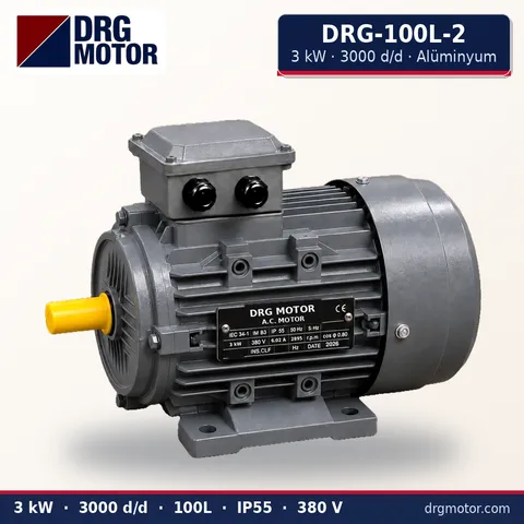
3 kW Three-Phase Motor 3000 rpm – DRG-100L-2 Aluminium
- 3 kW · 3000 rpm (2 poles)
- Aluminium frame · IEC 100L
- Mounting: B3 · B5 · B14 · B35
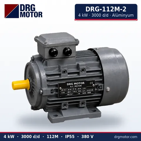
4 kW Three-Phase Motor 3000 rpm – DRG-112M-2 Aluminium
- 4 kW · 3000 rpm (2 poles)
- Aluminium frame · IEC 112M
- Mounting: B3 · B5 · B14 · B35
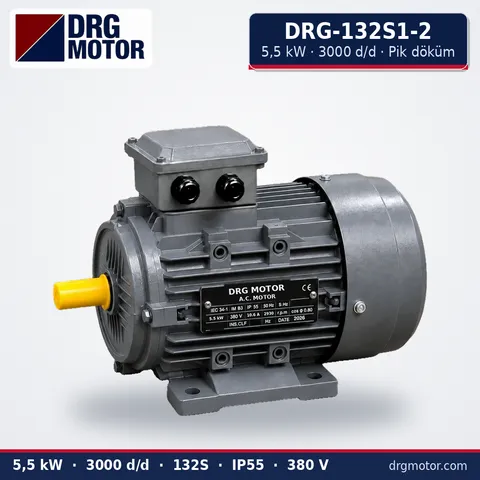
5.5 kW Three-Phase Motor 3000 rpm – DRG-132S1-2 Cast Iron
- 5.5 kW · 3000 rpm (2 poles)
- Cast iron frame · IEC 132S
- Mounting: B3 · B5 · B14 · B35
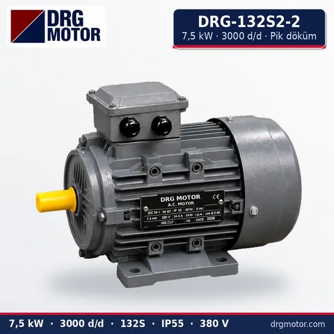
7.5 kW Three-Phase Motor 3000 rpm – DRG-132S2-2 Cast Iron
- 7.5 kW · 3000 rpm (2 poles)
- Cast iron frame · IEC 132S
- Mounting: B3 · B5 · B14 · B35
Click to see current prices for these motors and order nowSEE PRICES →
Frequently asked questions
Why must the overload contact be in the common line?
Because the motor is fed by the same contactor K1 in both modes and carries the same overload risk. With F2 95-96 ahead of the selector, a trip cuts both the HAND and the AUTO path.
Why is there no self-holding in the auto path?
Float switches, pressure switches and time switches keep their contact closed for as long as the demand lasts. With self-holding added, the motor would not stop when B1 opens and the tank would overflow or the pressure keep rising.
Is turning the selector to OFF enough for maintenance?
No. OFF only interrupts the control circuit; the power circuit is still live. Before maintenance Q1 must be opened, locked and the de-energised state verified by measurement.
Will the motor restart by itself after a power cut?
Not in HAND, because the hold drops and S2 is needed again. In AUTO, if B1 is closed, the motor restarts on its own; whether the machine allows this must be covered in the risk assessment.
Can the same circuit use 24 V DC control?
Yes. The logic is the same; only the K1 coil, the lamps and the B1 contact are chosen for 24 V DC and the control side is fed from a power supply.
📄 Download Wiring Diagram PDF A4 printable PDF of the diagrams and tables (no sign-up)





