 English
 Le français
 Türkçe





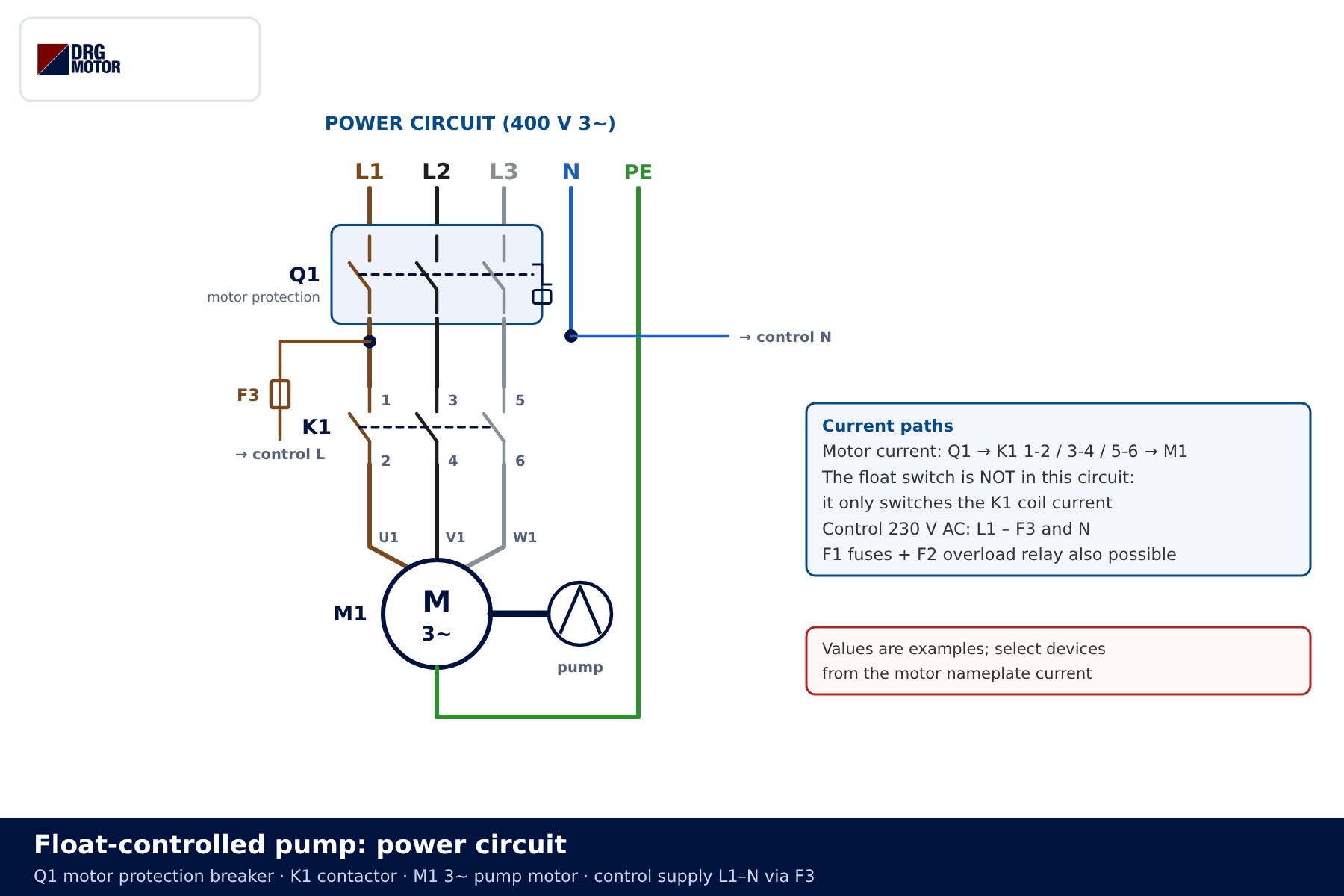
In a float-switch control for a three-phase pump, the float never drives the motor directly: it only switches the coil current of contactor K1, and the motor current flows through K1’s main contacts. For tank filling you use the contact that closes with the float down (C–NC), so the pump runs when the level falls; for sump or tank emptying you use the contact that closes with the float up (C–NO), so the pump runs when the level rises.
Safety notice: This content is for technical information only. Wiring, measurement and commissioning must be carried out by qualified electrical personnel, following lock-out and verification of de-energised state, and in line with the motor and device manufacturer's documentation.
This article covers the two cases with separate diagrams: (A) tank filling and (B) sump/tank emptying (drainage). You will find the power circuit, the float contact type, both control circuits, a tank section, a level state table and a hysteresis diagram. The diagrams are examples; terminal names and core colours vary by device, and the device’s own wiring diagram prevails.
What components does a float-controlled pump circuit use?
The circuit has two layers. In the power circuit, L1-L2-L3 pass through the Q1 motor protection breaker and K1’s 1-2 / 3-4 / 5-6 main contacts to the M1 pump motor. The control circuit runs on 230 V AC (here taken from L1 and N through control fuse F3) and drives the K1 coil. The float switch lives only in this second circuit. Routing three-phase motor current through a float contact is wrong on two counts: it cannot break all three phases, and its contact rating is far too small.
| Component | Terminals | Role in the circuit |
|---|---|---|
| Q1 motor protection breaker | 1-2 / 3-4 / 5-6 + auxiliary and trip-signal contacts (names vary by device) | Short-circuit and overload protection; F1 fuses + F2 overload relay are an alternative |
| F3 control fuse | single pole | Protects the control wiring |
| K1 contactor | A1-A2 coil, 1…6 main, 13-14 auxiliary | Connects the motor to the supply; 13-14 drives the running lamp |
| B1 float switch | C (common), NO, NC | Opens or closes the K1 coil path according to level |
| S2 MAN-0-AUTO selector (optional) | 13-14 MAN, 23-24 AUTO | 0 stops, MAN bypasses the float, AUTO hands control to the float |
| H1 / H2 lamps | X1-X2 | H1 pump running, H2 overload fault |
| M1 pump motor | U1 V1 W1 + PE | Three-phase induction motor; star or delta per nameplate |
The protection order never changes: short-circuit protection, contactor, overload protection, motor. The difference between Q1 and a separate overload relay is explained in overload relay vs motor protection breaker, and contactor sizing in choosing a contactor for a motor panel. For a first estimate, try the overload, fuse and contactor selection tool.
Float switch contact type: C, NO and NC cores
Most cable float switches contain a changeover (C/O) contact with three cores: a common (C), an NO core that closes with the float up and an NC core that closes with the float down. Which colour belongs to which terminal depends on the device. Brown, black and blue are common, but treating any colour scheme as a “standard” leads to mistakes. Two-core floats have a single pair, and whether they suit filling or emptying depends on the device design or its mounting.
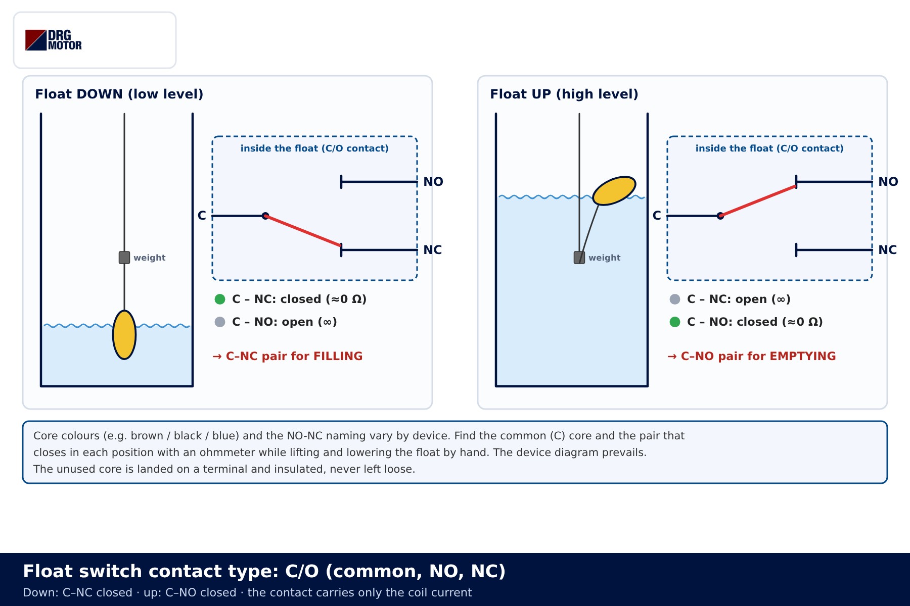
Measure before you wire: let the float hang down and find the closed pair with an ohmmeter, then turn the float upside down and repeat. The core that is part of the closed pair in both positions is C. Never leave the unused core loose; land it on a spare terminal and insulate it. The contact rating is printed on the float label; because it only carries coil current it is usually adequate for a contactor coil, but check it anyway.
📄 Download Wiring Diagram PDF A4 printable PDF of the diagrams and tables (no sign-up)
Click to see current electric motor prices and order nowSEE PRICES →
A) Tank filling control circuit
When filling, the goal is to refill the tank once it is low and stop once it is full. The C–NC pair is used: when the level drops to the lower limit and the float hangs down, the contact closes, K1 picks up and the pump runs. As the water rises and lifts the float, the contact opens, K1 drops out and the pump stops. The control path reads L – F3 – F2/Q1 95-96 – S2 – B1 C–NC – K1 A1-A2 – N.
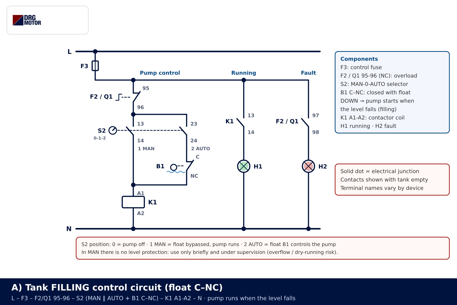
Without S2, the B1 contact sits directly between 95-96 and K1 A1. With S2, the AUTO position (23-24) routes current through the float, while MAN (13-14) bypasses the float so the pump can be run by hand. In MAN there is no level protection at all: the tank can overflow, or the pump can run dry if the source well is empty. Use MAN only briefly and under supervision. A filling pump may also find no water on the source side; dry-running protection is added for that, and it will be covered in a separate article.
B) Sump and tank emptying (drainage) circuit
Emptying works the other way round: in a wastewater pit, a rainwater sump or a basement drain, the pump must start when the water rises and stop once the level has fallen. This time the C–NO pair is used. When the float lifts, the contact closes and K1 picks up; when the level reaches the lower limit and the float hangs down again, the contact opens and the pump stops.
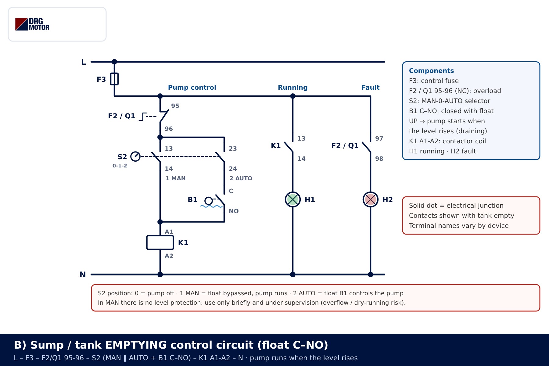
The power circuit, S2, H1 and H2 are the same; only the float pair changes. That is exactly why the most common site error is applying a filling diagram to a drainage sump, or the reverse. Keep the lower level above the pump inlet; otherwise the pump runs on air for a while at the end of every cycle.
📄 Download Wiring Diagram PDF A4 printable PDF of the diagrams and tables (no sign-up)
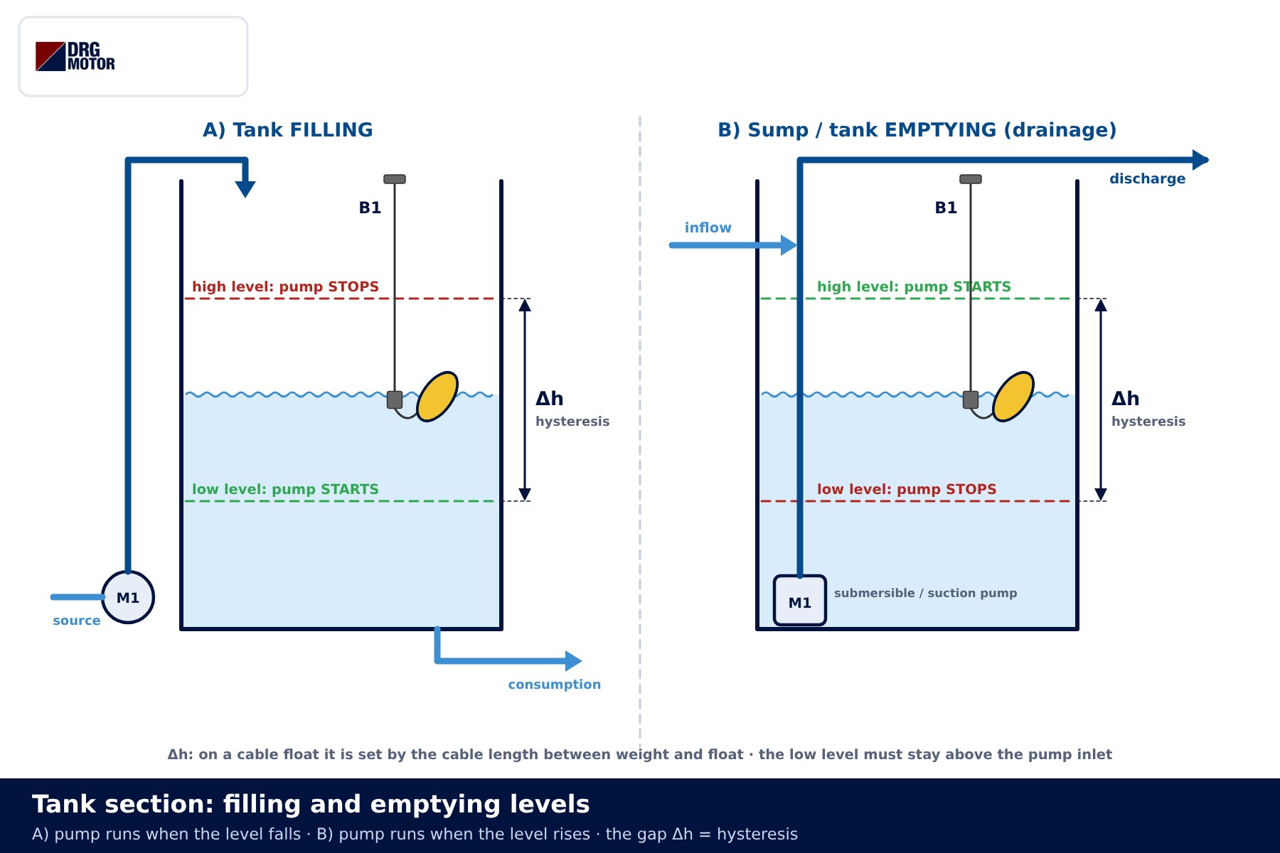
Tank section, level state table and hysteresis
A float switch does not switch on and off at the same level. On a cable float, the cable passes through a weight, and the free cable length between the weight and the float sets how far the float has to rise before it tips over and changes state. That gap (Δh) is the hysteresis. Without it, the pump would start and stop many times within seconds as the surface rippled around the limit.
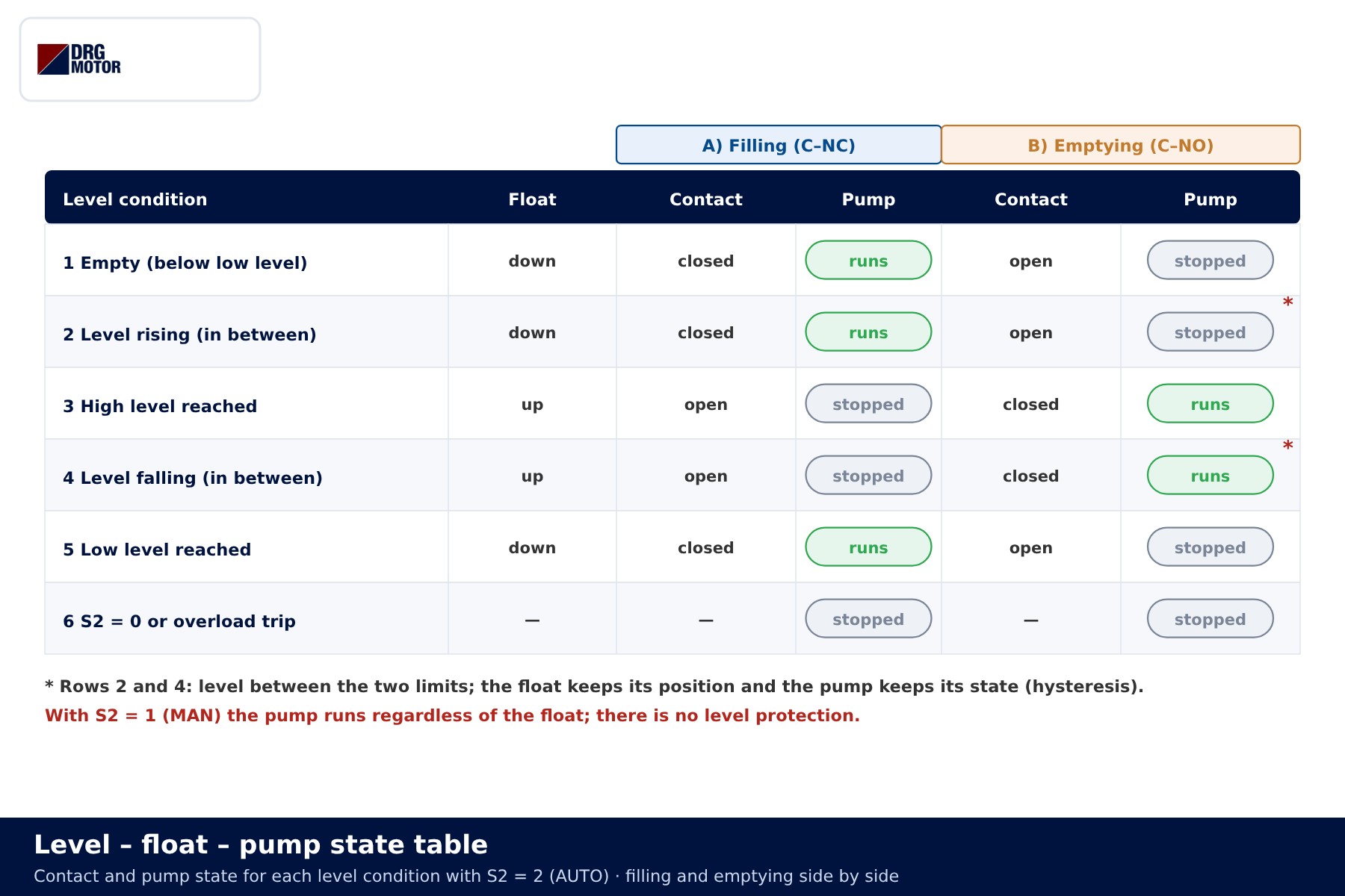
| Level condition | Float | A) Filling pump | B) Emptying pump |
|---|---|---|---|
| Below the low level | down | runs (C–NC closed) | stopped (C–NO open) |
| Between limits, rising | down | keeps running | stays stopped |
| High level reached | up | stops (C–NC open) | runs (C–NO closed) |
| Between limits, falling | up | stays stopped | keeps running |
| S2 = 0 or overload trip | — | stopped | stopped |
The hysteresis diagram shows the pump changing state only at the two limits and holding its previous state in between. A small Δh makes the pump cycle often, and frequent starts wear both the motor and the contactor contacts. A large Δh leaves part of the tank unused. Frequent cycling is also one of the main causes of short motor life in booster sets; see why booster pump motors burn out.
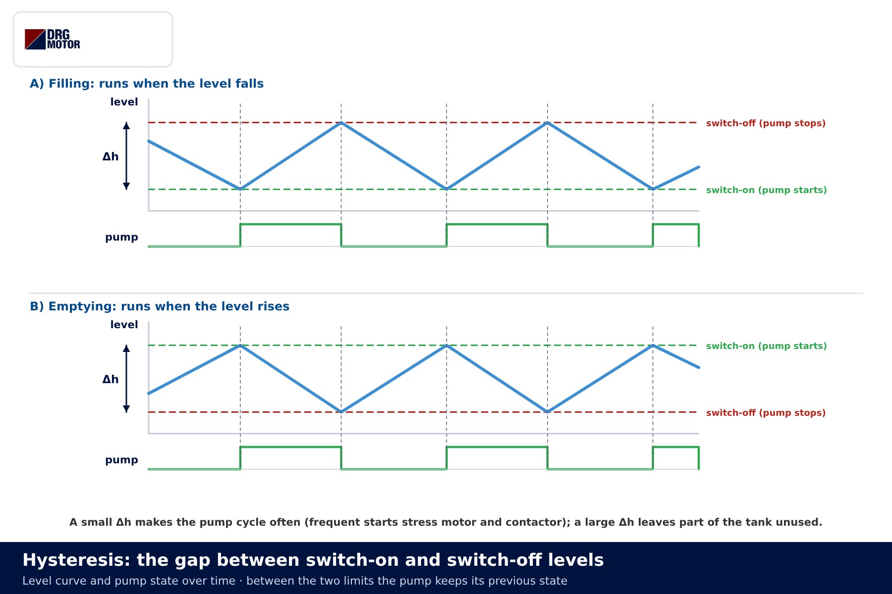
With two separate floats (one low, one high) or an electrode level relay, the hysteresis is built in the control circuit using a K1 self-holding contact; that solution will get its own article.
Step-by-step operation (filling example)
- Tank empty, S2 on AUTO: float down, C–NC closed. With F2/Q1 95-96 closed, the K1 coil is energised, the pump runs and H1 lights.
- Level rising: the float does not change state until its cable is taut; the pump keeps running.
- High level: the float tips over, C–NC opens. K1 drops out, the pump stops and H1 goes off.
- Consumption begins: as the level falls the float stays up; the pump stays off until the lower limit.
- Low level: the float hangs down, C–NC closes and the cycle starts again.
- Overload: if the relay trips, 95-96 opens and K1 drops; 97-98 closes and H2 lights. Once the fault is cleared and the relay reset, the pump restarts by itself if the float contact is still closed. This is a property of float circuits worth knowing.
- Power cut and return: with no self-holding, the pump restarts on its own if the float position calls for it. Before working on the pump, switch off and lock Q1.
Common wiring mistakes
| Symptom | Likely cause |
|---|---|
| Pump stops when the tank is empty and runs when it is full | C–NO and C–NC pairs swapped; wrong core for the application |
| Pump never stops | S2 left on MAN, float cable snagged, or K1 contacts welded |
| Pump starts and stops very often | Free cable too short (small Δh), float sitting in the turbulence of the inlet pipe |
| Float contact burns out quickly | Motor current routed through the float without a contactor, or contact rating exceeded |
| Contactor hums or chatters | Coil voltage does not match the control voltage, loose terminal |
| Overload relay trips often | Phase loss, jammed pump, wrong relay setting or motor too small for the pump load |
When the overload relay or fuses trip repeatedly, the cause is usually on the pump and motor side: see why an electric motor trips its overload relay and why phase loss is dangerous for a motor.
Selection examples
- 2.2 kW, 3000 rpm, 230/400 V pump motor on a 400 V supply: connect the motor in star. Q1 and K1 are chosen from the rated current on the nameplate and the AC-3 utilisation category; the overload is set from the nameplate current.
- 5.5 kW, 3000 rpm, 400/690 V motor on a 400 V supply: connect in delta. Where direct-on-line starting does not suit the supply, consider methods such as the star-delta power circuit; the float contact then goes into the start branch of the star-delta control.
- Cable: the size depends on run length, installation method and protective device. The motor current chart gives the rated current and the motor cable size calculator a starting value.
- Float cable: if the tank is far from the panel, run the control cable separately and use a junction box suited to damp locations.
Send a photo of your current motor nameplate and we will find the suitable DRG model together.Send on WhatsApp
DRG motors for float-controlled pump circuits
DRG Motor is an electric motor manufacturer, supplier and seller. Below are some three-phase IEC motors in the 3000 rpm class often found on centrifugal pumps; flange, shaft and speed are chosen to suit the pump itself. Float switches, contactors, overload relays and selectors are not sold by DRG; please contact your panel component supplier for those. Other ratings and speeds are listed on the three-phase asynchronous electric motors page and in the online store.
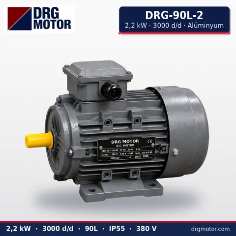
2.2 kW Three-Phase Motor 3000 rpm – DRG-90L-2 Aluminium
- 2.2 kW · 3000 rpm (2 poles)
- Aluminium frame · IEC 90L
- Mounting: B3 · B5 · B14 · B35
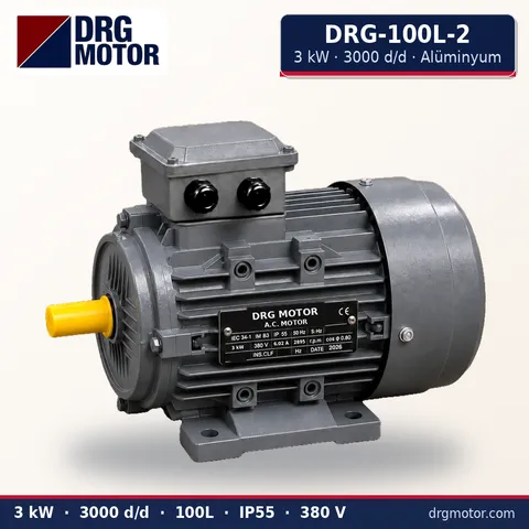
3 kW Three-Phase Motor 3000 rpm – DRG-100L-2 Aluminium
- 3 kW · 3000 rpm (2 poles)
- Aluminium frame · IEC 100L
- Mounting: B3 · B5 · B14 · B35
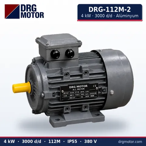
4 kW Three-Phase Motor 3000 rpm – DRG-112M-2 Aluminium
- 4 kW · 3000 rpm (2 poles)
- Aluminium frame · IEC 112M
- Mounting: B3 · B5 · B14 · B35
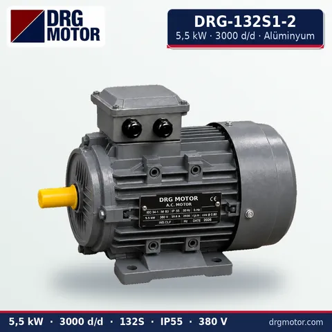
5.5 kW Three-Phase Motor 3000 rpm – DRG-132S1-2 Aluminium
- 5.5 kW · 3000 rpm (2 poles)
- Aluminium frame · IEC 132S
- Mounting: B3 · B5 · B14 · B35
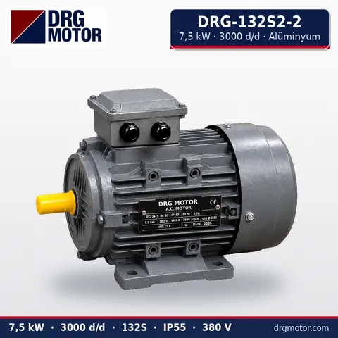
7.5 kW Three-Phase Motor 3000 rpm – DRG-132S2-2 Aluminium
- 7.5 kW · 3000 rpm (2 poles)
- Aluminium frame · IEC 132S
- Mounting: B3 · B5 · B14 · B35
Click to see current prices for these motors and order nowSEE PRICES →
Frequently asked questions
Can a float switch start a three-phase pump directly?
No. A float contact cannot break all three phases and is not rated for motor current. In a correct installation the float only switches the K1 contactor coil, and motor current flows through the contactor’s main contacts.
Which cores are used for filling?
The pair that closes with the float down, C–NC. For emptying, use the C–NO pair that closes with the float up. Colours vary by device, so confirm the cores with an ohmmeter before connecting.
Why does the pump start and stop so often?
Usually the gap between the switch-on and switch-off levels (the hysteresis) is too small. On a cable float you increase it by lengthening the free cable between the weight and the float. Also keep the float away from inlet water and wave action.
Is a MAN-0-AUTO selector required?
No, but it is handy for maintenance and testing. As MAN offers no level protection, run the pump in MAN only briefly and under supervision.
Why does the pump restart by itself after the overload is reset?
This circuit has no self-holding; the float contact feeds the K1 coil directly. If the contact is still closed, the pump starts the moment the relay is reset. Switch off and lock Q1 before working on the pump.





