 English
 Le français
 Türkçe





To reverse a single-phase induction motor, swap the leads of one winding only – normally the auxiliary winding (Z1 and Z2 in our examples), which is the one wired in series with the capacitor. Swapping L and N does not change the direction. Capacitor type and value always come from the motor nameplate, and the connection follows the motor’s own terminal diagram.
Safety notice: This content is for technical information only. Wiring, measurement and commissioning must be carried out by qualified electrical personnel, following lock-out and verification of de-energised state, and in line with the motor and device manufacturer's documentation.
Below we draw permanent split capacitor (PSC), capacitor-start and two-capacitor motors separately, then show reversing with terminal links and with a pair of contactors. Lead names U1-U2 (main winding) and Z1-Z2 (auxiliary winding) are representative; actual names and colours vary by manufacturer.
What do the main and auxiliary windings do?
A single-phase supply does not create a rotating field. A motor with only one winding cannot start on its own; give the shaft a push and it runs in whichever direction it was pushed. That is why the stator carries two windings. The main winding does the work and sits directly across L–N. The auxiliary winding is placed at an offset in the stator and its current is phase-shifted by a capacitor. Together they produce a field that starts to rotate, and the rotor follows it. For background, see why single-phase motors need a capacitor.
| Part | Example lead name | Function |
|---|---|---|
| Main winding | U1-U2 | Connected across L–N; the running winding |
| Auxiliary winding | Z1-Z2 | In series with the capacitor; sets starting and direction |
| Run capacitor (Cr) | C1 | Stays in the auxiliary circuit at all times |
| Start capacitor (Cs) | C2 | In circuit only while the motor starts |
| Centrifugal switch | B1 | Opens the starting circuit as speed rises; inside the motor |
| Protective conductor | PE | Earths the motor frame |
Three motor types and their wiring diagrams
The nameplate and terminal box usually tell you the type: one capacitor and two lead groups normally means PSC, while two capacitors on the frame or a faint click from inside when the motor slows down points to a starting circuit. If in doubt, check the nameplate diagram before opening anything.
Permanent split capacitor (PSC) motor
The auxiliary winding and run capacitor C1 remain connected while the motor runs; there is no centrifugal switch. The design is simple and quiet but starting torque is modest, so it suits fans, extractors and light loads. Some PSC motors have two identical windings and three leads; direction is then chosen by which winding the capacitor is connected to.
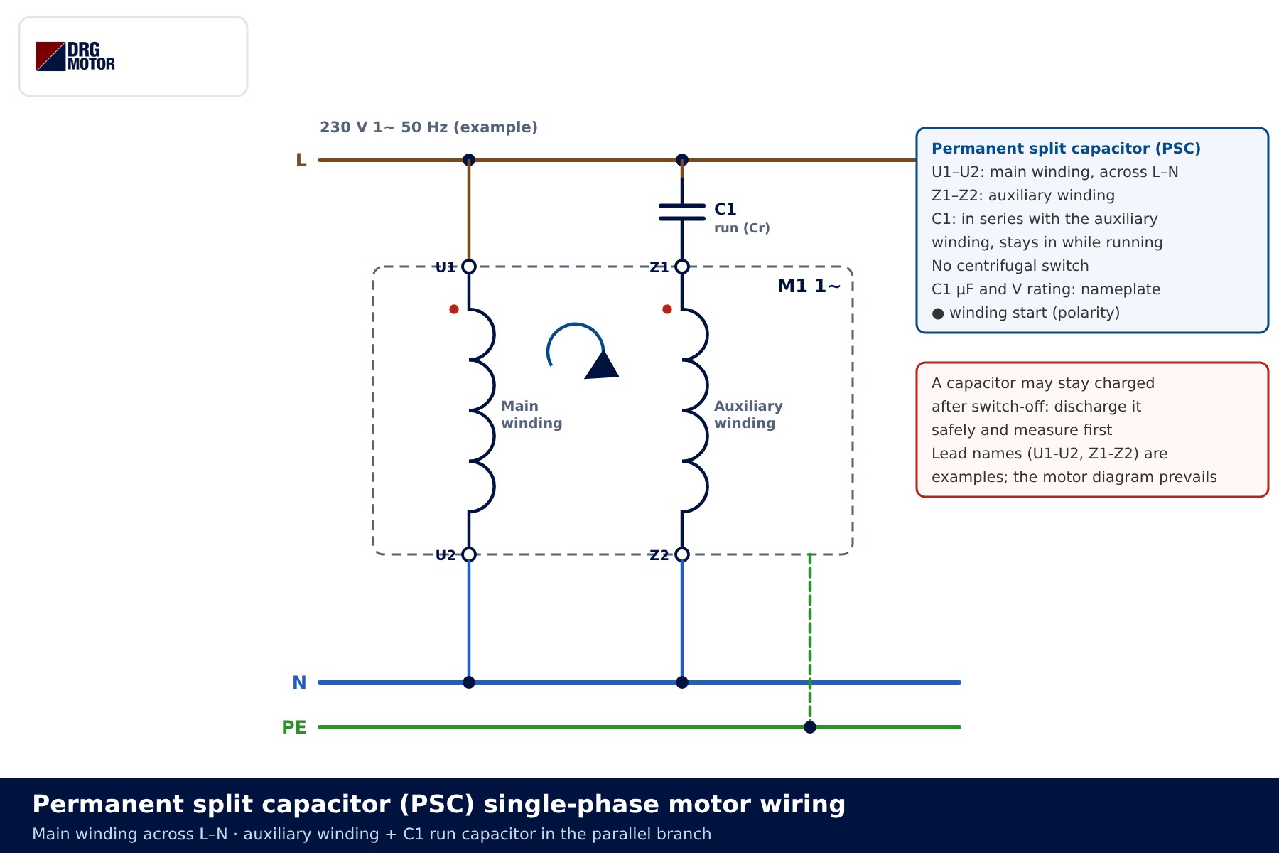
Capacitor-start motor with centrifugal switch
The auxiliary winding, start capacitor C2 and centrifugal switch B1 are wired in series. As the motor accelerates, B1 opens and the motor carries on with the main winding alone. A start capacitor is only rated for short periods; if B1 sticks closed, the capacitor and auxiliary winding overheat quickly. You find this type on compressors, pumps and machines that start under load.
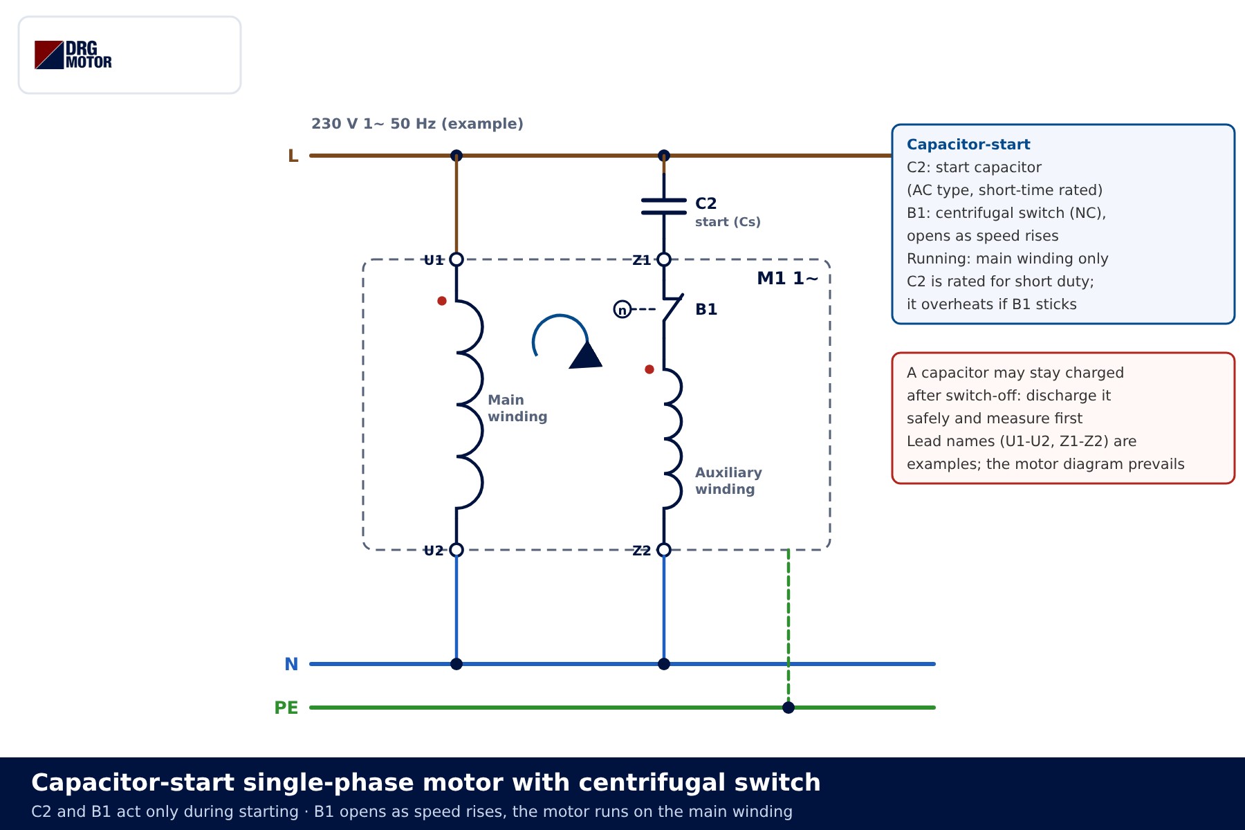
Two-capacitor (start + run) motor
Run capacitor C1 is always connected to the auxiliary winding; start capacitor C2 is added in parallel through B1 during starting. The result is high starting torque together with smooth running.
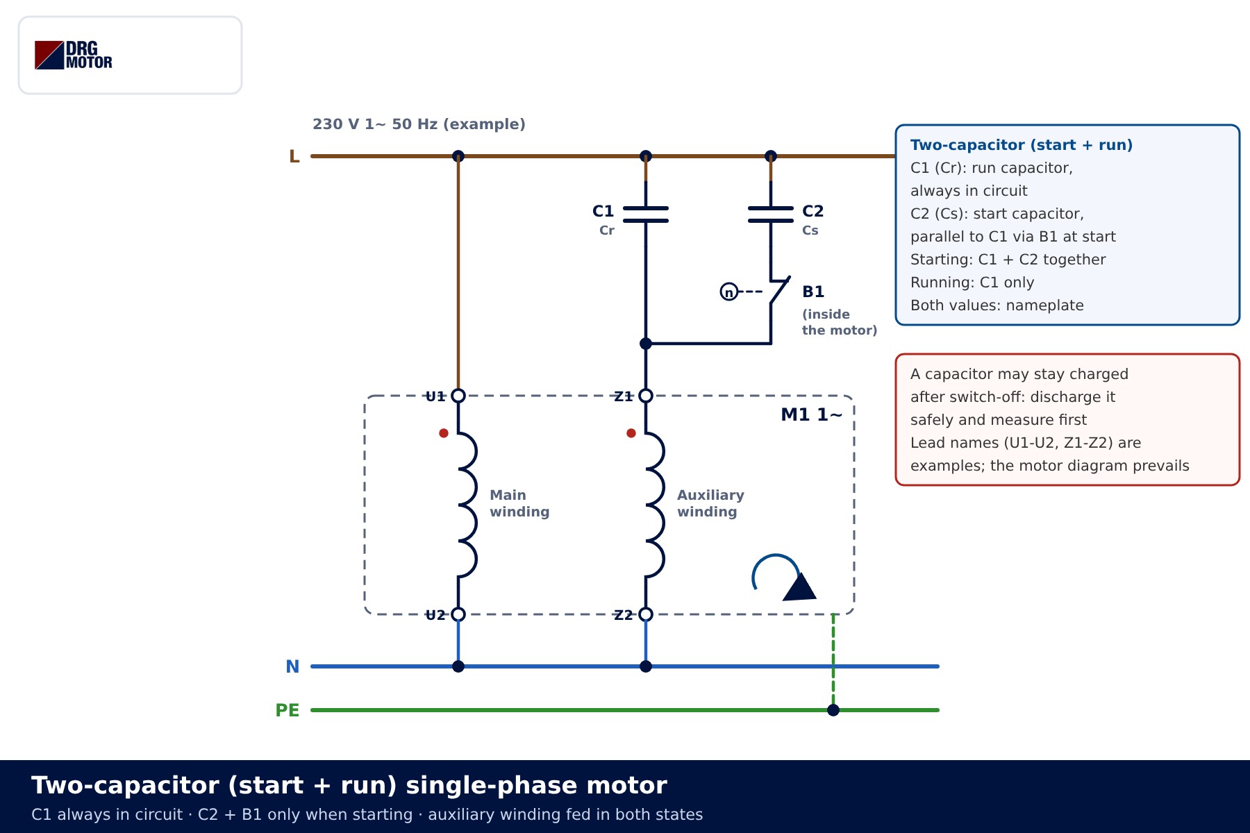
| Type | Capacitor | Centrifugal switch | Typical use |
|---|---|---|---|
| PSC | Run only (C1) | No | Fans, extractors, light loads |
| Capacitor-start | Start only (C2) | Yes | Pumps and compressors starting on load |
| Two-capacitor | Start + run | Yes | Machines needing high starting torque |
📄 Download Wiring Diagram PDF A4 printable PDF of the diagrams and tables (no sign-up)
Click to see current electric motor prices and order nowSEE PRICES →
How is the direction of rotation reversed?
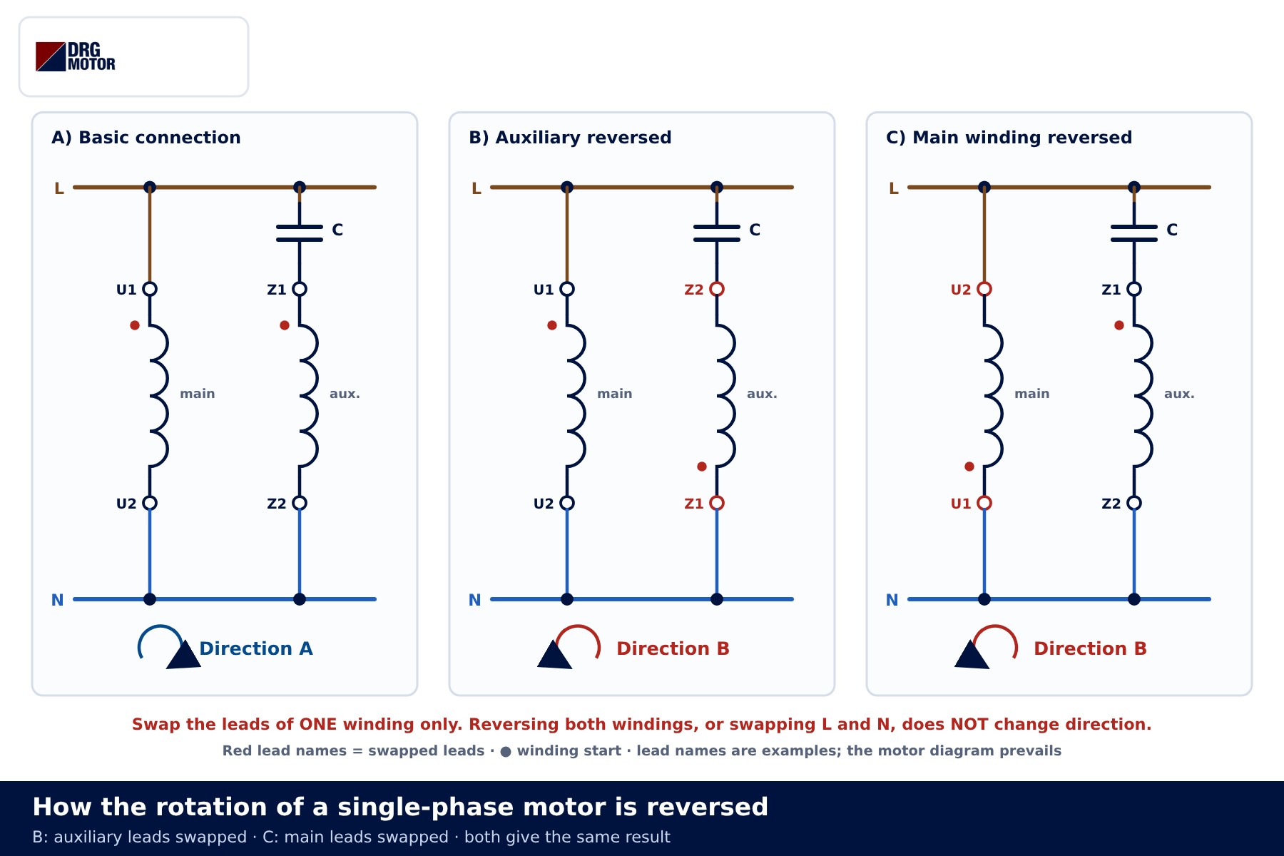
Direction depends on the order in which the two winding fields peak. Reverse the leads of one winding and that order flips, so the motor turns the other way. Which winding you reverse depends on the terminal layout: if the auxiliary leads are brought out, swap Z1 and Z2; if only the main leads are accessible, swap U1 and U2. Reversing both windings leaves the direction unchanged. For a comparison with phase swapping on three-phase machines, read how to reverse motor rotation.
Many motors select the direction with links in the terminal box. The drawing below is a generic example of the principle only: the second capacitor lead (C) is linked to Z1 in one case and to Z2 in the other, while L, N and the main winding stay put. The number of terminals, their order and the links differ between manufacturers; the motor’s own nameplate/terminal diagram always prevails. If there is no diagram, do not move links without identifying the leads by measurement.
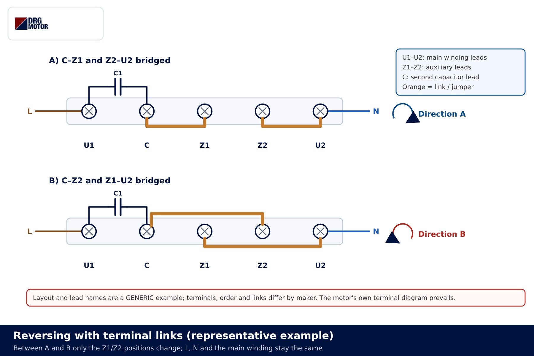
On motors with a centrifugal switch, reverse only from standstill. While the motor is running B1 is open and the auxiliary winding is out of circuit, so swapping its leads does nothing – the motor keeps turning the same way.
Forward/reverse with contactors
When direction changes often, two contactors replace the links. In the power circuit, K1 and K2 feed the main winding the same way in both directions; only the auxiliary winding changes. With K1 on, the capacitor goes to Z1 and Z2 to N; with K2 on, the connection is reversed. Q1 is a two-pole protective device sized from the rated current on the motor nameplate.
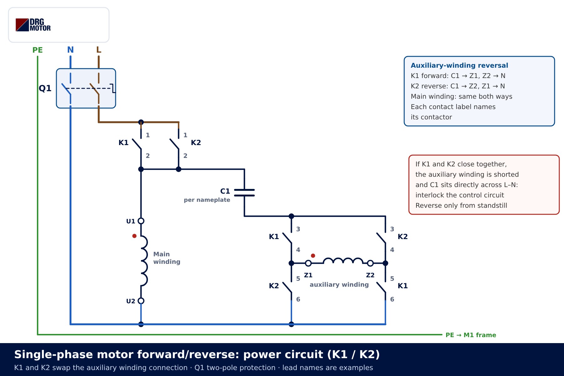
If both contactors closed at once the auxiliary winding would be short-circuited. The control circuit therefore gives each direction its own self-holding contact and an electrical interlock through the other contactor’s 21-22 NC contact – exactly as in three-phase forward/reverse contactor wiring.
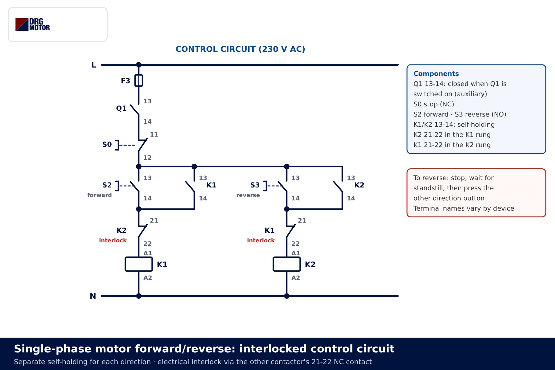
- Forward button (S2): the K1 coil is energised through K2 21-22 and K1 13-14 holds it. The capacitor connects to Z1 and the motor starts in direction A.
- Speed rises: on motors with a starting circuit, B1 opens and the main winding carries on alone.
- Reverse button (S3) pressed while running: K1 21-22 is open, so K2 cannot pick up – the interlock works.
- Stop button (S0): K1 drops out and the motor coasts to rest.
- Reverse button after standstill: K2 picks up, the capacitor connects to Z2 and the motor starts in direction B.
- Q1 trips: the Q1 13-14 auxiliary contact opens the control circuit and both contactors drop out; switching Q1 back on does not restart the motor by itself.
State table
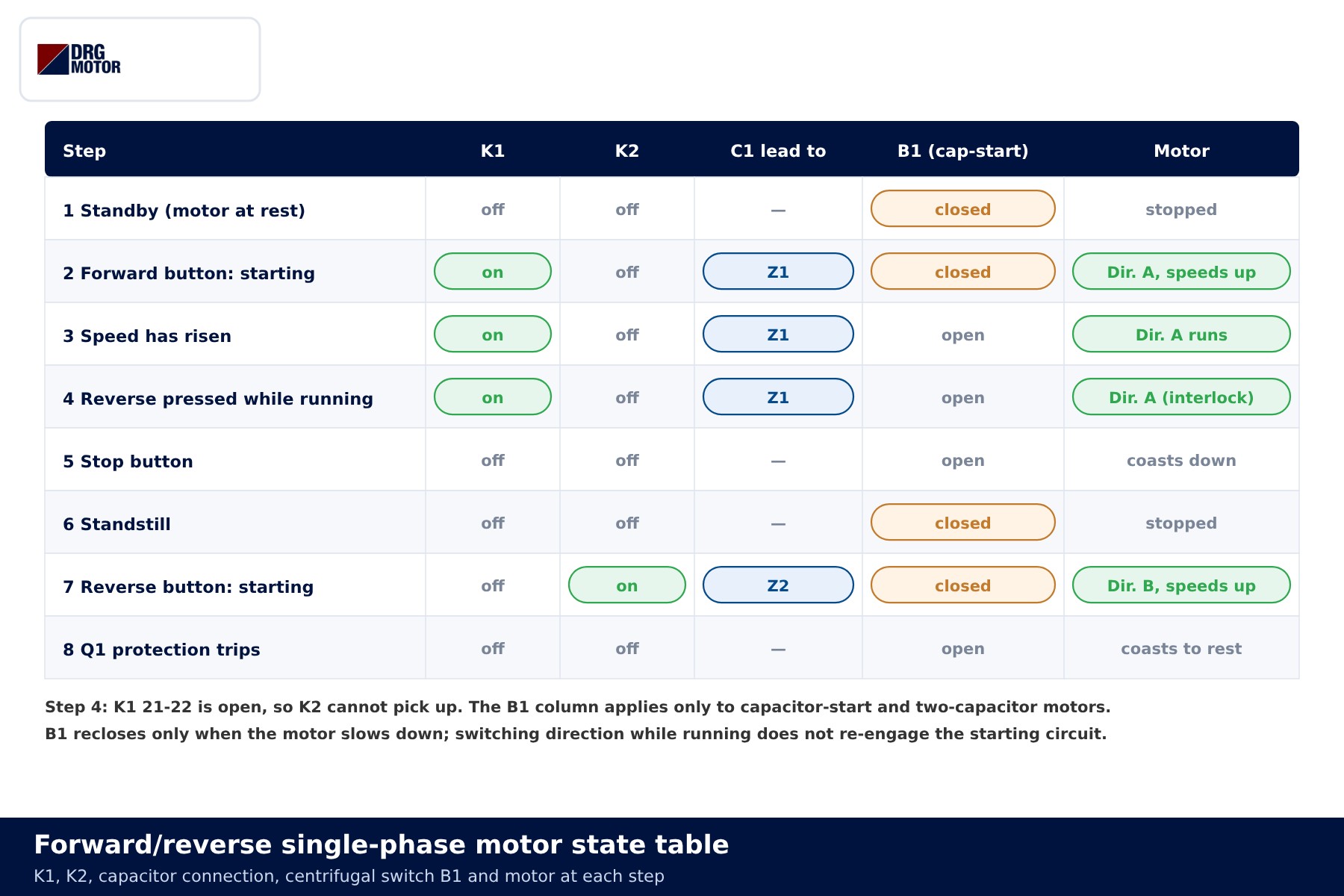
| State | K1 / K2 | Capacitor connected to | Motor |
|---|---|---|---|
| Standby | off / off | — | stopped |
| Forward start | on / off | Z1 | accelerates in direction A |
| Running forward, reverse pressed | on / off | Z1 | keeps direction A (interlock) |
| Stop, standstill | off / off | — | stopped |
| Reverse start | off / on | Z2 | accelerates in direction B |
| Q1 tripped | off / off | — | coasts to rest |
Capacitor type, value and discharge
Capacitance (µF), rated voltage and type are printed on the motor nameplate or on the capacitor itself. A replacement must match in type and value; making the capacitor bigger or smaller by guesswork upsets winding current, temperature and starting. We deliberately give no values here – the right value belongs to the motor’s own design.
- Run capacitor: usually a metallised film type, built to stay in circuit while the motor runs.
- Start capacitor: usually an AC electrolytic type, rated for short periods only; never use it in place of a run capacitor.
- Voltage: the capacitor’s rated voltage must not be lower than the value given on the nameplate.
Discharge warning: a capacitor can stay charged after the motor is switched off. Before touching the leads, discharge it with a suitable discharge device and confirm by measurement that no voltage remains. Shorting the leads with a screwdriver damages the capacitor and can produce a dangerous spark.
Common wiring mistakes
| Symptom | Likely cause |
|---|---|
| Motor hums but will not start; runs if pushed by hand | Faulty or disconnected capacitor, centrifugal switch not closing, or open auxiliary winding |
| Direction did not change | Both windings reversed together, or only L and N swapped |
| Capacitor bulged or got hot quickly | Start capacitor left in circuit (B1 stuck) or wrong type/voltage fitted |
| Motor runs hot | Capacitance different from the nameplate, low supply voltage or overload |
| Fuse blows when reversing | No interlock, K1 and K2 closed together; or direction changed while running |
| Motor keeps the same direction after reversing on the fly | B1 is open on a capacitor-start motor; reverse only from standstill |
A three-phase motor instead: using a 230 V input drive
Single-phase motors are not part of DRG’s standard range; DRG supplies three-phase asynchronous IEC motors. If your supply is single-phase and the load suits a three-phase motor, a frequency drive with 230 V single-phase input and three-phase output is an alternative. Because the drive delivers 3 × 230 V, a motor rated 230/400 V is connected in delta (Δ). Direction is changed by a drive command rather than rewiring, and there is no capacitor or centrifugal switch. Motor selection is covered in choosing a motor for a 220 V inverter, and the delta link-up in electric motor star-delta connection diagram.
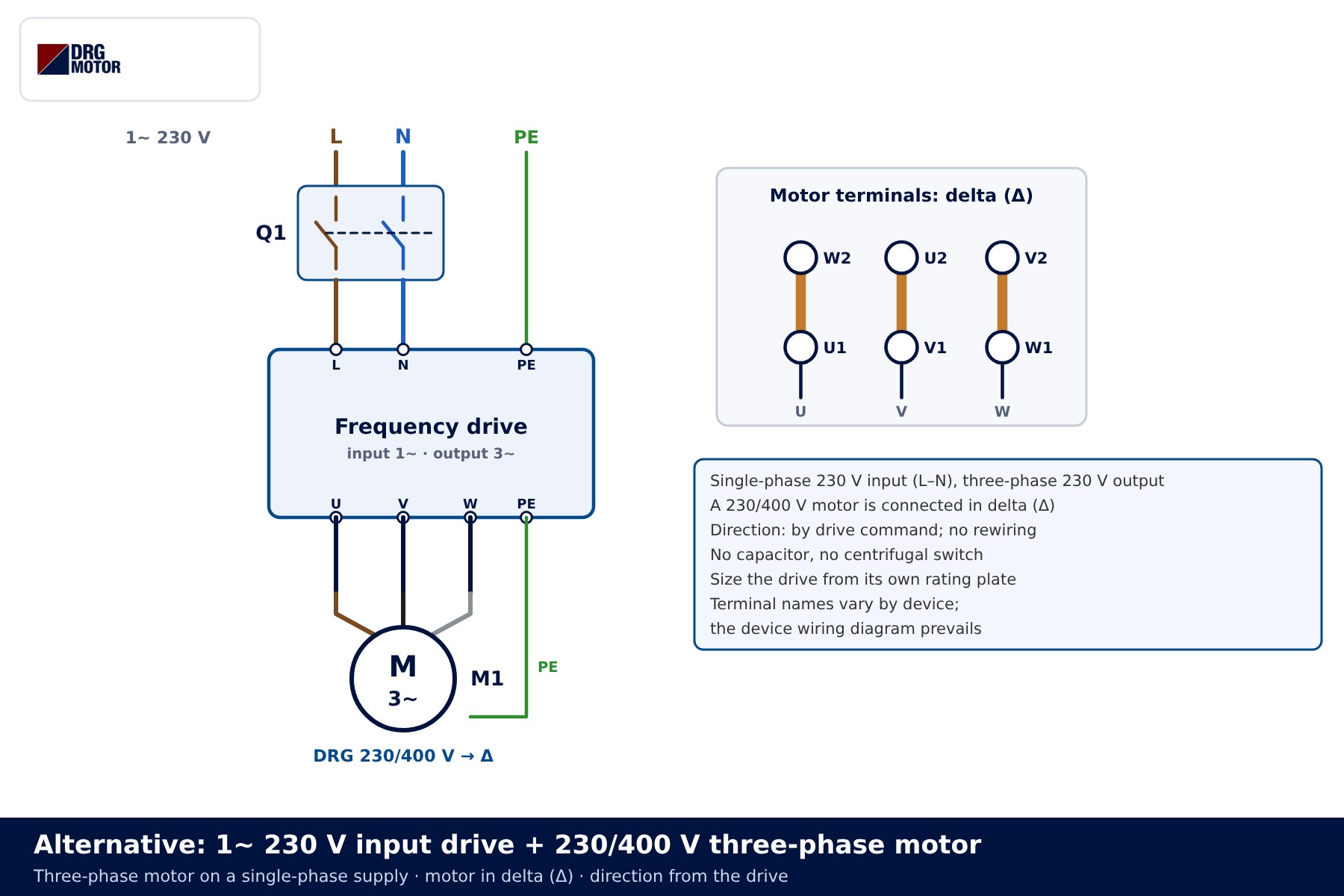
DRG does not sell drives; size the drive and its input current from the device manufacturer’s data, and note that terminal names vary by device. A three-phase motor can also run on single phase with a capacitor and no drive, but the power loss is significant – see can a three-phase motor run on single phase. Useful tools: the motor current chart, the electric motor calculator and the motor cable size calculator.
📄 Download Wiring Diagram PDF A4 printable PDF of the diagrams and tables (no sign-up)
Send a photo of your current motor nameplate and we will find the suitable DRG model together.Send on WhatsApp
DRG motors for use with a 230 V input drive
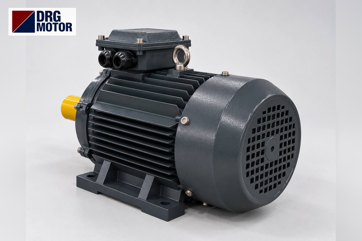
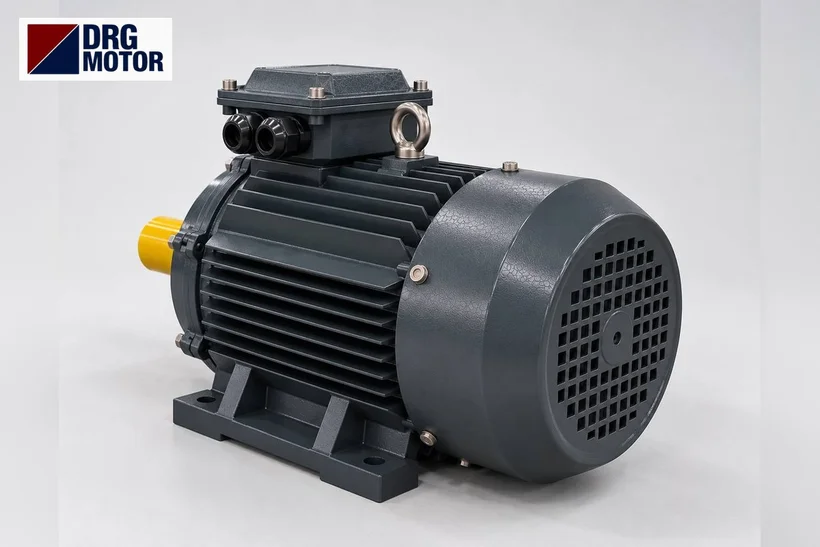
DRG Motor is a manufacturer, supplier and seller of electric motors. The 230/400 V aluminium-frame three-phase motors below, up to 3 kW, can be connected in delta and run from a drive with single-phase input. Single-phase motors, capacitors, contactors and drives are not sold by DRG. More options are listed on the three-phase asynchronous electric motors page and in the online store.
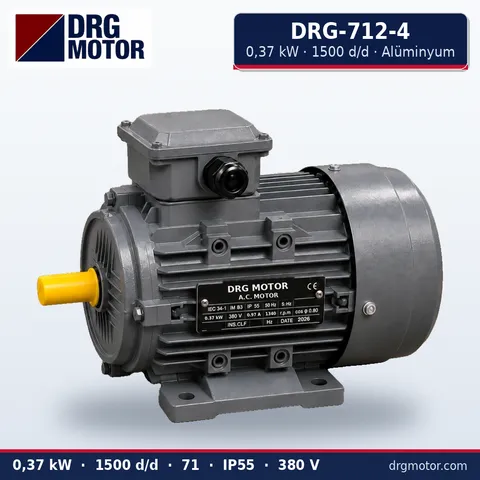
0.37 kW Three-Phase Motor 1500 rpm – DRG-712-4 Aluminium
- 0.37 kW · 1500 rpm (4 poles)
- Aluminium frame · IEC 71
- Mounting: B3 · B5 · B14 · B35
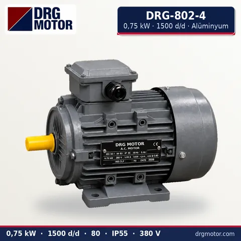
0.75 kW Three-Phase Motor 1500 rpm – DRG-802-4 Aluminium
- 0.75 kW · 1500 rpm (4 poles)
- Aluminium frame · IEC 80
- Mounting: B3 · B5 · B14 · B35
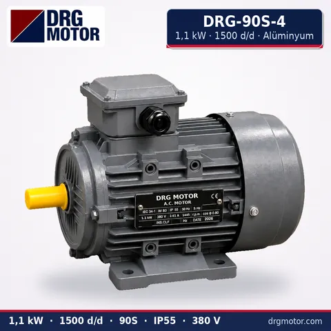
1.1 kW Three-Phase Motor 1500 rpm – DRG-90S-4 Aluminium
- 1.1 kW · 1500 rpm (4 poles)
- Aluminium frame · IEC 90S
- Mounting: B3 · B5 · B14 · B35
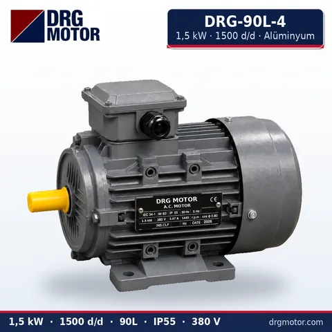
1.5 kW Three-Phase Motor 1500 rpm – DRG-90L-4 Aluminium
- 1.5 kW · 1500 rpm (4 poles)
- Aluminium frame · IEC 90L
- Mounting: B3 · B5 · B14 · B35
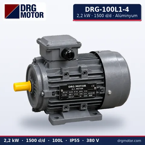
2.2 kW Three-Phase Motor 1500 rpm – DRG-100L1-4 Aluminium
- 2.2 kW · 1500 rpm (4 poles)
- Aluminium frame · IEC 100L
- Mounting: B3 · B5 · B14 · B35
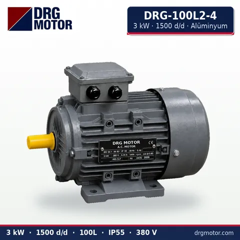
3 kW Three-Phase Motor 1500 rpm – DRG-100L2-4 Aluminium
- 3 kW · 1500 rpm (4 poles)
- Aluminium frame · IEC 100L
- Mounting: B3 · B5 · B14 · B35
Click to see current prices for these motors and order nowSEE PRICES →
Frequently asked questions
Does swapping L and N reverse a single-phase motor?
No. Swapping L and N reverses the current in both windings together, so their order stays the same. Only reversing the leads of one winding changes direction.
Should I reverse the main or the auxiliary winding?
Either gives the same result. In practice the auxiliary leads are usually swapped. The motor’s terminal diagram shows which leads are brought out and where the links go.
How do I find the capacitor value?
From the motor nameplate or the marking on the existing capacitor. If the plate is unreadable, ask the motor manufacturer or a qualified rewind shop; do not pick a value by guesswork.
Can I reverse the motor while it is running?
It is not recommended. Capacitor-start motors will not reverse while running, and on PSC motors plugging causes mechanical and electrical stress. Stop, wait for standstill, then select the other direction.
Does DRG offer single-phase motors?
No, single-phase motors are not in DRG’s standard range. For a three-phase solution on a single-phase supply, a 230 V input drive with a 230/400 V three-phase DRG motor is an alternative.





