 English
 Le français
 Türkçe




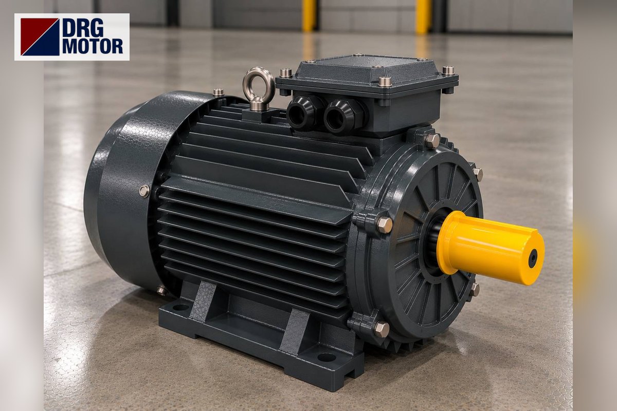

The usual way to control a drive’s (frequency inverter’s) speed from a PLC is to wire the PLC analogue output to the drive’s analogue input (AI1): the PLC produces a 0–10 V voltage or a 4–20 mA current, and the drive scales that signal to, for example, 0–50 Hz. Run and direction commands come from PLC digital outputs, and the drive’s fault status returns to a PLC input through a relay contact. For short, clean runs 0–10 V is enough; for long cables, noisy plant or when a broken wire must be detected, 4–20 mA is the better choice.
Safety notice: This content is for technical information only. Wiring, measurement and commissioning must be carried out by qualified electrical personnel, following lock-out and verification of de-energised state, and in line with the motor and device manufacturer's documentation.
Below we cover the power circuit, the two analogue wiring methods separately, the scaling calculation, the digital commands and when isolation is needed, each with a diagram. If the terms drive, converter and inverter are confusing, read frequency converter vs inverter first. Terminal names vary by device; AI1, GND, DI1 and COM in the diagrams are generic names, and the device’s own wiring diagram always prevails.
System layout: power circuit and control terminals
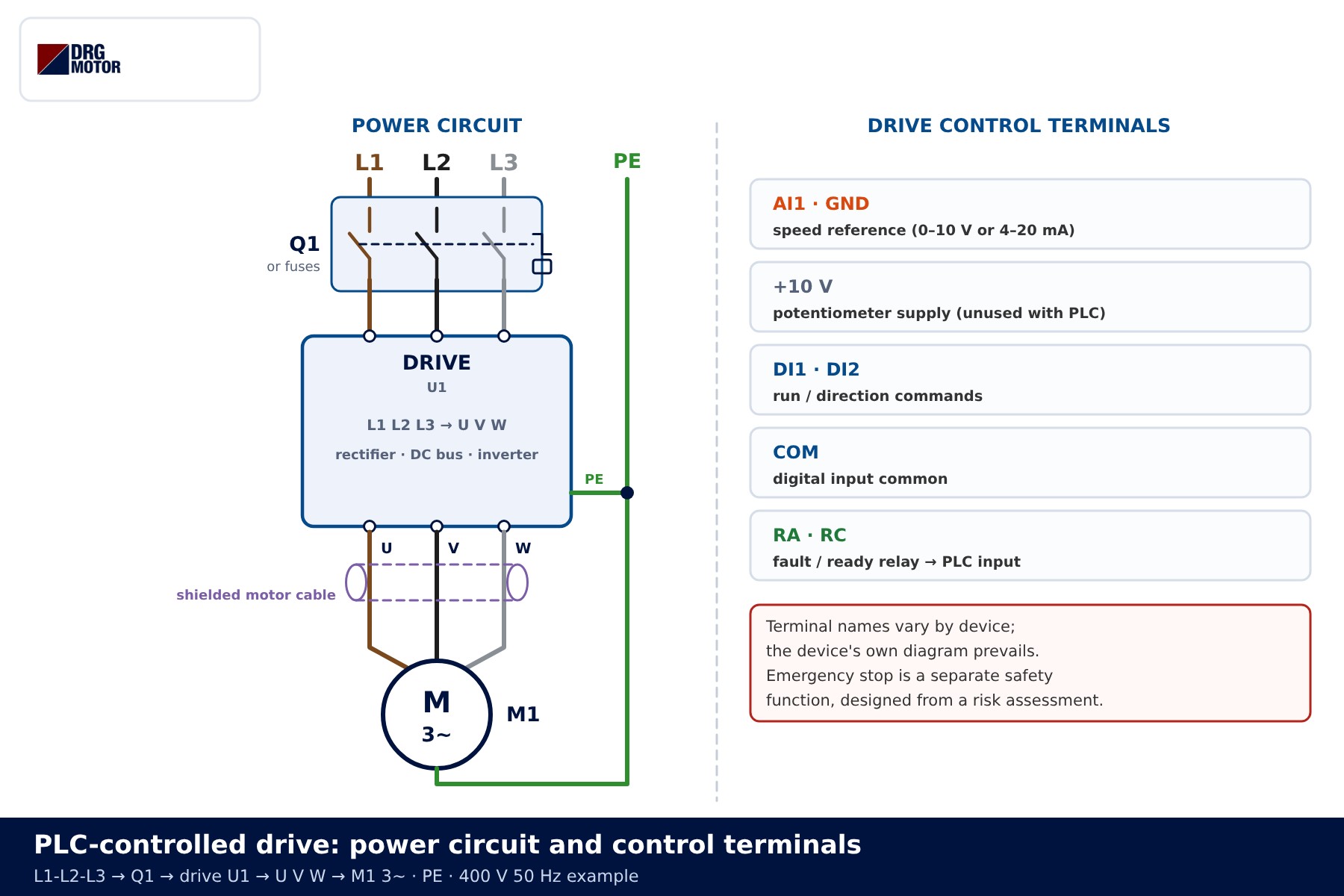
The power side is straightforward: L1-L2-L3 pass through a motor protection breaker (Q1) or fuses to the drive input, and the drive’s U-V-W outputs feed the motor through a shielded motor cable. No contactor is placed between drive and motor; the drive itself starts and stops the motor. The control terminals fall into five groups: analogue input (AI1 and GND), the +10 V potentiometer supply, digital inputs (DI1, DI2) with their common (COM), and a fault/ready relay (RA-RC).
| Component | Terminals (generic) | Function |
|---|---|---|
| Q1 motor protection breaker or fuses | L1-L2-L3 | Protects the drive supply line |
| U1 drive (inverter) | L1 L2 L3 / U V W / PE | Sets motor frequency and voltage |
| PLC analogue output | AO+ and AO 0 V | Produces the 0–10 V or 4–20 mA speed reference |
| Drive analogue input | AI1 and GND | Reads the reference; type set by switch and/or parameter |
| PLC digital outputs | DO0, DO1 | Run and direction commands |
| Drive digital inputs | DI1, DI2, COM | Receive the commands |
| Drive relay | RA-RC (NO) | Returns ready/fault status to a PLC input (DI0) |
| M1 motor | U1 V1 W1 + PE | Three-phase induction motor; terminal link to suit the drive output voltage |
The +10 V potentiometer terminal stays unused when a PLC provides the reference. Connecting both the PLC signal and a potentiometer to the same input simply ties two sources together. The motor terminal connection is chosen from the drive output voltage; the star-delta connection diagram and motor selection for a 220 V input inverter explain this point.
0–10 V voltage wiring
Voltage wiring needs two conductors: PLC AO+ to drive AI1, and the PLC analogue 0 V (often marked M or COM) to drive GND. The second wire is frequently forgotten or skipped on the assumption that “both are earthed anyway”. The drive, however, measures the difference between AI1 and GND; without a common 0 V reference the reading floats and the speed drifts on its own.
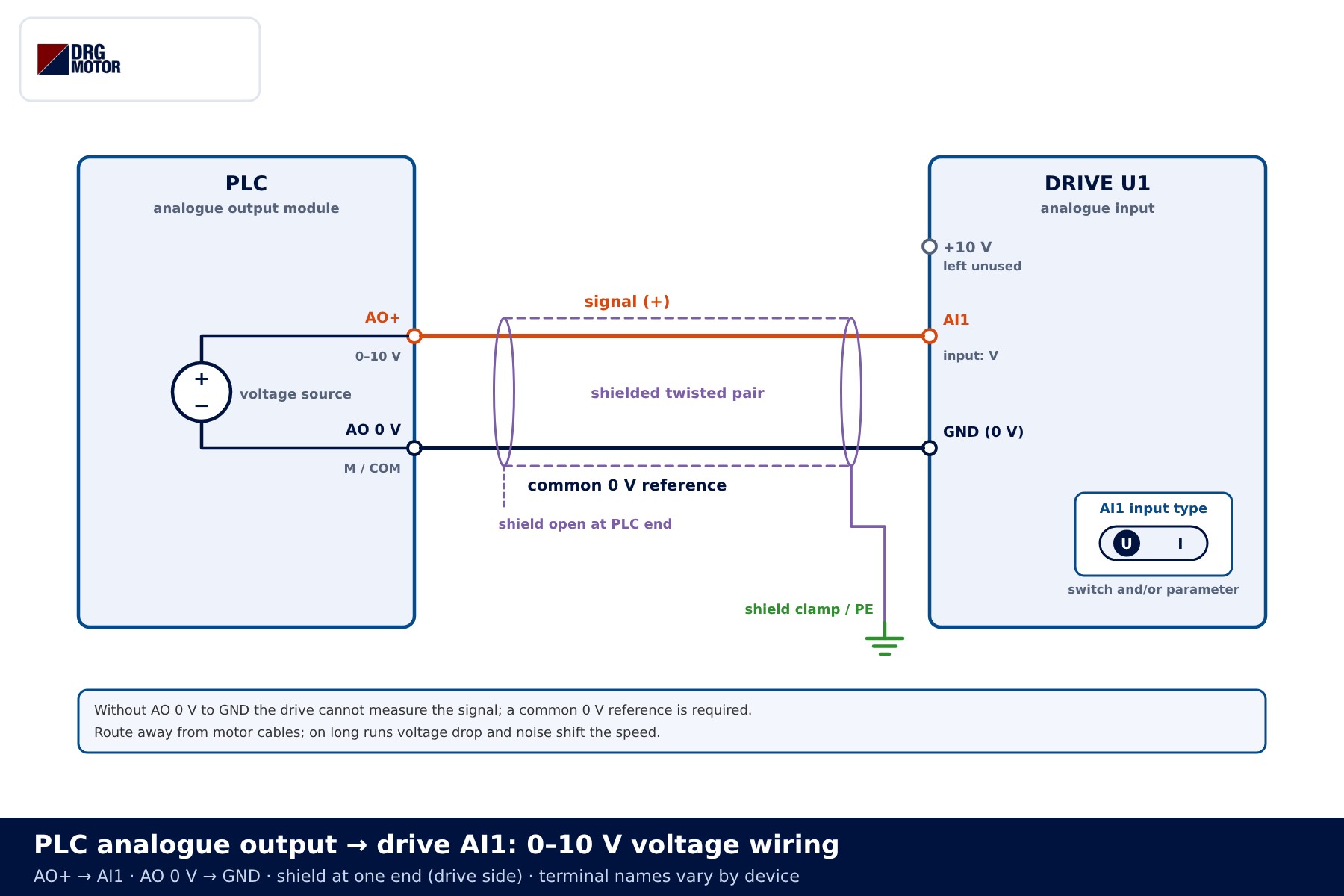
- Cable: shielded twisted pair, kept out of the motor cable tray; where crossing is unavoidable, cross at right angles.
- Shield: normally bonded at one end only, to the shield clamp/PE at the drive; the other end is left open. Bond both ends only where the panels share a good equipotential connection and the device documentation recommends it.
- Weak point: a voltage signal is affected by line resistance and noise. A few hundred millivolts of error on a long run means the speed moves by a few hertz. If the cable breaks, the drive reads 0 V and ramps to zero speed – it cannot tell this from a genuine zero command.
📄 Download Wiring Diagram PDF A4 printable PDF of the diagrams and tables (no sign-up)
Click to see current electric motor prices and order nowSEE PRICES →
4–20 mA current wiring
Current wiring also uses two conductors, but works differently. The PLC output is a current source: current leaves AO+, flows through the internal load resistor of drive input AI1 and returns via GND to the PLC 0 V. In this closed loop the cable resistance does not change the current, as long as the source has enough compliance. That is why 4–20 mA is more stable over long distances and in electrically noisy areas.
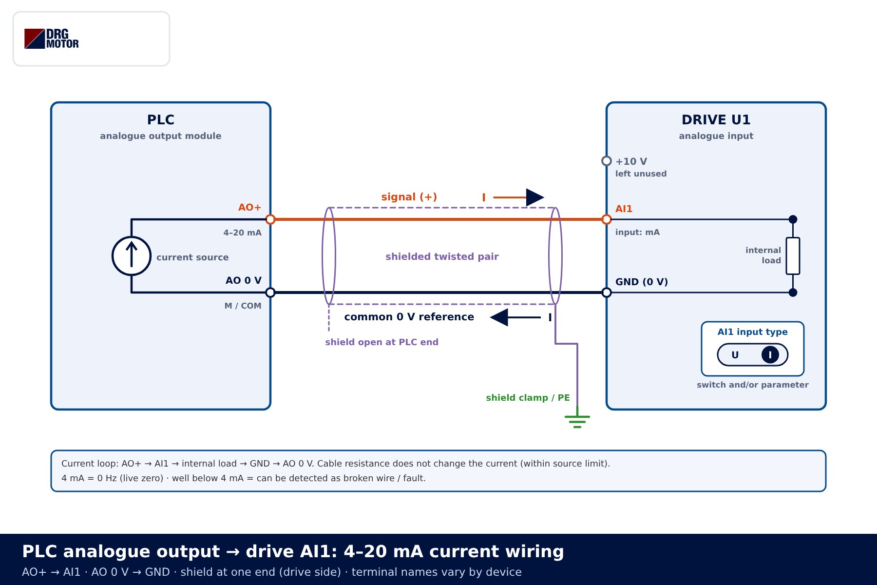
The second benefit is the “live zero”. Even at 0 Hz, 4 mA flows in the loop. If the current falls clearly below 4 mA, the message is not “stop” but “something has broken”: a cut cable, a loose terminal or a failed PLC module. Many drives can treat this as reference loss and trip, switch to a preset speed or stop; the reaction and the detection threshold are set by drive parameters. Choose the reaction that is safe for the machine.
Selecting the input type: switch and parameter
On most drives the same AI1 terminal can read either voltage or current. Which one it reads is set by an on-board switch or jumper (U/I) and/or a parameter. If the switch is not in the “I” position, a 4–20 mA signal is read as voltage and the speed either does not change or moves only within a narrow band. Before commissioning, check that switch and parameter point to the same type, and choose values from the device documentation.
Signal-to-frequency scaling and intermediate values
With linear scaling, the lower end of the signal corresponds to the lowest frequency and the upper end to the highest. The figure shows the 0–50 Hz scale for both signal types with sample points.
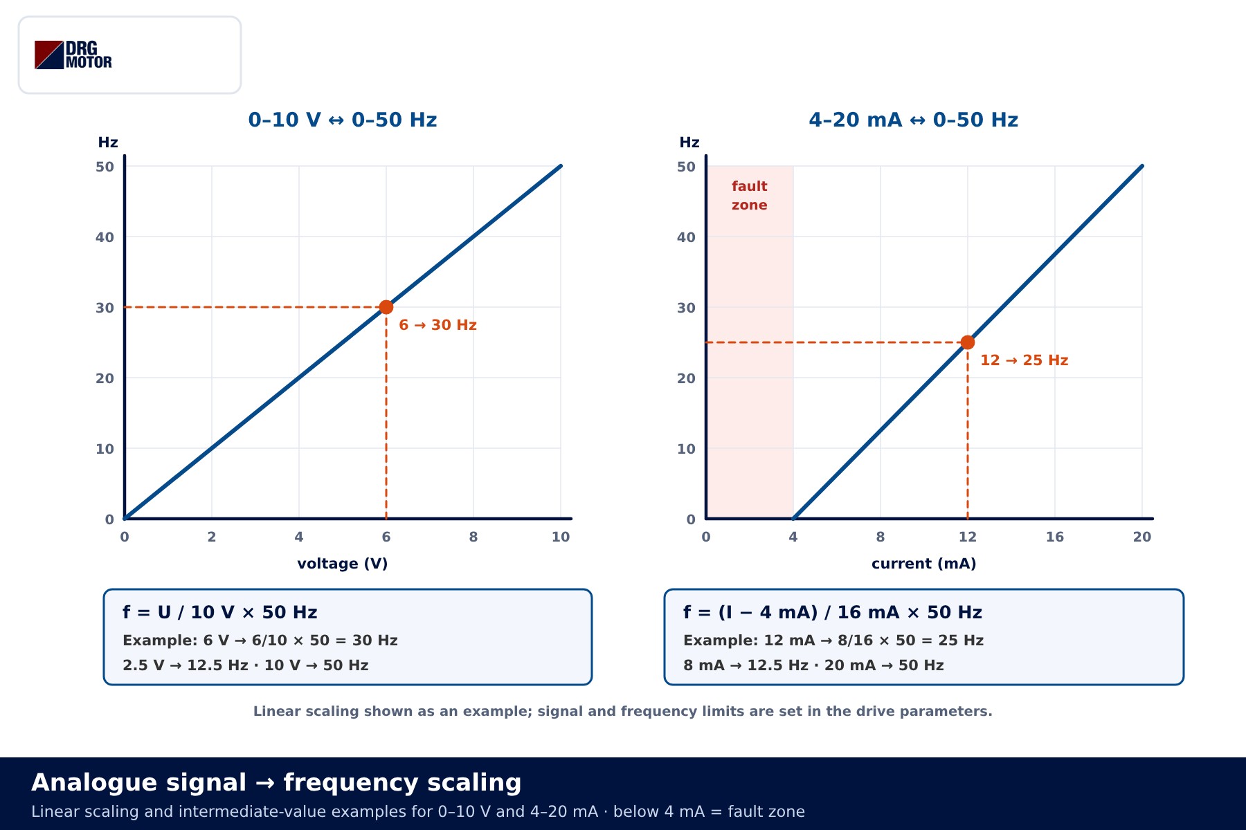
- 0–10 V: f = U / 10 V × 50 Hz. Example: 6 V → 6/10 × 50 = 30 Hz.
- 4–20 mA: f = (I − 4 mA) / 16 mA × 50 Hz. Example: 12 mA → 8/16 × 50 = 25 Hz. The divisor is 16, not 20, because the span starts at 4.
- Reverse (PLC side): for 35 Hz send 35/50 × 10 = 7 V on 0–10 V, or 4 + 35/50 × 16 = 15.2 mA on 4–20 mA.
| Target frequency | 0–10 V signal | 4–20 mA signal |
|---|---|---|
| 0 Hz | 0 V | 4 mA |
| 12.5 Hz | 2.5 V | 8 mA |
| 25 Hz | 5 V | 12 mA |
| 30 Hz | 6 V | 13.6 mA |
| 50 Hz | 10 V | 20 mA |
This table is an example only. On the drive, the signal limits, the matching frequencies, minimum speed and ramp times are parameters; set them during commissioning from the motor nameplate and the application. On the PLC side the analogue output works in raw counts, and conversion to engineering units is done in the PLC program. The motor current chart helps check nameplate current. If you plan to run above 50 Hz or carry load at low speed for long periods, see insulation and forced cooling for VFD motors.
Digital commands and the fault relay back to the PLC
The analogue signal sets the speed, but the drive also needs a run command. In a typical layout PLC output DO0 drives DI1 (run/forward) and DO1 drives DI2 (reverse); the PLC 0 V goes to the drive COM. Drive digital inputs may work in PNP (source) or NPN (sink) logic; this must match the PLC output type and is changed, depending on the device, by a switch, a jumper or a parameter.
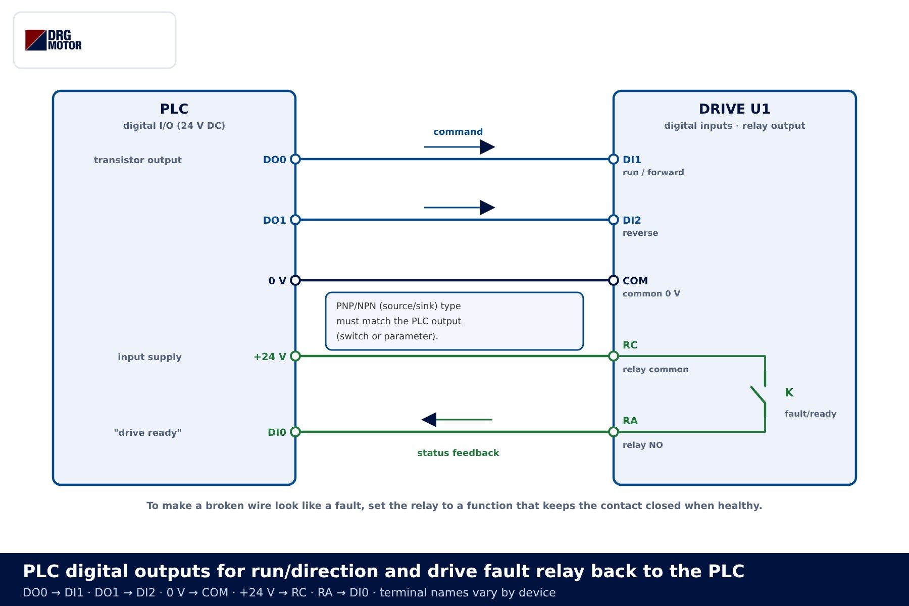
Feedback uses the drive relay: PLC +24 V to RC, and RA to a PLC input (DI0). If the relay function is set to “ready/no fault”, the contact is closed while healthy, and the input drops on a fault or a broken wire. The PLC therefore sees a cut cable as a fault too. Interlock the two direction outputs in the PLC program so they are never on together.
| Step | DO0 / DO1 | Analogue signal | Motor |
|---|---|---|---|
| 1 Standby, drive ready | 0 / 0 | any | stopped; DI0 = 1 (ready) |
| 2 Run forward | 1 / 0 | 5 V or 12 mA | ramps up to 25 Hz |
| 3 Speed change | 1 / 0 | 8 V or 16.8 mA | ramps up to 40 Hz |
| 4 Run command removed | 0 / 0 | unchanged | ramps down and stops |
| 5 Reverse | 1 / 1 (setting) | 5 V or 12 mA | 25 Hz in reverse |
| 6 4–20 mA wire broken | 1 / 0 | ≈ 0 mA | reference-loss reaction (per parameter) |
| 7 Drive fault | 1 / 0 | any | stops; DI0 = 0, PLC raises an alarm |
In step 5, the input combination for reverse depends on the drive’s command mode. An emergency stop is not added as “one more digital input”; it is a separate safety function designed from the machine’s risk assessment.
When is galvanic isolation needed?
When the PLC and drive sit in different panels with different earth points, a small potential difference can exist between the two 0 V sides. Because the analogue 0 V wire joins them, a balancing current flows through it, showing up as offset or ripple on the signal. A galvanic isolator (signal isolator) or an isolated analogue module carries the signal while breaking the conductive path between both sides.
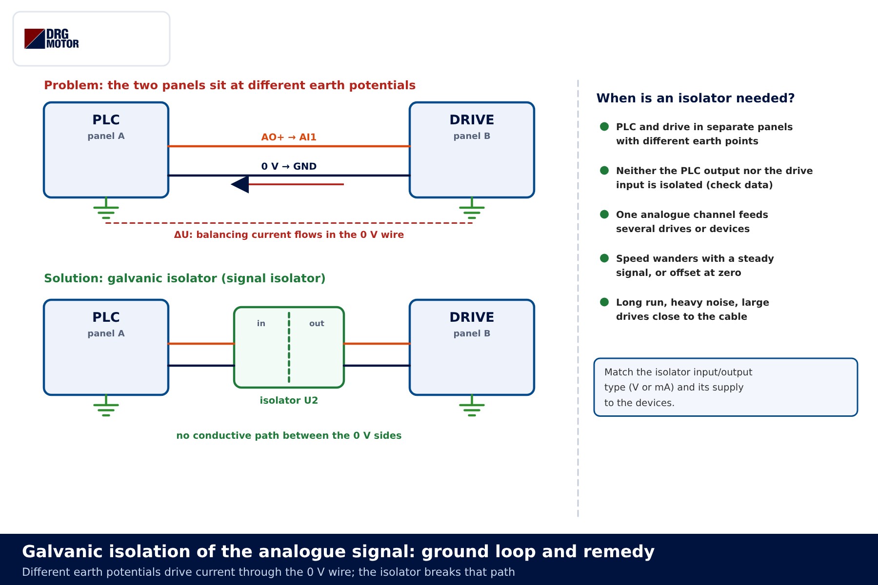
The checklist is in the figure. Inside one panel with a short, correctly routed cable it is usually unnecessary. Choose the isolator’s input and output type (V or mA) and its supply to suit the connected devices.
Common wiring mistakes
| Symptom | Likely cause |
|---|---|
| No response to the speed reference; motor stays at minimum speed | PLC voltage output (0–10 V) wired to a current input, or wrong input-type switch/parameter |
| Speed fluctuates with a steady signal | No common 0 V, no shield or shield bonded at both ends, cable in the motor cable tray |
| On 4–20 mA the motor turns even at minimum signal | Scaling left at 0–20 mA; lower limit not set to 4 mA |
| No alarm when the cable breaks | Reference-loss detection disabled, or 0–10 V in use (a break looks like 0 V) |
| Run command sent but the drive does not start | PNP/NPN logic does not match the PLC output; COM not connected |
| PLC analogue module damaged | Drive +10 V reference wired to the PLC output; two sources tied together |
| PLC does not see drive faults | Wrong relay function selected or NC/NO terminals mixed up |
Motor cable size and length also affect the drive output; the motor cable size calculator gives a starting point. If the drive trips on overvoltage during fast stops, see dynamic braking and braking resistors on inverters.
Selection examples
- PLC and drive in the same panel, 2–3 m cable, fan: 0–10 V is enough. A shielded cable and a common 0 V are adequate; an isolator is usually not needed.
- Pump station with the PLC in a control room and the drive 60–80 m away: 4–20 mA with a “stop + alarm” reaction on reference loss. If the panels use different earth points, add a galvanic isolator.
📄 Download Wiring Diagram PDF A4 printable PDF of the diagrams and tables (no sign-up)
Send a photo of your current motor nameplate and we will find the suitable DRG model together.Send on WhatsApp
DRG motors for drive speed control
DRG Motor is an electric motor manufacturer, supplier and seller. The three-phase IEC motors below fall in the power range commonly used in drive-controlled fan, pump and conveyor applications. PLCs, drives (inverters) and signal isolators are not sold by DRG; please contact your panel component supplier or the device manufacturer for these. More power and speed options are listed under three-phase asynchronous electric motors and in the online store.
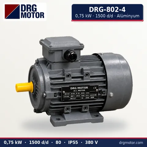
0.75 kW Three-Phase Motor 1500 rpm – DRG-802-4 Aluminium
- 0.75 kW · 1500 rpm (4 poles)
- Aluminium frame · IEC 80
- Mounting: B3 · B5 · B14 · B35
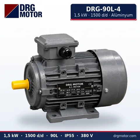
1.5 kW Three-Phase Motor 1500 rpm – DRG-90L-4 Aluminium
- 1.5 kW · 1500 rpm (4 poles)
- Aluminium frame · IEC 90L
- Mounting: B3 · B5 · B14 · B35
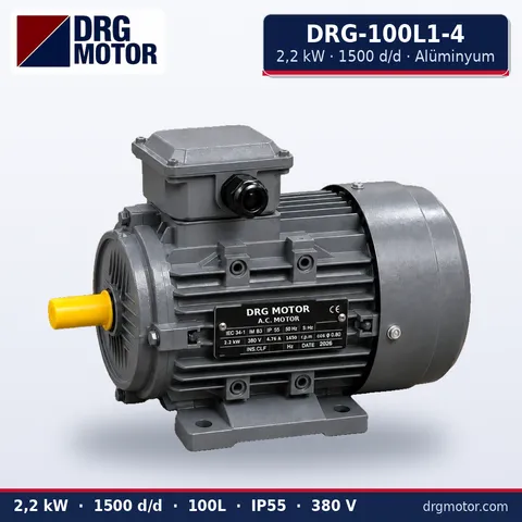
2.2 kW Three-Phase Motor 1500 rpm – DRG-100L1-4 Aluminium
- 2.2 kW · 1500 rpm (4 poles)
- Aluminium frame · IEC 100L
- Mounting: B3 · B5 · B14 · B35
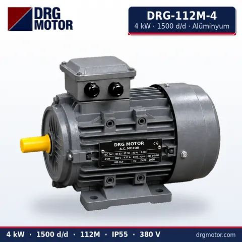
4 kW Three-Phase Motor 1500 rpm – DRG-112M-4 Aluminium
- 4 kW · 1500 rpm (4 poles)
- Aluminium frame · IEC 112M
- Mounting: B3 · B5 · B14 · B35
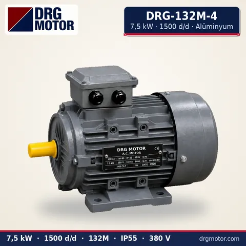
7.5 kW Three-Phase Motor 1500 rpm – DRG-132M-4 Aluminium
- 7.5 kW · 1500 rpm (4 poles)
- Aluminium frame · IEC 132M
- Mounting: B3 · B5 · B14 · B35
Click to see current prices for these motors and order nowSEE PRICES →
Frequently asked questions
Should I use 0–10 V or 4–20 mA?
For a short run inside one panel, 0–10 V is enough. Choose 4–20 mA for long cables, noisy environments or when a broken wire must be detected. Check which types the PLC output module and the drive input support.
Is the analogue 0 V wire really necessary?
Yes. The drive measures the difference between AI1 and GND. Without a common 0 V reference the measurement floats, and the speed either drifts or does not respond.
Should the shield be bonded at both ends?
On analogue signal cables it is normally bonded at one end, on the drive side. Bonding both ends is possible where the panels have a good equipotential connection; follow the device documentation.
What does the drive do when the signal drops below 4 mA?
With detection enabled the drive treats it as reference loss: it may trip and stop, switch to a preset speed or keep the last speed. Threshold and reaction are parameters; choose what is safe for the machine.





