English
 Türkçe

A motor driven by a variable frequency drive (VFD) lives in a very different world from one connected straight to the mains. The voltage is no longer a clean sine wave but a chopped waveform built from high-frequency pulses; the cooling fan usually sits on the same shaft as the rotor, so airflow drops sharply at low speed; and the winding insulation faces voltage spikes it would never see in a standard line application. For this reason, sound VFD motor selection depends not only on power and speed but just as much on insulation class and cooling method. At DRG Motor we evaluate these two decisive factors together for every inverter-driven application, from project survey to delivery, and ship the right motor fast from stock.
Why an Inverter-Driven Motor Works Harder
A VFD creates its output voltage through pulse width modulation (PWM). The rise time of these pulses is in the nanosecond range, and as each pulse travels along the motor cable, reflections can drive the voltage at the winding terminals up to twice the nominal value. Long motor cables make this effect worse. The first few turns of the winding therefore endure a voltage stress they would never face on the mains. A standard motor can suffer premature winding failure under these conditions, which is exactly why insulation for an inverter-fed motor must be specified to withstand that stress from the start.
The same harshness shows up on the cooling side. A motor running at fixed speed on the mains always draws the same airflow from its fan and behaves predictably in thermal terms. With a VFD, the operating point shifts throughout the process; the motor may run at full speed for one hour and at half speed the next. This variability means both the insulation and the cooling have to be sized for the worst-case operating point. Designing only for rated speed overlooks the low-speed region where the motor is in fact under the most strain. A sound configuration is built around the real duty profile in the field, not the nameplate figure on paper.

Insulation Class and Inverter-Grade Windings
Class F insulation (155 °C) is the common baseline, and when a motor runs at Class B temperature rise it keeps a healthy thermal reserve. In an inverter application, two extra measures matter most. The first is winding the motor with inverter-grade enamelled wire developed to resist high-voltage pulses and partial discharge. The second is limiting terminal voltage spikes by accounting for cable length and, where needed, adding output filters (dU/dt or sine-wave filters). Tell us your inverter brand, cable length and switching frequency, and we will recommend the right winding and filter combination for your case.
On the efficiency side, IE3 motors paired with a VFD both lower energy consumption and reduce the thermal load, because they generate fewer losses. Combining a high-efficiency frame with an inverter-grade winding builds the most robust foundation for long life and low running cost. From our broad power range of IE3 electric motors we can select the frame that fits your application and offer it together with an inverter-grade winding option.
The Real Point of Forced Cooling: Variable Speed
On a standard motor the cooling fan is fitted to the end of the shaft and turns at the same speed as the rotor. At full speed this provides enough airflow, but when a VFD runs the motor at low speed for long periods, the fan slows down too and cooling capacity drops noticeably. Even if torque stays constant, the windings keep generating the same heat. Low speed combined with high torque is the most demanding operating point for self-cooled motors, and this is exactly where forced cooling earns its place.
Forced cooling means a separate cooling fan with its own independent electrical supply, decoupled from the motor shaft. Whether the motor turns at 5 Hz or 50 Hz, the fan keeps producing steady, full airflow. The result is a thermally safe drive that can deliver constant torque across a wide speed range. On conveyors, extruders, mixers, filling lines and similar constant-torque applications, this feature is often not a preference but a requirement.

Which Applications Truly Need Forced Cooling?
Not every inverter-driven motor needs forced cooling. To make the right call you have to know the torque-speed profile of the application. In practice, an independent fan is strongly recommended in these cases:
- Processes where the motor runs loaded for long periods well below rated speed (for example at 30% and lower).
- Constant-torque mechanisms where torque does not fall as speed drops (conveyors, hoists, mixers, extruders).
- Drives that dwell at low speed for long periods due to frequent start-stop cycles or positioning.
- Plants with high ambient temperature where self-cooling is no longer sufficient.
By contrast, in variable-torque applications such as pumps and fans, where torque drops quickly as speed falls, the motor already produces little heat at low speed, so self-cooling is usually enough. To pin down which category you fall into, just share your process data with us and we will determine the right cooling method together.
Treating Insulation and Cooling as One Problem
Insulation and cooling may look like two independent line items, but they are really two sides of the same problem: keeping the winding temperature under control. Inverter-grade insulation protects the winding against voltage pulses, while forced cooling carries away the heat that builds up at low speed and extends the life of that insulation. When they are not considered together, you end up with a correct but incomplete measure. A motor with an inverter-compatible winding but only self-cooling, for instance, can still overheat at very low speed under constant torque. That is why we put both items on the same table at the quotation stage.
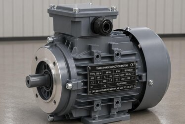
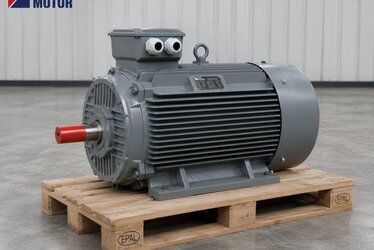
As a reference for choosing the right power class, mid-range models such as the 11 kw elektrik motoru should, when run on a VFD, be planned with an inverter-grade winding and a suitable cooling method. At lower powers, where mounting type also matters, foot-flange bodies like the 4 kw 4 kutup b35 motor stand out in inverter-driven conveyor and dosing applications. Whatever the rating, the selection logic is the same: match insulation and cooling to the real operating profile of the application.
Bearing Currents and Guarding Against Silent Damage
One topic that is easy to overlook on inverter-driven motors, yet costly over time, is bearing currents. PWM voltage creates small voltage differences between the shaft and the frame; when these discharge through the bearings, micro-arcing occurs between the balls and the race, gradually causing fluting on the bearing surface. The symptom usually appears first as noise and then as an unexpected bearing failure. To reduce this risk, especially in high-power applications with long cables, we recommend an insulated bearing, a shaft grounding ring, or a correct cabling and grounding scheme. Because the right measure depends on motor power and inverter installation, we assess this too at the quotation stage according to your application.
Thermal Protection and Feedback Options
In an inverter drive it is wise to safeguard winding temperature not only by design but by measurement. We can therefore fit our motors with PTC thermistors or PT100 temperature sensors; wired to the inverter protection input, these stop the motor in case of overheating. For applications that need closed-loop speed control at low speed, we can add an encoder, and where required we plan the independent fan supply and its electrical interface to suit your panel. The goal is for the motor to stay safe, both thermally and in terms of control, at its real operating point in the field.
None of this hardware is needed all at once; the right package is set by how critical the application is and by its operating profile. Full sensor instrumentation and forced cooling make sense in a continuous production line where downtime is very expensive, while a simpler protection scheme can be enough on a drive that runs only occasionally. We work out that balance with you so the solution is both safe and within budget.
What to Share Before We Quote
To complete your VFD motor selection quickly and correctly, a few details are enough: the type and torque characteristic of the driven machine (constant or variable), the operating speed range (lowest and highest frequency), daily running hours, ambient temperature, the inverter brand and motor cable length, plus the mounting type (B3 foot, B5/B35 flange). With this information we combine insulation class, winding type, cooling method and the necessary sensors into a single offer. Because the net price depends on power, cooling option, sensor package and lead time, the most reliable path is to request a quotation tailored to your application.
The Right Match Means Longer Life
Success in an inverter-driven motor never rests on a single component; it depends on the harmony of insulation, cooling, protection and the correct power class. Getting that match right is the difference between years of trouble-free service in the field and a rewind within a couple of years. At DRG Motor we supply inverter-grade insulated, optionally force-cooled and thermally protected solutions for your VFD applications, fast and from stock. Send us your application data, let us determine the best motor for the field together, and we will prepare your quotation the same day.