English
 Le français
 Türkçe




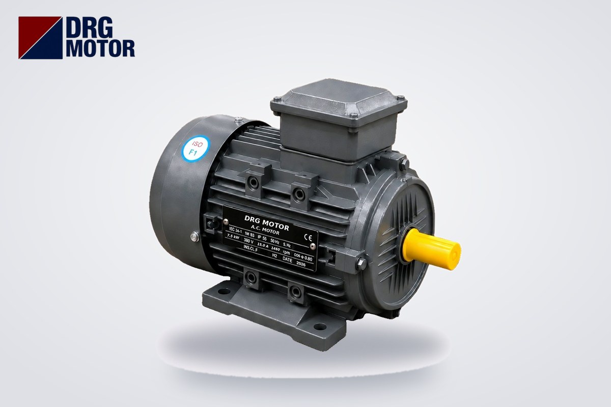

In practice there is no difference between a frequency converter and an inverter: in the field, "frequency converter", "frequency inverter", "inverter", "drive" and "speed controller" all refer to the same box, and all of them adjust the speed of a three-phase induction motor by changing the frequency and voltage they supply. Technically, however, the inverter is only one stage of the device: the power-switch section that turns DC voltage back into AC with adjustable frequency. The frequency converter (drive) is all three stages together: the rectifier that converts the mains to DC, the DC bus, and the inverter at the output.
This distinction matters when buying or reading a catalogue: a device sold as an "inverter" that is fed from the mains also contains a rectifier and is a complete frequency converter. Solar inverters and UPS inverters, on the other hand, are not designed to drive motors; they produce a fixed 50 Hz from DC. On the motor side, what counts is not the device's name but its output current, its control method and the motor's compatibility with the drive. You can browse three-phase motors for drive operation by power, speed and frame on Buy Electric Motors Online.
What is inside a frequency converter? Rectifier, DC bus and inverter
The power circuit of a frequency converter works in this order:
- Rectifier: Converts the three mains phases to DC with a diode bridge. On a 380 V supply the DC bus voltage is about 1.35 × 380 ≈ 513 V; on a 400 V supply about 540 V.
- DC bus: Capacitors smooth this voltage and store energy. The braking resistor and the DC choke connect to this section.
- Inverter: Power switches called IGBTs switch the DC voltage on and off at kilohertz rates (pulse width modulation, PWM). By varying the pulse widths, a near-sinusoidal current at the required frequency and voltage is created in the motor winding.
The control board manages these three stages; this is where you set motor parameters, ramp times, current limit and protections. Small drives with single-phase 230 V input have the same structure; only the rectifier is single-phase and the output is 3 × 230 V. The word "inverter" became the name of the whole device because this output stage is its most characteristic part.
Terminology table
| Term | Technical meaning | Use in the field | Does it drive a motor? |
|---|---|---|---|
| Inverter | DC → variable-frequency AC stage | For the whole device | Yes, if it is a mains-fed drive |
| Frequency converter / frequency inverter | Rectifier + DC bus + inverter | Same device | Yes |
| Motor drive, AC drive, VFD | Complete system including control | Same device | Yes |
| Solar / UPS inverter | DC → fixed 50 Hz AC | Energy systems | Not for speed control |
| Soft starter | Ramps up voltage at start with thyristors | Often confused | Start/stop only; no speed control |
How do motor speed and voltage change with frequency?
The synchronous speed of an induction motor is n = 120 × f / p (f: frequency, p: number of poles). A 4-pole motor runs at a synchronous speed of 1500 rpm at 50 Hz. The rated speed of the 7.5 kW, 4-pole DRG-132M-4 is 1460 rpm; the 40 rpm difference is slip. When the drive changes frequency it changes voltage in the same ratio; for a 400 V / 50 Hz motor this ratio is 8 V/Hz. Keeping the ratio constant maintains the magnetic flux in the motor and therefore the rated torque.
| Frequency | Synchronous speed (4-pole) | Approx. speed under load | Output voltage (8 V/Hz) | Available torque (7.5 kW, 49.1 Nm) |
|---|---|---|---|---|
| 10 Hz | 300 rpm | ≈ 260 rpm | ≈ 80 V | 49.1 Nm (watch cooling) |
| 25 Hz | 750 rpm | ≈ 710 rpm | ≈ 200 V | 49.1 Nm |
| 40 Hz | 1200 rpm | ≈ 1160 rpm | ≈ 320 V | 49.1 Nm |
| 50 Hz | 1500 rpm | 1460 rpm | 400 V | 49.1 Nm |
| 60 Hz | 1800 rpm | ≈ 1760 rpm | 400 V (constant) | ≈ 40.9 Nm |
The "approx. speed under load" column assumes the 40 rpm slip at rated load stays similar at low frequency. Above 50 Hz the drive cannot supply more than 400 V; the V/f ratio falls, the field weakens and torque drops roughly in the ratio 50/f: at 60 Hz, 49.1 × 50 / 60 ≈ 40.9 Nm. Power stays roughly constant in this range, so the motor does not exceed its rated power.
V/f control vs vector control
What determines the application is not whether the drive is called an "inverter" or a "converter", but how it controls the motor.
- V/f (scalar) control: The drive only changes frequency and voltage proportionally; it does not take the motor's instantaneous load into account. It is sufficient for loads such as fans, centrifugal pumps and compressors, whose torque falls with speed and which do not need high starting torque. When several motors must be fed in parallel from one drive, V/f is usually used.
- Sensorless vector control: The drive splits the motor current into magnetising and torque components and estimates speed from a motor model. It gives high torque at low speed and less speed drop when the load changes. It is preferred for constant-torque loads such as conveyors, mixers, crusher feeders and crane travel.
- Closed-loop vector control with encoder: An encoder on the shaft measures actual speed; used when torque at zero speed, precise positioning or synchronised operation is required.
With vector control, the motor nameplate values (power, voltage, current, rated speed, cos φ) must be entered correctly into the drive and the drive must run its motor identification (auto-tuning); an incorrectly entered rated current also sets up the protection incorrectly.
How to choose a motor for drive operation
A drive should be selected by motor current, not by kW: the drive's rated output current must not be lower than the motor's nameplate current; for heavy starting or loads that can go into overload, one current size higher is considered. At the same power, current increases with the number of poles:
| Model | Power / speed | In (380 V) | In (400 V) | Rated torque | Connection at 380 V |
|---|---|---|---|---|---|
| DRG-132S2-2 | 7.5 kW / 2930 rpm | 14.4 A | 13.7 A | 24.4 Nm | Delta |
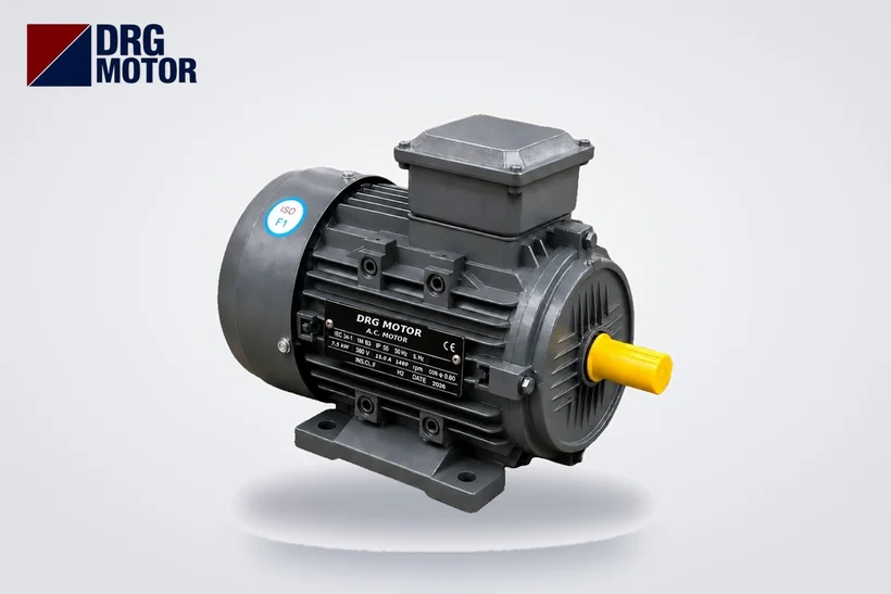
| DRG-132M-4 | 7.5 kW / 1460 rpm | 15.0 A | 14.3 A | 49.1 Nm | Delta |
| DRG-160M-6 | 7.5 kW / 970 rpm | 16.2 A | 15.4 A | 73.8 Nm | Delta |
| DRG-100L2-4 | 3 kW / 1450 rpm | 6.34 A | 6.02 A | 19.8 Nm | Star |
The drive's output voltage determines the terminal connection. Motors with a 400/690 V nameplate (4 kW and above in this range) are connected in delta to a 380–400 V three-phase drive. Motors with a 230/400 V nameplate (3 kW and below) are connected in star to a drive with 400 V output, and in delta to a small single-phase-input drive with 3 × 230 V output. Where a workshop has only a single-phase supply, this last option is a practical solution for small ratings.
Three more points to watch when selecting:
- Cooling at low speed: The fan of a standard motor is mounted on the shaft; as speed drops, cooling air decreases. With fans and pumps, torque also falls with speed so there is little problem; but if the motor will run for long periods near rated torque at low speed on a constant-torque load such as a conveyor, a separately powered external fan or one power size up is considered.
- Insulation and voltage pulses: PWM output applies steep-fronted pulses to the winding; on long cables these pulses can grow by reflection. Details in Why Inverter-Fed Motors Need a Reinforced Insulation System.
- Starting current: Because the drive ramps the motor up from low frequency, the mains does not see the Is/In multiple of a direct start. A 7.5 kW, 4-pole motor draws about 15.0 × 7.5 ≈ 112.5 A on a direct start, whereas with a drive the current stays within the drive's current limit.
Cable and shielding between drive and motor
Most problems with frequency converters come not from the device but from the wiring. Because the drive output contains high-frequency voltage pulses, the cable both radiates electromagnetic noise like an antenna and carries capacitive leakage current.
- Use shielded motor cable between drive and motor; bond the shield to the housing with 360° cable glands at the drive and in the motor terminal box. Twisting the shield into a wire and connecting it at one end ("pigtail") largely destroys its effectiveness at high frequency.
- Connect the motor housing to the drive's earth terminal with a PE conductor; the shield does not replace the PE.
- Route the motor cable in a separate tray from control, analogue signal and communication cables; cross them at right angles.
- For long cable runs, check the length permitted by the drive manufacturer; if exceeded, an output choke or dv/dt filter is used.
- If you put a contactor between drive and motor, control it so that it only switches while the motor is stopped.
- Size the cable by motor current; on long runs also account for voltage drop (motor cable size calculator).
Frequency converter, soft starter or star-delta?
If speed adjustment is not needed, a frequency converter is often a more complex solution than necessary. If the only concern is starting current and mechanical shock, a soft starter is enough; a drive is needed to change speed during operation, to control a process (pressure, flow, tension) or for precise ramps and braking.
| Requirement | Star-delta | Soft starter | Frequency converter |
|---|---|---|---|
| Reduce starting current | Yes (stepped) | Yes (adjustable ramp) | Yes (with current limit) |
| Speed adjustment while running | No | No | Yes |
| High torque at low speed | No | No, starting torque drops | Yes (vector control) |
| Soft stop (water hammer) | No | Yes | Yes |
| Motor connection | 6 leads, motor suitable for 380 V in delta | 3 leads | 3 leads |
| Harmonic effect on the mains | None | Only during start | Yes; choke/filter |
| Typical application | Light-start pump, fan | Fixed-speed pump, fan, compressor | Variable-flow pump, conveyor, mixer |
To compare starting methods by current use the motor starting methods tool, and to select protective devices the overload, fuse and contactor selection tool. To see the effect of a drive on energy use in variable-flow pumps and fans, the energy consumption calculator is a useful guide.
Commissioning checklist for a drive system
- Drive output current ≥ motor nameplate current; one size higher for heavy loads.
- Motor terminal connection suits the drive output voltage (400 V output: 400/690 V motor in delta, 230/400 V motor in star).
- Nameplate values entered into the drive, motor identification performed.
- Minimum and maximum frequency and ramp times set according to the load.
- Cooling at low speed assessed for constant-torque loads.
- Shielded cable, 360° shield bonding and separate PE conductor installed.
- Power and signal cables in separate trays.
- Ventilation in the drive panel and manufacturer clearances around the device.
Motors suitable for drive operation
Models mentioned in the tables of this article:
- DRG-100L2-4 – 3 kW – 1500 rpm – cast iron frame
- DRG-132S2-2 – 7.5 kW – 3000 rpm – cast iron frame
- DRG-132M-4 – 7.5 kW – 1500 rpm – aluminium frame
- DRG-160M-6 – 7.5 kW – 1000 rpm – cast iron frame
- DRG-160M-4 – 11 kW – 1500 rpm – cast iron frame
Click to see current prices and order these motors nowSEE PRICES →
Frequently Asked Questions
Are an inverter and a frequency converter the same thing?
For motor control, yes: in the field they are the same device. Technically, the inverter is the stage that turns DC into variable-frequency AC; the frequency converter is the whole device made up of rectifier, DC bus and inverter.
Does every three-phase motor work with a frequency converter?
The vast majority of standard three-phase induction motors work with a drive. You need to connect the terminals according to the drive output voltage, select the drive by motor current, and take into account cooling during long constant-torque operation at low speed and voltage pulses on long cables.
Can a motor run above 50 Hz with a frequency converter?
Yes, but above 50 Hz the drive cannot increase the voltage, so torque falls: a 4-pole 7.5 kW motor has about 40.9 Nm left at 60 Hz. You must also confirm that the shaft, bearings and driven machine are suitable for the higher speed.
Should I choose a soft starter or a frequency converter for a pump?
If the pump runs at fixed speed and you only need to reduce starting current and water hammer, a soft starter is enough. If flow or pressure varies with demand, a frequency converter that can adjust speed is the better choice.
To determine the power, speed and connection of a motor for drive operation, send us the load type and drive details. Phone: +90 (542) 666 11 11 · E-mail: [email protected] · Contact page. All power and speed options are among the 120 models in our online store.