 English
 Le français
 Türkçe





An electrode-type liquid level relay controls the pump contactor by checking conductivity between three electrodes hanging in the tank. The relay is supplied on A1-A2 and switches its output contact according to whether the Emax (upper), Emin (lower) and common electrodes are wet or dry. That output contact is wired in series with the overload contact in the rung of the K1 contactor coil; the pump motor is switched by K1, not by the relay.
Safety notice: This content is for technical information only. Wiring, measurement and commissioning must be carried out by qualified electrical personnel, following lock-out and verification of de-energised state, and in line with the motor and device manufacturer's documentation.
This article covers electrode layout, the power and control circuits, filling and emptying modes, the state table and the wiring mistakes seen most often on site, each with a diagram. Float-switch control and dry-running protection of the pump are separate topics; only the electrode relay is covered here. Terminal names are generic and vary by device; the device's own wiring diagram always prevails.
How does an electrode level relay sense the liquid?
A conductive liquid such as water lets a small current flow between two electrodes. The relay applies a low voltage from its internal circuit and checks whether that current flows. If an electrode tip touches the liquid it is "wet"; otherwise it is "dry". Many devices use an alternating voltage on the electrodes, which reduces deposits and wear on the electrode surface. This sensing circuit is isolated from the mains, but that should be confirmed for each device.
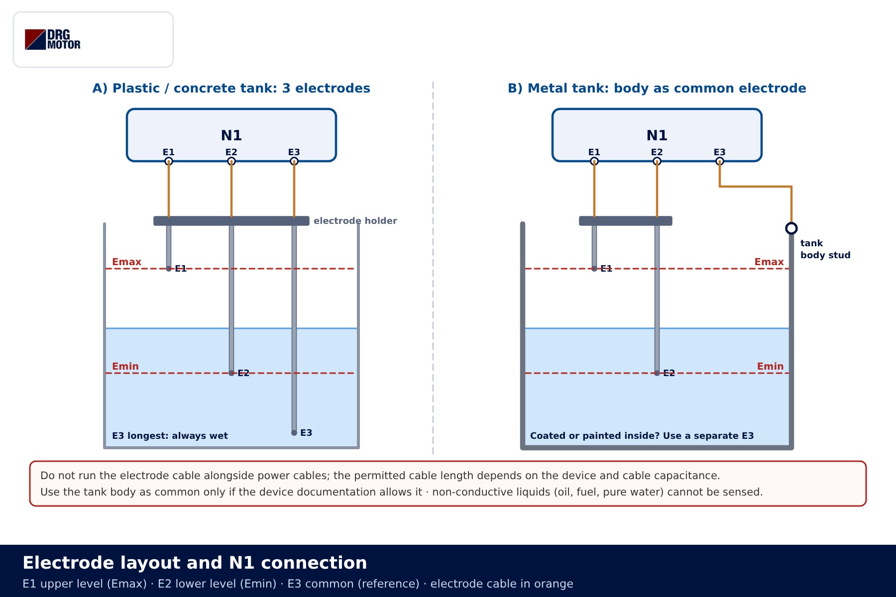
Each of the three electrodes has its own job:
- Emax (E1, upper electrode): the shortest one; its tip sits at the upper level where the pump should stop (filling) or start (emptying).
- Emin (E2, lower electrode): its tip marks the lower level. When the liquid drops below it, the relay changes over.
- Common electrode (E3, reference): the longest one, close to the bottom and always submerged. The other two are measured against it.
In a metal tank with a bare inner surface, the tank body can serve as the common electrode if the device documentation allows it; the E3 terminal is then wired to a stud on the tank wall. If the inside is painted or coated, or the tank is plastic or concrete, a separate E3 electrode is required.
The method only works with conductive liquids. Oil, fuel, solvents and pure (deionised) water conduct too little for the electrodes to detect them; a float, capacitive or other sensing principle is needed there. Areas with flammable liquids also need a separate assessment for explosion protection.
Components and power circuit
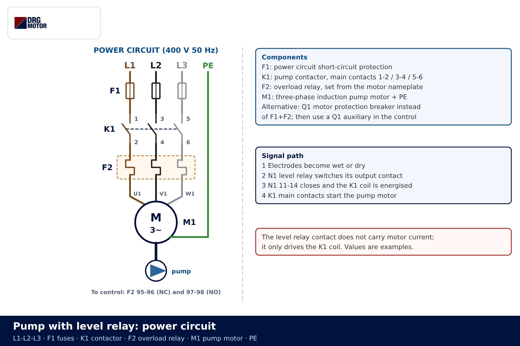
The power circuit is a plain direct-on-line starter: L1-L2-L3 pass through the F1 fuses, the main contacts of contactor K1 and the F2 overload relay to the pump motor. The level relay contact never carries motor current; it only switches the small control current of the K1 coil. A Q1 motor protection breaker can replace F1 and F2 in a single device; the difference is explained in thermal relay vs motor protection breaker.
| Component | Terminals (generic) | Role in the circuit |
|---|---|---|
| N1 level relay | A1-A2 supply · E1 E2 E3 electrodes · 11-12-14 output | Monitors the electrodes and drives the K1 coil through its output contact |
| E1 / E2 / E3 electrodes | Emax / Emin / common | Upper level, lower level and reference |
| F1 fuses | one per phase | Short-circuit protection of the power circuit |
| K1 contactor | A1-A2 coil · 1…6 main · 13-14 auxiliary | Connects the pump motor to the supply |
| F2 overload relay | 95-96 NC · 97-98 NO | Opens the K1 rung on overload and lights the fault lamp |
| F3 control fuse | single pole | Protects the control circuit and the relay supply |
| M1 pump motor | U1 V1 W1 + PE | Three-phase induction motor; terminal link per nameplate |
Click to see current electric motor prices and order nowSEE PRICES →
Control circuit: wiring the relay output into the K1 rung
The control circuit has L on the top rail (230 V AC in the example) and N on the bottom rail. The first rung supplies the relay itself: after the F3 fuse, L goes to N1 terminal A1 and A2 returns to N. The supply voltage depends on the device (it may be AC or DC); stay within the rating on its label.
The second rung is the pump rung. L passes through F2 contact 95-96, then through terminals 11 (common) and 14 (normally open) of the N1 changeover output, and reaches A1 of the K1 coil. When the relay decides the pump must run, 11-14 closes and K1 picks up. Terminal 12 stays free in this example; some devices ask for 11-12 to be used in the pump rung instead. Which terminal to use depends on the selected mode and on the device wiring diagram.
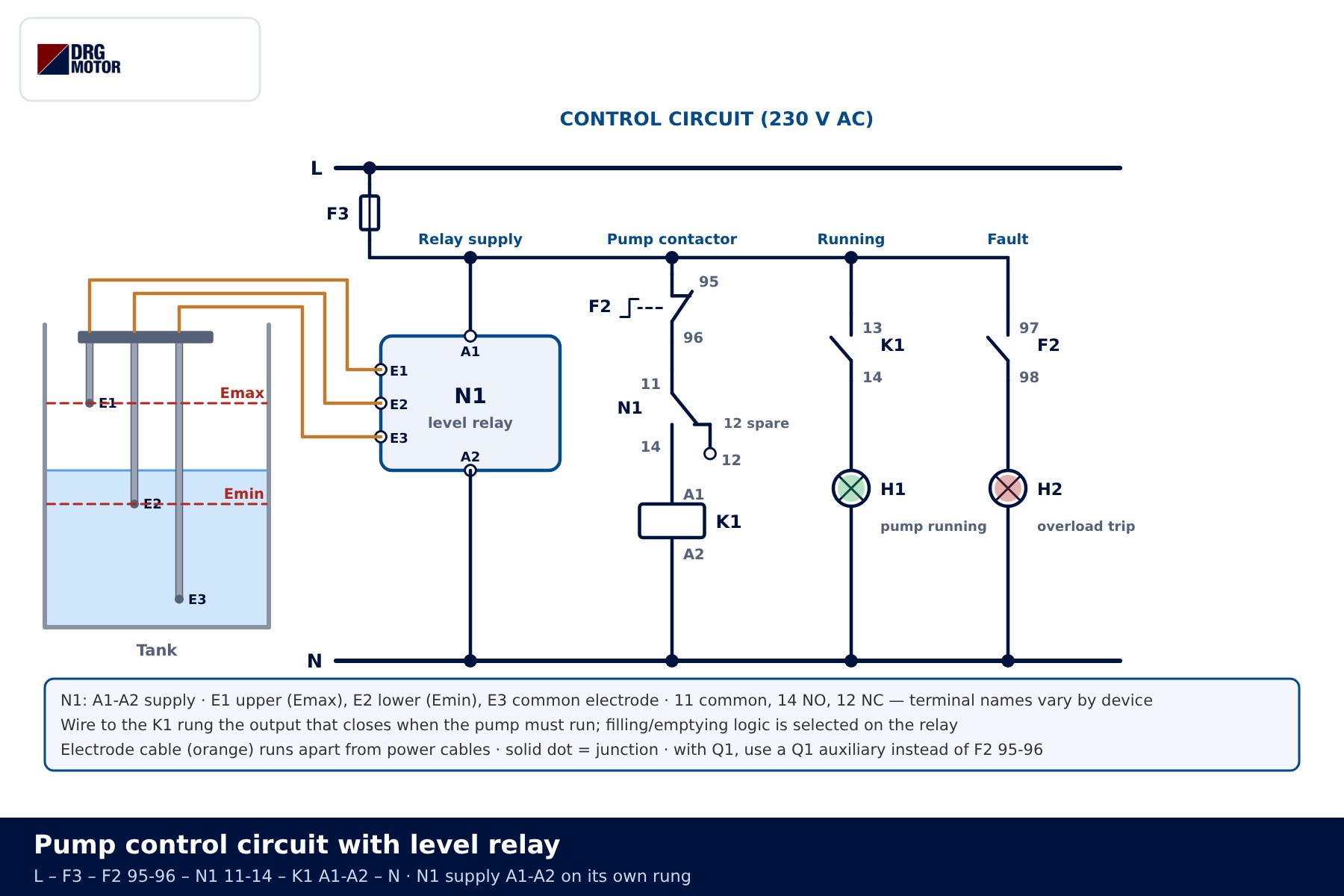
There is no self-holding contact here as in a start-stop circuit. The relay does the holding itself: between Emin and Emax it keeps its output in the previous state. Adding an extra holding contact can stop the pump from switching off at the upper level. If a Q1 motor protection breaker is used, its auxiliary contact takes the place of F2 95-96 in this rung.
Two optional lamps are shown: H1 "pump running" lights via K1 13-14 and H2 "overload trip" via F2 97-98. They are not needed for the circuit to work, but they save a lot of time when tracing a fault.
📄 Download Wiring Diagram PDF A4 printable PDF of the diagrams and tables (no sign-up)
Filling mode and emptying mode
The same relay and electrode layout can do two opposite jobs. The difference is the mode selector on the relay (a switch, rotary selector or jumper; the name varies by device).
- Filling mode: a header tank, cistern or storage tank is kept full. The pump starts when the level falls below Emin and stops when it reaches Emax.
- Emptying mode: a drainage pit or waste-water sump is kept empty. The pump starts when the level reaches Emax and stops when it falls below Emin.
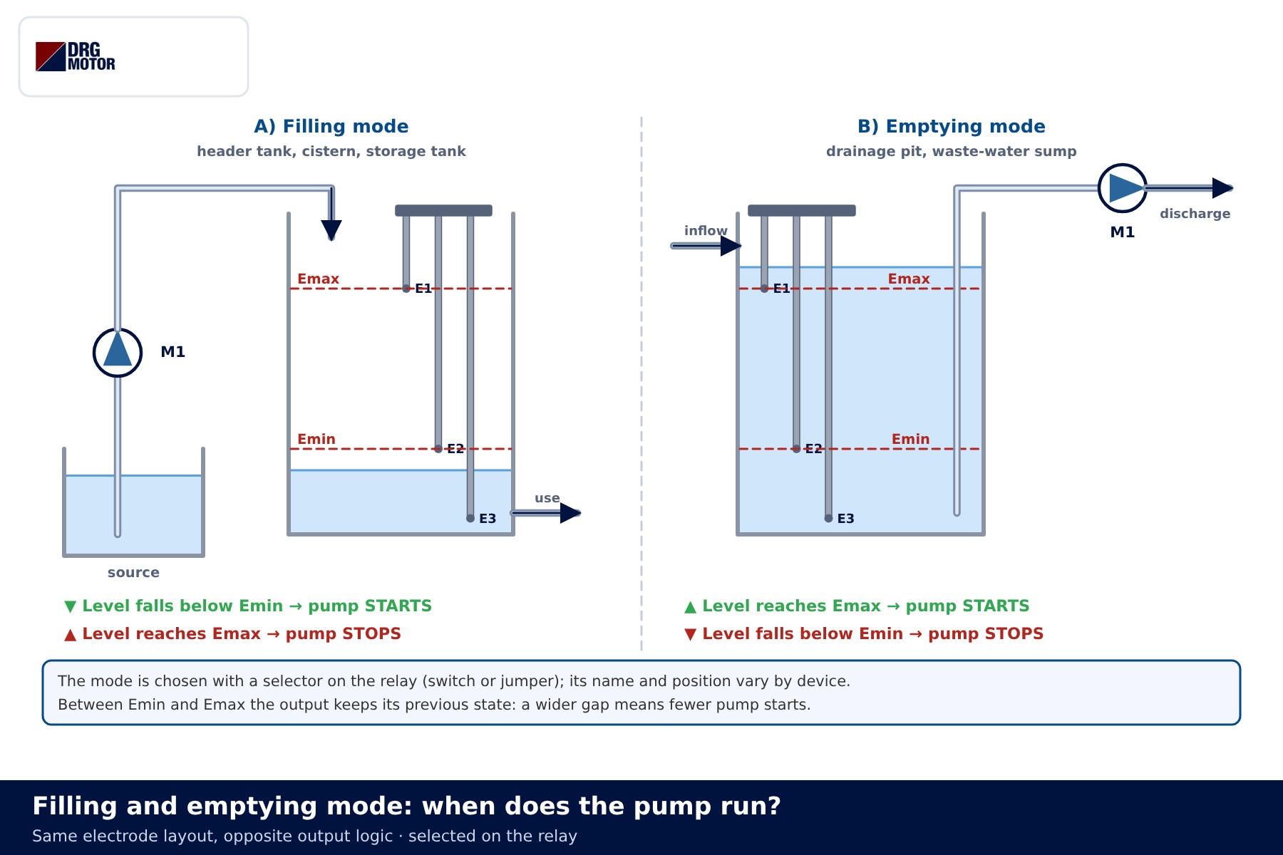
With the wrong mode the pump does exactly the opposite: it stays off while the tank to be filled is empty, or waits while the sump overflows. The first commissioning step is to wet and dry the electrodes by hand and confirm that the output changes in the right direction.
Step-by-step operation and state table
In filling mode one cycle runs as follows:
- Level below Emin: E1 and E2 are dry. The relay closes 11-14, K1 picks up, the pump runs.
- Level rising between Emin and Emax: E2 is wet, E1 still dry. The relay keeps its previous decision, so the pump keeps running.
- Level reaches Emax: E1 becomes wet too. The relay opens 11-14, K1 drops out, the pump stops.
- Consumption lowers the level: E1 is dry again, E2 still wet. The relay holds its last decision; the pump stays off.
- Level below Emin again: E2 dries and the cycle restarts.
Steps 2 and 4 have the same electrode state; the output depends on the direction the level came from. This is hysteresis, and it is what prevents the pump from cycling too often. The larger the distance between Emin and Emax, the fewer the pump starts.
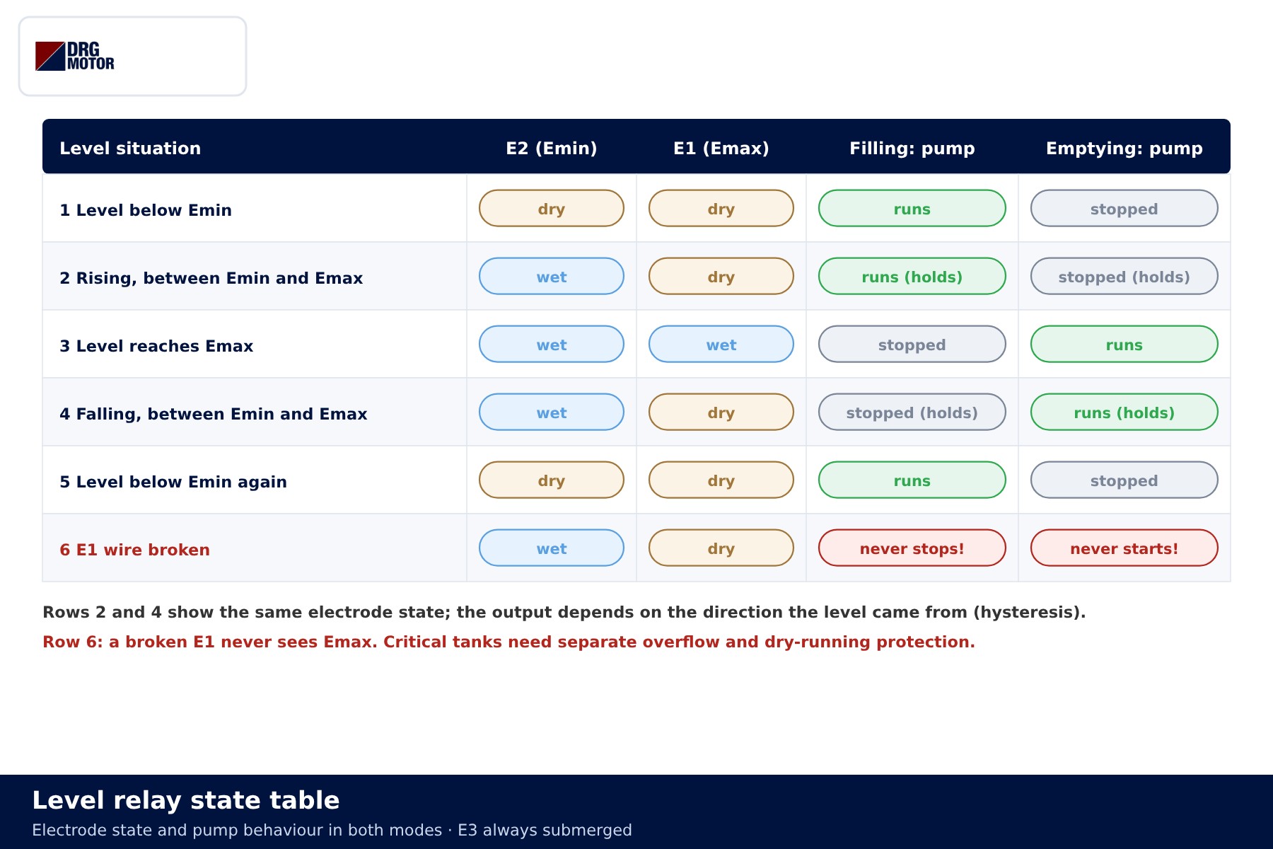
| Situation | Electrodes | Filling: pump | Emptying: pump |
|---|---|---|---|
| Level below Emin | E1 dry, E2 dry | runs | stopped |
| Between Emin and Emax, rising | E1 dry, E2 wet | keeps running | stays stopped |
| Level at Emax | E1 wet, E2 wet | stopped | runs |
| Between Emin and Emax, falling | E1 dry, E2 wet | stays stopped | keeps running |
| Relay supply lost | — | stopped | stopped |
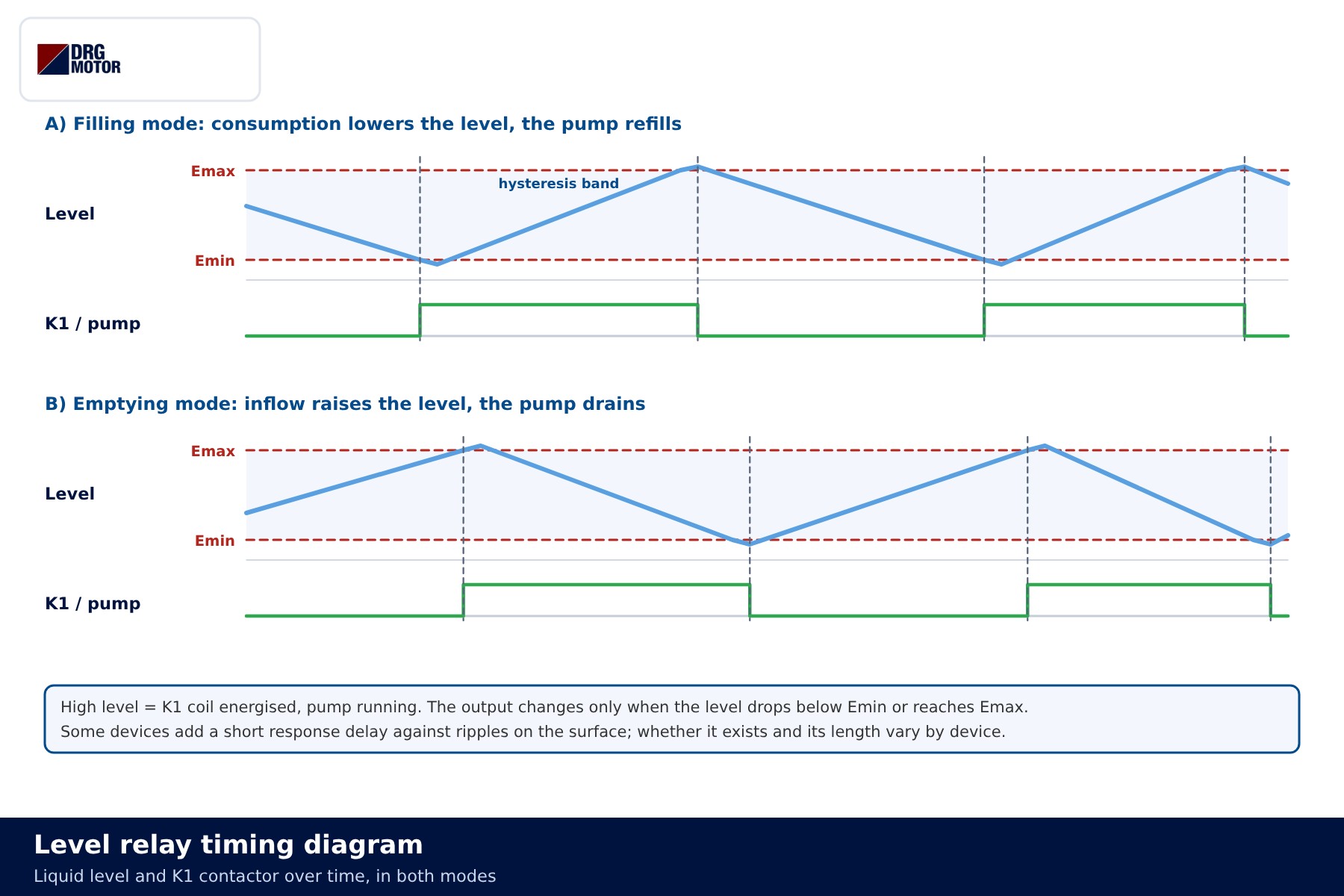
The timing diagram shows the same cycle over time. While the level curve moves between the Emin and Emax lines, the K1 signal changes only at the moments the curve touches one of those lines. Some devices add a short response delay to avoid needless switching on a rippling surface; whether it exists and how long it is depends on the device.
Sensitivity adjustment and electrode cable
Liquids differ widely in conductivity: mains water, well water, rainwater and waste water pass different currents through the same electrodes. That is why most relays have a sensitivity (conductivity) adjustment. Set too low, the relay reads a wet electrode as dry; set too high, moisture, foam or dirt on the electrode holder can make a dry electrode look wet. Follow the method in the device documentation, typically finding the point where the output switches reliably with the electrodes in and out of the liquid. No single setting suits every liquid.
The electrode cable is part of the measurement. On a long cable the capacitance between cores can make even a dry electrode look wet, so the permitted length depends on the device and the cable used; on long runs use the cable type recommended by the device maker. Never lay the electrode cable alongside motor power cables in the same duct: voltage induced from the power cable causes false readings. Mount the electrode holder in a calm spot, away from surface waves and water falling from the inlet pipe.
Common wiring mistakes
| Symptom | Likely cause |
|---|---|
| Pump does not stop at Emax, tank overflows | Wrong mode selected, E1 wire broken, or E1 and E2 swapped |
| Pump never starts | No supply on A1-A2, 11-12 wired instead of 11-14, or F2 95-96 open |
| Pump cycles very often | E1 and E2 tips too close, electrodes in a turbulent zone, or common electrode coming out of the liquid |
| Relay reads "full" with an empty tank | Sensitivity too high, dirt or moisture bridge on the holder, or cable too long |
| Relay reads "empty" with a full tank | Liquid conductivity too low, sensitivity too low, or painted metal tank used as common |
| Relay changes over by itself now and then | Electrode cable in the same duct as power cables, or loose electrode terminal |
If the overload relay trips repeatedly, the cause is usually the pump or the motor rather than the control circuit; see why an electric motor trips the overload relay. The level relay only watches the tank level; protecting the pump against running dry on the suction side needs a separate device and is covered in its own article.
Choosing the pump motor
Pumps controlled by a level relay are mostly driven by 3000 rpm class three-phase motors started direct on line. Motor power follows from the pump's flow and head; the contactor and overload relay are then selected from the rated current on the motor nameplate. For starting values use the overload, fuse and contactor selection tool and the motor current chart, and for the cable the motor cable size calculator; no single cross-section fits every installation.
What to check when replacing a burnt pump motor is explained in why a booster pump motor burns out. Larger pumps may need a different starting method; the level relay output then takes the place of the start button, for example in a star-delta control circuit.
📄 Download Wiring Diagram PDF A4 printable PDF of the diagrams and tables (no sign-up)
Send a photo of your current motor nameplate and we will find the suitable DRG model together.Send on WhatsApp
DRG motors for level-controlled pumps
DRG Motor is an electric motor manufacturer, supplier and seller. The 3000 rpm class three-phase IEC motors below are in the power range commonly found on pumps controlled by a level relay. Level relays, electrodes, contactors and overload relays are not sold by DRG; please contact your panel component supplier for those. Other powers and speeds are listed on the three-phase asynchronous electric motors page and in the online store.
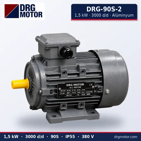
1.5 kW Three-Phase Motor 3000 rpm – DRG-90S-2 Aluminium
- 1.5 kW · 3000 rpm (2 poles)
- Aluminium frame · IEC 90S
- Mounting: B3 · B5 · B14 · B35
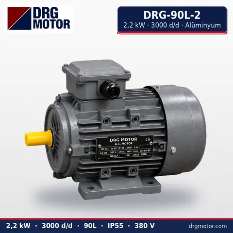
2.2 kW Three-Phase Motor 3000 rpm – DRG-90L-2 Aluminium
- 2.2 kW · 3000 rpm (2 poles)
- Aluminium frame · IEC 90L
- Mounting: B3 · B5 · B14 · B35
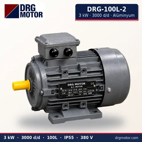
3 kW Three-Phase Motor 3000 rpm – DRG-100L-2 Aluminium
- 3 kW · 3000 rpm (2 poles)
- Aluminium frame · IEC 100L
- Mounting: B3 · B5 · B14 · B35
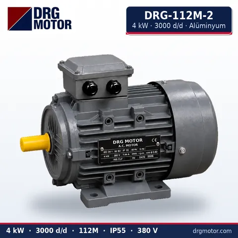
4 kW Three-Phase Motor 3000 rpm – DRG-112M-2 Aluminium
- 4 kW · 3000 rpm (2 poles)
- Aluminium frame · IEC 112M
- Mounting: B3 · B5 · B14 · B35
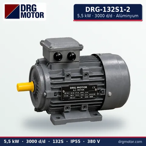
5.5 kW Three-Phase Motor 3000 rpm – DRG-132S1-2 Aluminium
- 5.5 kW · 3000 rpm (2 poles)
- Aluminium frame · IEC 132S
- Mounting: B3 · B5 · B14 · B35
Click to see current prices for these motors and order nowSEE PRICES →
Frequently asked questions
Can the level relay contact switch the pump motor directly?
Not for a three-phase pump motor. The relay output is rated for a small control current; K1 switches the motor and the relay only drives the K1 coil.
Why must the common electrode be the longest?
The measurement is made against the common electrode. If it leaves the liquid, the relay sees E1 and E2 as dry, and in filling mode the pump may never stop. Its tip is therefore placed near the bottom so it is always submerged.
Does a metal tank need a separate common electrode?
Where the inner surface is bare metal and the device documentation allows it, the tank body can be the common electrode. Painted, coated, plastic or concrete tanks need a separate common electrode.
Can an electrode relay be used for oil or pure water?
No. Oil, fuel and pure water are not conductive enough for the electrodes to detect them. Use a float switch or a sensor based on another principle for such liquids.
What if the pump starts too often?
First check the distance between the E1 and E2 tips: the larger it is, the less often the pump starts. Also make sure the electrodes are not in a turbulent zone and the common electrode stays submerged at all times.





