 English
 Le français
 Türkçe





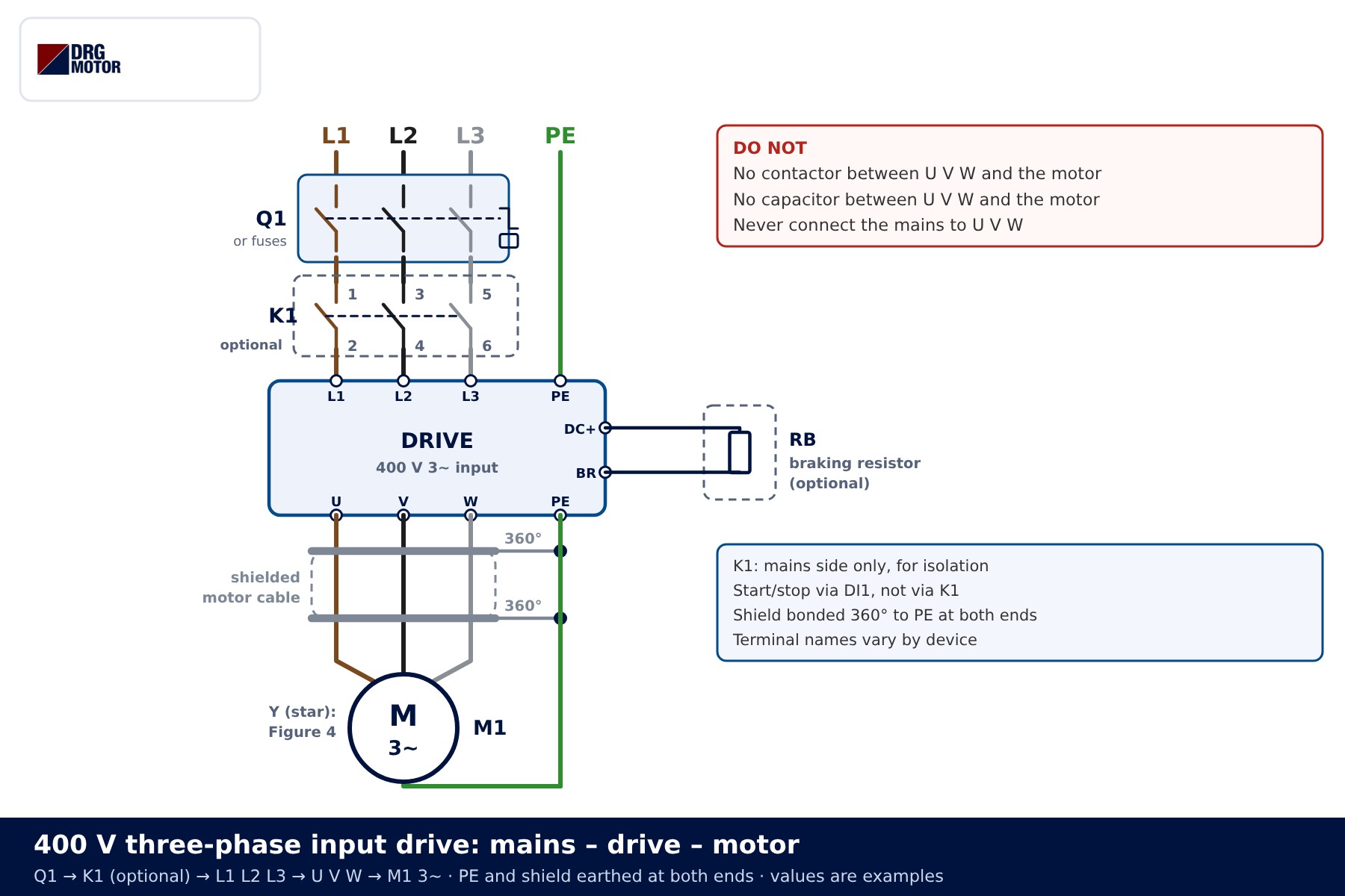
To wire a frequency inverter (drive), the supply runs through a protective device Q1 and an optional line contactor to the drive’s L1 L2 L3 input terminals (L N on single-phase models), and the motor is connected to the U V W output terminals with a shielded cable; the PE conductor and the cable shield are earthed at both the drive and the motor. No contactor or capacitor goes between the drive output and the motor. Whether the motor is connected in star or delta depends on the drive’s output voltage.
Safety notice: This content is for technical information only. Wiring, measurement and commissioning must be carried out by qualified electrical personnel, following lock-out and verification of de-energised state, and in line with the motor and device manufacturer's documentation.
This article shows the power wiring, control terminals, motor terminal box and cable routing in separate diagrams. Terminal names are generic; terminal names vary by device and the device’s own wiring diagram prevails. If the words “inverter”, “frequency converter” and “drive” confuse you, see frequency converter vs inverter.
What does a drive installation consist of?
A drive panel contains three separate circuits: the supply from the mains to the drive, the output from the drive to the motor, and the control wiring that carries start, direction and speed commands. Each has its own cable, protection and earthing.
| Component | Terminals | Role |
|---|---|---|
| Q1 motor protection breaker or fuses | supply side | Protects the drive supply against short circuit; type and rating follow the device documentation |
| K1 line contactor (optional) | 1-2 / 3-4 / 5-6 | Isolates the drive on the mains side only; not used to stop the motor |
| Drive power input | L1 L2 L3 or L N, PE | Takes the mains, rectifies it and converts it to a variable-frequency output |
| Drive power output | U V W, PE | Feeds the motor; the mains is never connected here |
| Shielded motor cable | U V W + PE + shield | Shield bonded 360° at both ends to limit interference |
| Braking resistor RB (optional) | DC+ / BR (device-dependent) | Turns energy fed back by the motor during fast stops into heat |
| M1 three-phase motor | U1 V1 W1, PE | Terminal links set to star or delta to suit the drive output voltage |
How is a 400 V three-phase input drive wired?
The sequence for a three-phase input drive is shown in Figure 1. In practice:
- Isolate the supply, lock Q1 in the open position and verify absence of voltage.
- Connect the mains phases through Q1 (and K1 if fitted) to L1 L2 L3, and the protective conductor to PE.
- Connect the three motor cores to U V W and the green-yellow core to the PE terminal on the output side. Swapping U and V only reverses rotation; direction can also be changed by parameter.
- Bond the shield 360° to the mounting plate with a clamp at the drive, and to the motor frame with an EMC gland at the motor.
- Set the links in the motor terminal box to match the drive output voltage (see the star/delta section below).
- If a braking resistor is used, connect it to the relevant drive terminals; its value and power rating come from the device documentation — no settings are given here.
The K1 line contactor is not mandatory. It is used where emergency stopping or remote isolation is required, but it is not cycled to start and stop the motor; start and stop come from the control terminals. The drive’s internal capacitors stay charged for some time after isolation, so wait for the time marked on the device before touching the terminals.
Why no contactor or capacitor between the drive output and the motor?
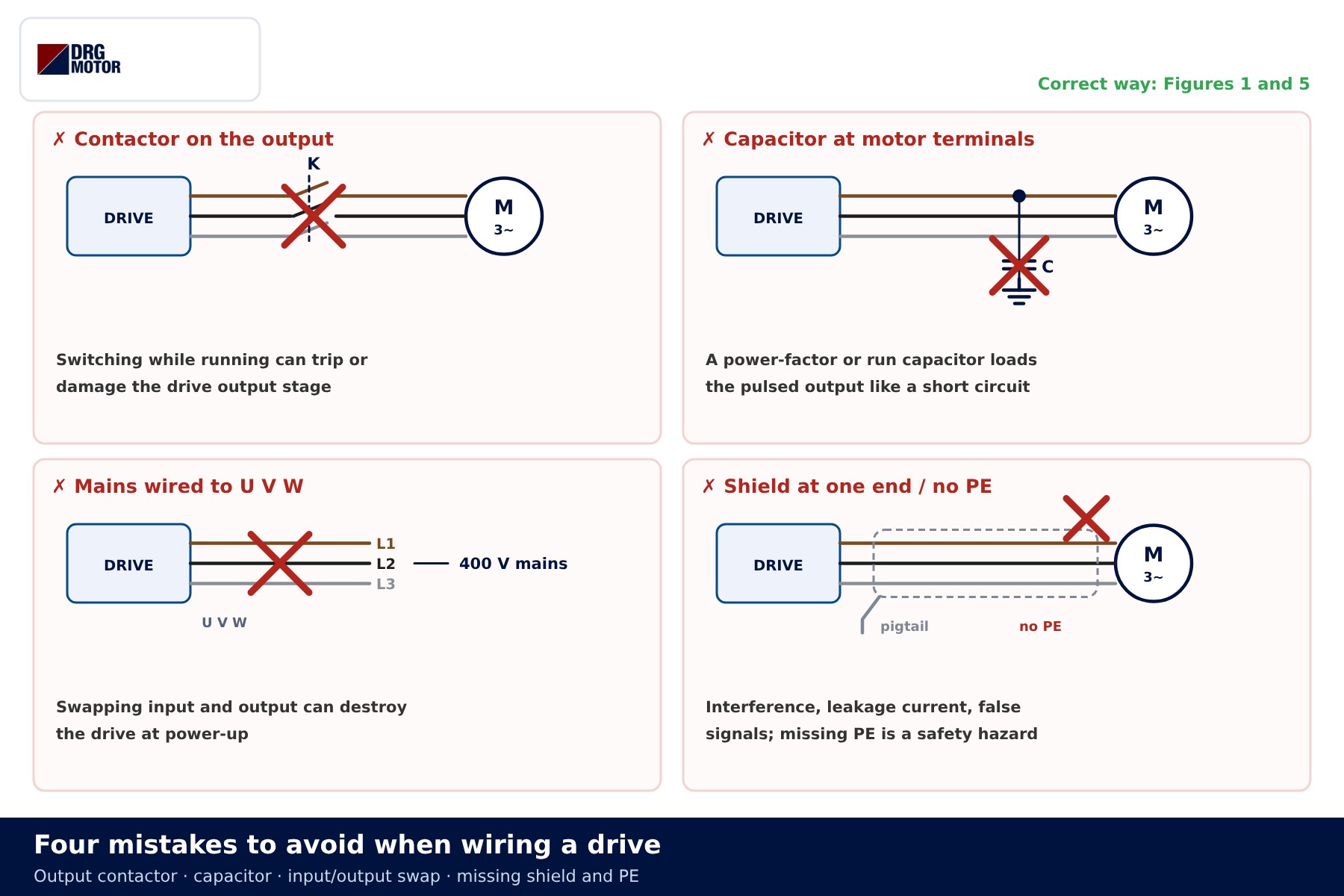
The drive output is not a sine wave but a train of high-frequency voltage pulses. A capacitor on the output — power-factor correction or a single-phase run capacitor — draws a charging current spike on every pulse; the drive sees this as a short circuit, trips or may damage its output stage. A contactor that opens or closes on the output while the motor is running causes arcing and a current surge, and the drive trips on overcurrent. If the site requires isolation on the motor side for maintenance, use an arrangement that only opens with the drive stopped and signals “stop” to the drive, as recommended by the device manufacturer.
📄 Download Wiring Diagram PDF A4 printable PDF of the diagrams and tables (no sign-up)
Wiring a 220 V single-phase input drive
Some small drives are supplied from a 230 V single-phase network and produce a 3×230 V three-phase output. On the input, a two-pole Q1 feeds the phase to L, neutral to N and the protective conductor to PE; the output side is the same as on a three-phase drive. The difference is on the motor: for a 3×230 V output, choose a three-phase motor with 230/400 V on the nameplate and connect it in delta.
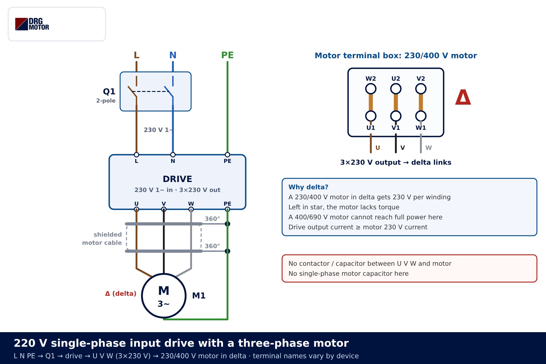
No single-phase motor capacitor is used here: the motor is three-phase and the drive generates the three phases itself. The drive output current must not be lower than the motor’s 230 V delta current. We worked through the power limit with examples in motor selection for a 220 V inverter.
Click to see current electric motor prices and order nowSEE PRICES →
Should the motor be connected in star or delta?
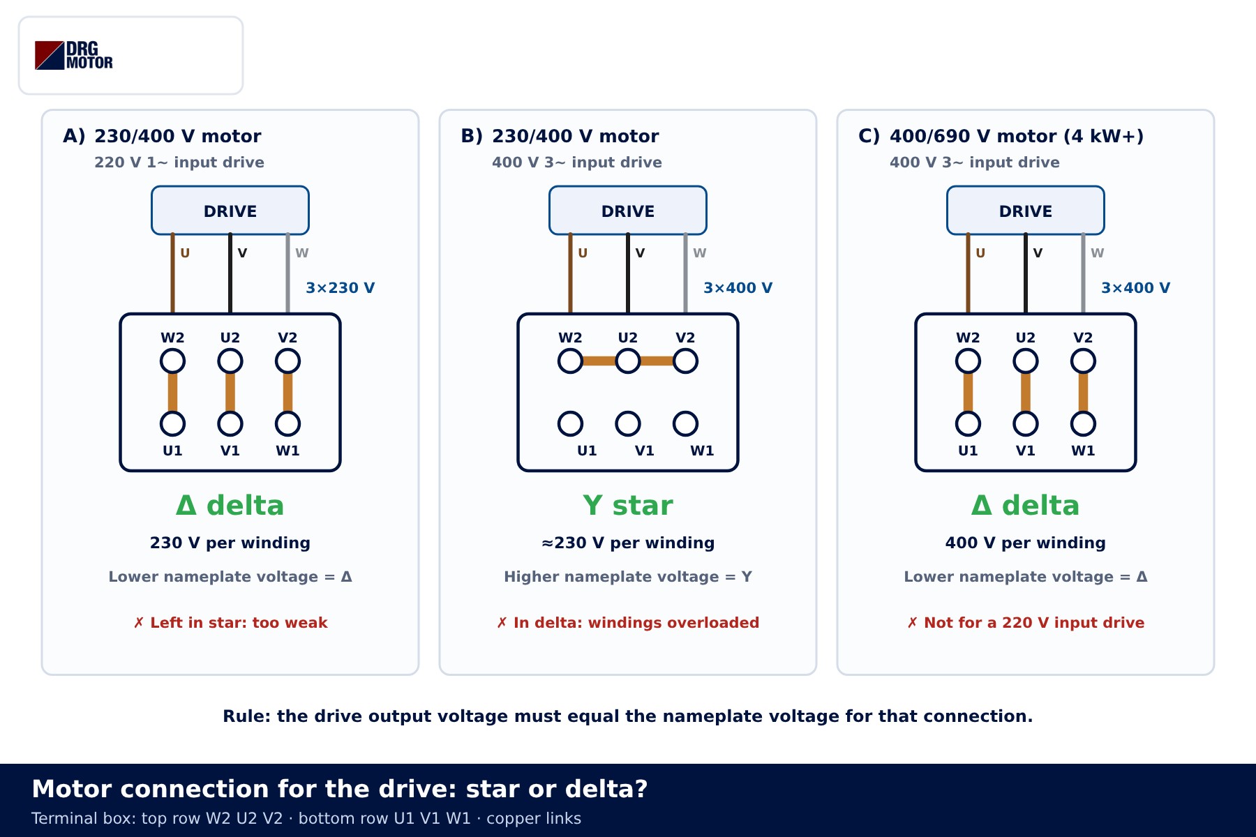
The rule is simple: the drive output voltage must equal the nameplate voltage for the chosen connection. The lower nameplate voltage corresponds to delta, the higher one to star. Because the drive already starts the motor smoothly, no star-delta starter is needed.
| Drive input / output | Motor nameplate | Terminal connection |
|---|---|---|
| 230 V 1~ / 3×230 V | 230/400 V | Delta (Δ) |
| 400 V 3~ / 3×400 V | 230/400 V | Star (Y) |
| 400 V 3~ / 3×400 V | 400/690 V | Delta (Δ) |
| 230 V 1~ / 3×230 V | 400/690 V | Not suitable; full power not reached |
DRG motors up to 3 kW are rated 230/400 V; from 4 kW they are 400/690 V. How to fit the links in the terminal box is shown step by step in the star-delta connection diagram article.
Control terminals: start, direction, speed and fault
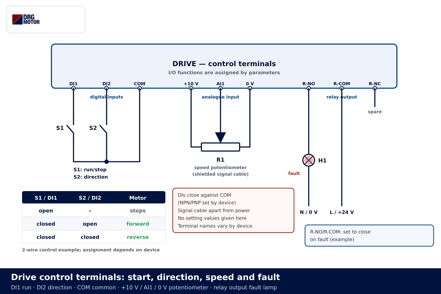
Using generic names, the control terminals include digital inputs DI1 and DI2 with their common COM, +10 V, AI1 and 0 V for the speed reference, and a relay output for fault indication. Which input does what is assigned by drive parameters; the figure shows a typical two-wire example.
Sequence of operation:
- When the run switch closes, DI1 is connected to COM; the drive ramps up to the speed set by the potentiometer.
- When the direction switch closes, DI2 becomes active; the drive decelerates, stops and accelerates in the opposite direction. No separate interlock is needed as in a contactor reversing circuit — the drive handles the reversal.
- The potentiometer sits between +10 V and 0 V, with its wiper on AI1; turning it changes the speed reference.
- When the run switch opens, the drive stops the motor on its ramp or by coasting.
- On a fault such as overcurrent, overvoltage or motor overheating, the drive cuts its output and the relay output changes state; the fault lamp lights.
| Run (DI1) | Direction (DI2) | Motor |
|---|---|---|
| open | any | stopped |
| closed | open | runs forward |
| closed | closed | runs in reverse |
NPN/PNP input logic, ramp times and motor nameplate data are set on the device; we give no fixed values — enter them from the motor nameplate and the device documentation. Emergency stopping is not shown here; where needed, the safety function is designed on the basis of a risk assessment.
Cable routing, shielding and earthing
Most problems in drive installations come not from wrong terminals but from cable routing. The layout in Figure 5 follows these rules:
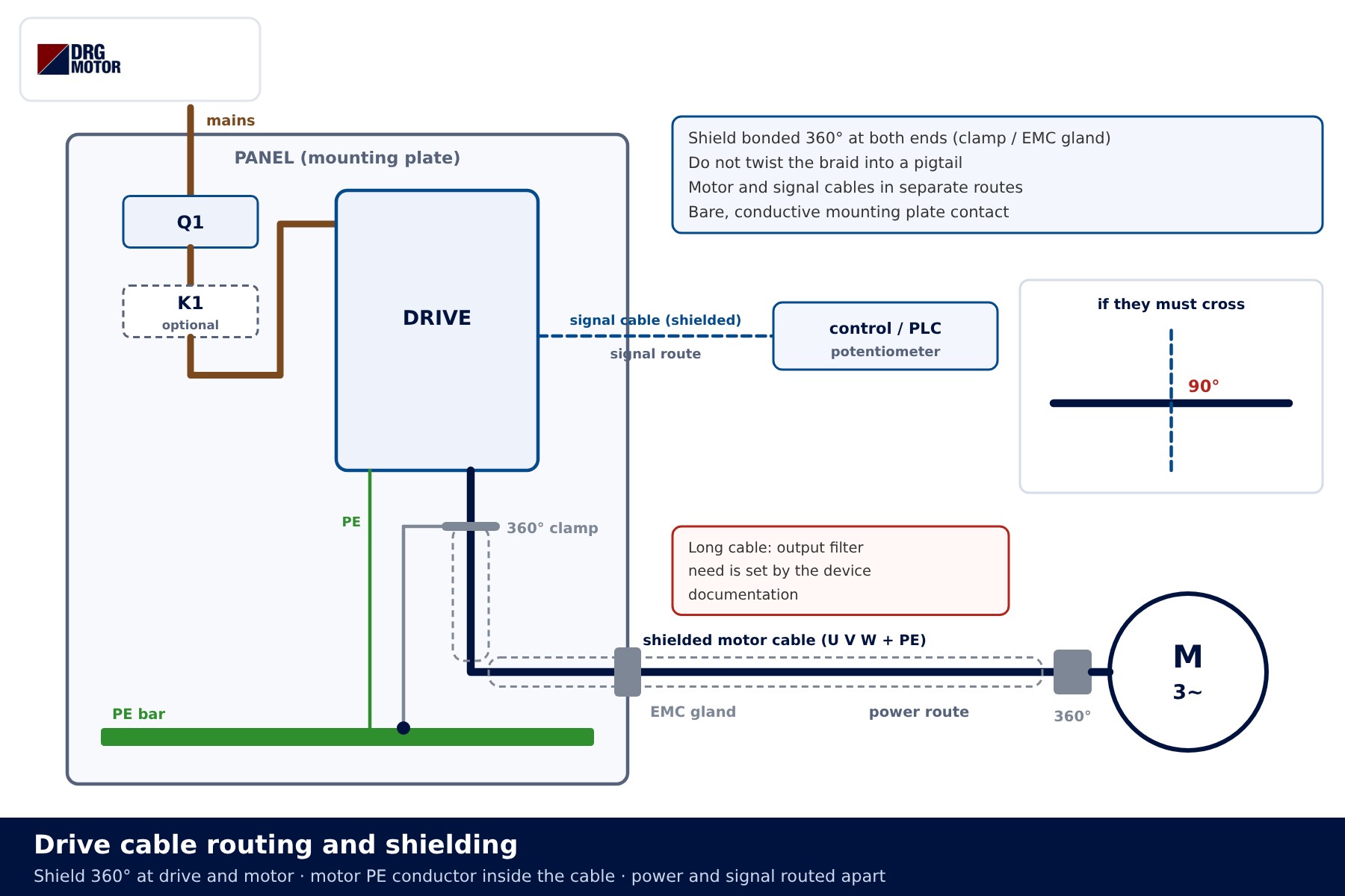
- Use a shielded motor cable; bond the shield all round (360°) to a bare mounting plate with a clamp at the drive and to the frame with an EMC gland at the motor.
- Do not twist the braid into a single pigtail on a terminal; at high frequency it loses most of its effect.
- Run the motor PE conductor inside the motor cable; do not rely on the shield alone.
- Route the motor cable and the potentiometer/PLC signal cable separately; where they must cross, cross at right angles.
- With long motor cables, whether an output filter is needed is decided from the device documentation.
Check the cable size for current, length and installation method with the motor cable size calculator. For winding insulation and cooling on motors that run at low speed on a drive for long periods, see VFD motor insulation and forced cooling.
Common wiring mistakes
| Symptom | Likely cause | Check |
|---|---|---|
| Drive damaged at first power-up | Mains connected to U V W | Input and output terminal markings |
| Overcurrent trip on start | Capacitor at motor terminals or contactor on the output | Every item between U V W and the motor |
| Motor runs unloaded, stalls under load | Motor left in star on a 230 V output | Terminal links and nameplate voltage |
| Sensors and analogue speed unstable | Shield at one end only or signal cable in the power route | Shield clamps, cable routes |
| Residual current device trips | Long shielded cable, unsuitable RCD type | Leakage current advice in the device documentation |
| Motor does not start at all | DI1 or COM not connected, speed reference zero | Input status display, AI1 voltage |
Selection examples
- Workshop with a 230 V single-phase supply, 1.5 kW conveyor: 230 V input drive + DRG-90L-4 (230/400 V), terminals in delta. Pick a drive whose output current exceeds the motor’s 230 V current.
- 400 V three-phase plant, 3 kW fan: 400 V input drive + DRG-100L2-4 (230/400 V), terminals in star.
- 400 V three-phase plant, 4 kW pump: 400 V input drive + DRG-112M-4 (400/690 V), terminals in delta. This motor will not deliver full power on a 230 V output drive.
Compare nameplate currents in the motor current chart and size the drive by output current rather than by kW.
📄 Download Wiring Diagram PDF A4 printable PDF of the diagrams and tables (no sign-up)
Send a photo of your current motor nameplate and we will find the suitable DRG model together.Send on WhatsApp
DRG motors suitable for drive operation
DRG Motor is an electric motor manufacturer, supplier and seller. The three-phase IEC motors below are in the power range often used with drives; the 230/400 V models suit both 220 V and 400 V input drives, the 400/690 V model suits 400 V input drives. Frequency inverters, braking resistors and panel components are not sold by DRG; please contact your panel component supplier or the device manufacturer. Other ratings and speeds are listed on the three-phase asynchronous electric motors page and in the online store.
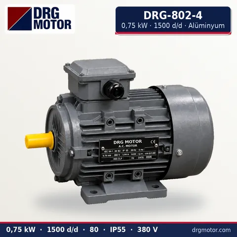
0.75 kW Three-Phase Motor 1500 rpm – DRG-802-4 Aluminium
- 0.75 kW · 1500 rpm (4 poles)
- Aluminium frame · IEC 80
- Mounting: B3 · B5 · B14 · B35
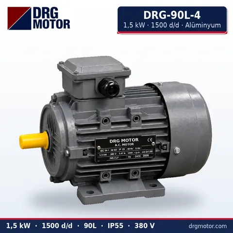
1.5 kW Three-Phase Motor 1500 rpm – DRG-90L-4 Aluminium
- 1.5 kW · 1500 rpm (4 poles)
- Aluminium frame · IEC 90L
- Mounting: B3 · B5 · B14 · B35
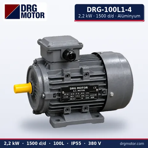
2.2 kW Three-Phase Motor 1500 rpm – DRG-100L1-4 Aluminium
- 2.2 kW · 1500 rpm (4 poles)
- Aluminium frame · IEC 100L
- Mounting: B3 · B5 · B14 · B35
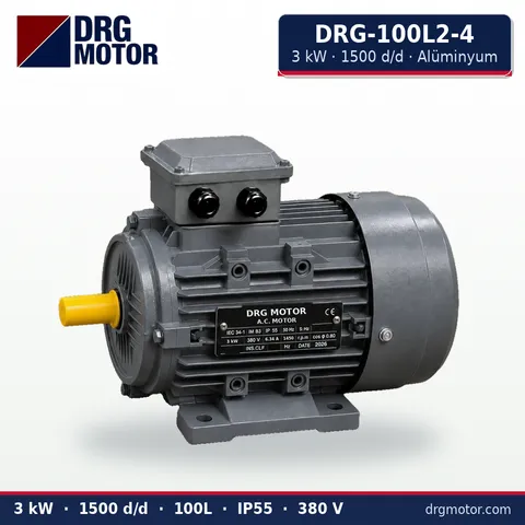
3 kW Three-Phase Motor 1500 rpm – DRG-100L2-4 Aluminium
- 3 kW · 1500 rpm (4 poles)
- Aluminium frame · IEC 100L
- Mounting: B3 · B5 · B14 · B35
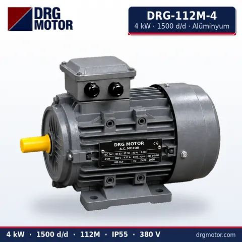
4 kW Three-Phase Motor 1500 rpm – DRG-112M-4 Aluminium
- 4 kW · 1500 rpm (4 poles)
- Aluminium frame · IEC 112M
- Mounting: B3 · B5 · B14 · B35
Click to see current prices for these motors and order nowSEE PRICES →
Frequently asked questions
Is an overload relay needed between the drive and the motor?
With one motor per drive, motor protection is usually provided by the drive’s own electronic overload function, using the nameplate current entered into the device. If one drive feeds several motors, each motor needs its own protection; follow the device documentation in that case.
How is the direction of rotation changed?
With the supply isolated, swap two of the U V W leads, or change direction through an input such as DI2 or by parameter. Changing the L1 L2 L3 order on the mains side does not change motor direction.
Is shielded cable mandatory?
Because the drive output consists of high-frequency pulses, an unshielded cable can disturb nearby signal lines and equipment. EMC requirements and cable length limits are given in the device documentation; shielded motor cable is common practice.
Is a braking resistor always required?
No. Loads that slow down on their own, such as fans and pumps, usually do without one. High-inertia loads stopped on short ramps, or lowering hoists, may need one; selection follows the device documentation.





