 English
 Le français
 Türkçe





On an electrical panel schematic every device appears as a standard IEC 60617-style symbol, with a letter code (Q, K, F, S, H, M, KT) and terminal numbers. An NO (normally open) contact is open while its coil is de-energised and closes when the coil picks up; an NC (normally closed) contact does the opposite. All contacts are drawn de-energised with no button pressed, and that single rule is the key to reading any diagram.
⚠ This content is for technical information only. Wiring, measurement and commissioning must be carried out by qualified electrical personnel, following lock-out and verification of de-energised state, and in line with the motor and device manufacturer's documentation.
This guide shows the symbols you meet most often in motor panels, compares NO and NC contacts in the energised and de-energised states, and explains where numbers such as 13-14, 21-22, 95-96 and A1-A2 come from. At the end we read a small start-stop schematic built from these symbols.
What do the letter codes on a panel diagram mean?
Next to each element you will find a letter and a number: K1, F2, S0 and so on. The letter tells you the device type, the number tells you which device of that type it is. This is how the main contacts of a contactor in the power circuit are matched to its auxiliary contacts in the control circuit, even when they sit on different sheets.
| Code | Device | Example on the drawing |
|---|---|---|
| Q | Switch, motor protection breaker | Q1 – main motor protection |
| K | Contactor, auxiliary relay | K1 – contactor that runs the motor |
| KT | Timer relay | KT1 – star-delta changeover time |
| F | Fuse, overload relay | F1 power fuse, F2 overload, F3 control fuse |
| S | Push-button, selector, limit switch | S0 stop, S2 start, S4 limit |
| H | Indicator lamp, horn | H1 running, H2 fault |
| M | Motor | M1 – three-phase induction motor |
| X | Terminal block | X1:1 – field cable terminal |
These letters reflect common practice. Newer editions of the standard may use two-letter codes, and if a project has its own legend, that legend always applies.
Control and switching symbols
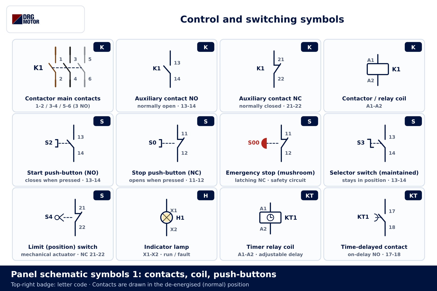
The figure below collects the symbols used most in motor control. Each cell shows the letter code in the top-right corner, with the name and terminal numbers underneath.
| Symbol | What it tells you | Typical terminals |
|---|---|---|
| Contactor main contacts | Three NO contacts carrying motor current; the dashed line shows they move together | 1-2 / 3-4 / 5-6 |
| Auxiliary contact NO | Closes when the coil picks up; used for self-holding and run lamps | 13-14, 43-44 |
| Auxiliary contact NC | Opens when the coil picks up; used for interlocks and "stopped" signals | 21-22, 31-32 |
| Coil | Rectangle that operates the contactor or relay | A1-A2 |
| Start push-button | Spring-return NO; closed only while held | 13-14 |
| Stop push-button | Spring-return NC; opens the circuit when pressed | 11-12 |
| Emergency stop | Mushroom-head NC that latches; released by twisting | 11-12 |
| Selector switch | Stays where you leave it (hand/auto, 0/1) | 13-14 |
| Limit switch | Operated mechanically by a moving part of the machine | 21-22 / 13-14 |
| Timer relay | Coil with a clock mark; contact with a half-circle mark | A1-A2, 15-16-18 |
The difference between a push-button and a selector shows in the actuator: a button has a plain "T" head, a selector has a bent lever and does not spring back. The half-circle on a timer contact means the contact waits for the set time before changing state. You can see these contacts working together in the star-delta control circuit article.
The emergency stop has its own symbol. This latching mushroom button should not be treated as an ordinary stop button; the safety function is designed on the basis of a risk assessment.
📄 Download Wiring Diagram PDF A4 printable PDF of the diagrams and tables (no sign-up)
Click to see current electric motor prices and order nowSEE PRICES →
Protection, power and conductor symbols
In the power circuit motor current flows from top to bottom: L1, L2 and L3 enter at the top and pass through the protection device, the contactor and the overload relay before reaching the motor. Conductor colours are drawn as L1 brown, L2 black, L3 grey and PE green-yellow.
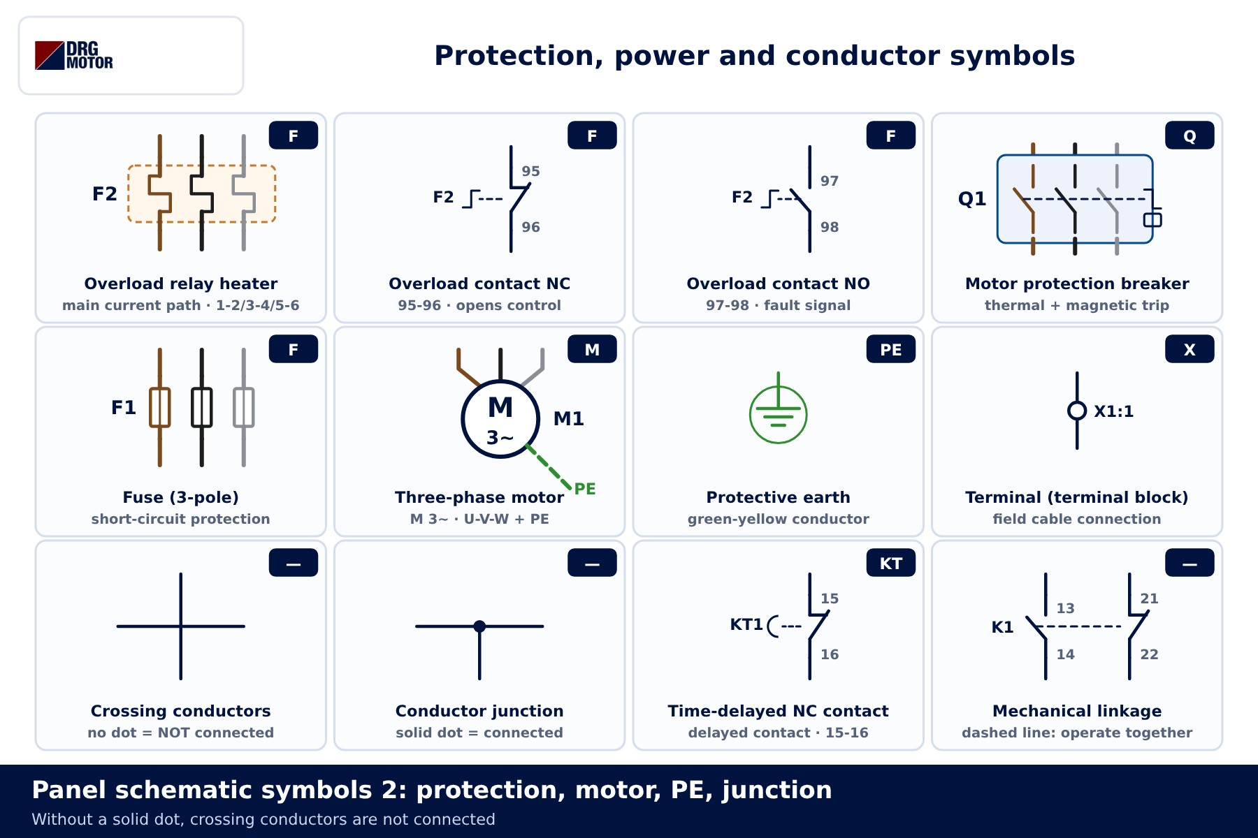
The overload relay appears in two places. Its heater sits in the power circuit and carries motor current; its 95-96 NC contact sits in the control circuit and cuts the contactor coil supply on overload. If the relay has a 97-98 NO contact, it usually lights the fault lamp. A motor protection breaker combines thermal and magnetic trips in one housing; the article on thermal relay vs motor protection breaker covers the difference in detail.
The detail people miss most often is the conductor crossing. A solid dot means the conductors are connected; without a dot the lines simply cross and there is no electrical connection. An installer who overlooks this can join two separate lines on the terminal block.
What is the difference between NO and NC contacts?
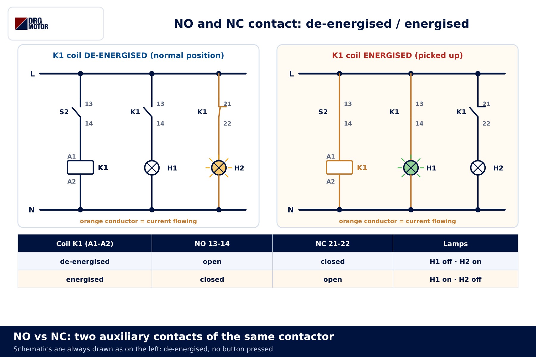
The same contactor can carry both NO and NC auxiliary contacts, and both move with the same coil. In the drawing below a lamp is wired to K1's 13-14 (NO) and 21-22 (NC) contacts. The left side shows the coil de-energised, the right side energised; the conductor carrying current is drawn in orange.
| K1 coil | NO 13-14 | NC 21-22 | Result |
|---|---|---|---|
| De-energised (normal) | Open | Closed | H1 off, H2 on |
| Energised (picked up) | Closed | Open | H1 on, H2 off |
The rule is simple: the drawing always shows the de-energised state. When the coil picks up, every NO contact closes and every NC contact opens; when it drops out, they all return to the drawn position. For push-buttons, read "pressed" instead of "energised" and the logic is the same.
How do you read terminal numbers?
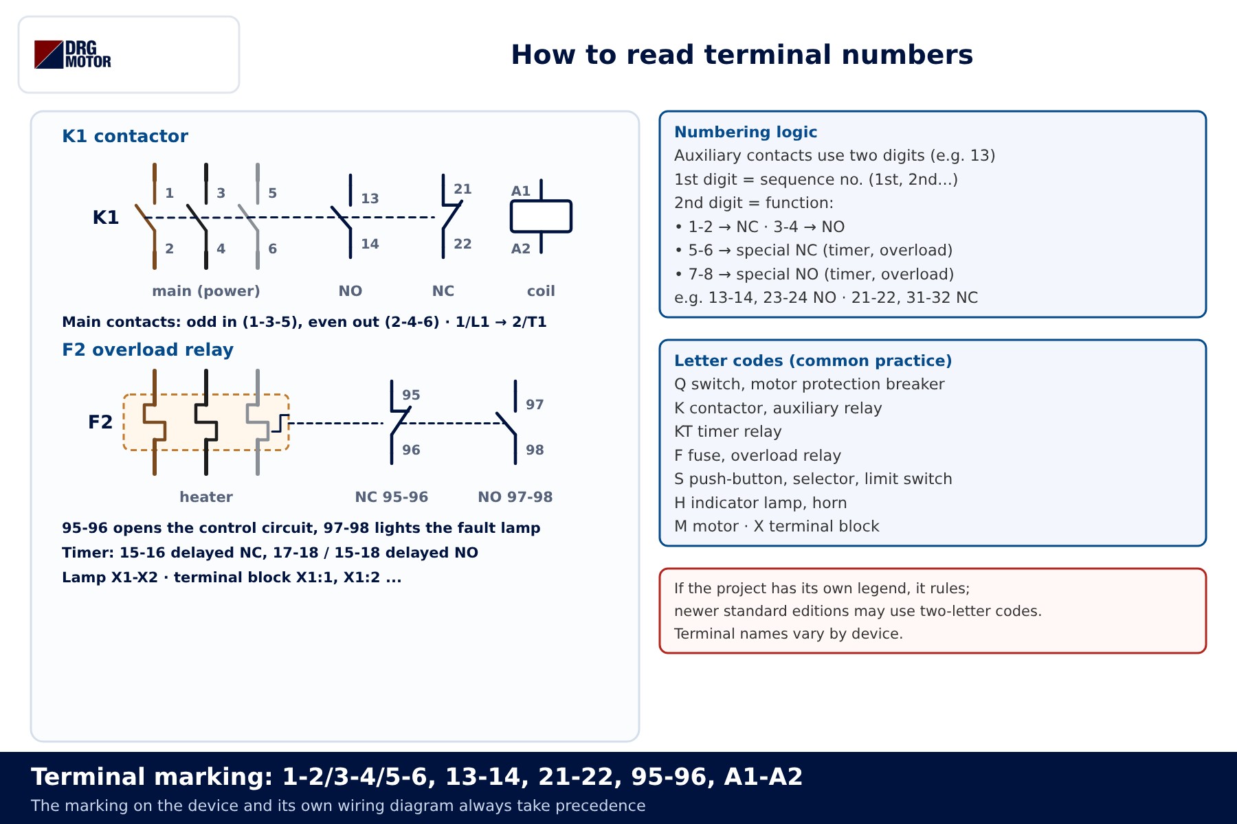
The numbers printed on contactors, overload relays and relays follow a pattern. On main contacts the inputs are odd (1, 3, 5) and the outputs even (2, 4, 6). Auxiliary contacts use two digits: the first gives the sequence number, the second the function.
| Second digit | Meaning | Example |
|---|---|---|
| 1-2 | NC (normally closed) | 21-22, 31-32 |
| 3-4 | NO (normally open) | 13-14, 43-44 |
| 5-6 | Special-function NC (overload, timer) | 95-96, 15-16 |
| 7-8 | Special-function NO (overload, timer) | 97-98, 17-18 |
So 13-14 means "first contact, NO" and 21-22 means "second contact, NC". The overload relay's 95-96 and 97-98 and the coil's A1-A2 are named variants of the same scheme. Terminal names vary by device; the marking on the device and its own wiring diagram take precedence. For sizing, see motor panel contactor selection and the overload, fuse and contactor selection tool.
Reading the sample schematic step by step
Now let's put the symbols together. On the left is the power circuit (Q1, K1, F2, M1); on the right the 230 V AC control circuit (F3, F2 95-96, S0, S2, K1 self-holding, lamps H1 and H2).
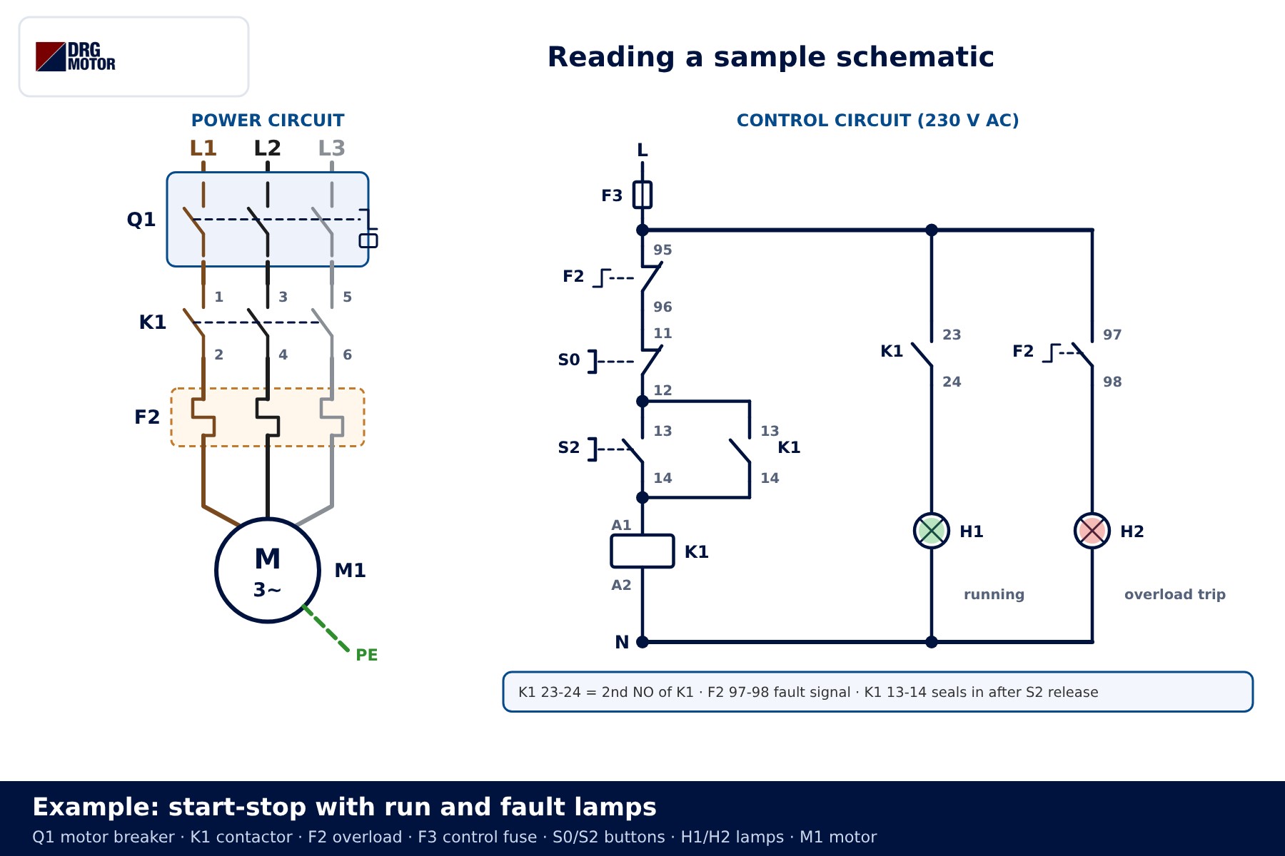
- Starting point: Q1 is closed and the motor is stopped. F2 95-96 and S0 are closed; S2 and K1 13-14 are open, so the K1 coil has no voltage.
- S2 is pressed: current flows from the L rail through F3, F2 95-96, S0 and S2 to the K1 coil. K1 picks up and its main contacts connect the motor to the supply.
- Self-holding: K1 13-14 closes and forms a path in parallel with S2. When S2 is released, the coil stays energised through this path.
- Run lamp: K1's second NO contact, 23-24, also closes and H1 lights.
- S0 is pressed: the series path breaks, K1 drops out and 13-14 opens; the motor stops and does not restart when S0 is released.
- Overload trips: F2 95-96 opens and drops K1; at the same time 97-98 closes and the H2 fault lamp lights. The motor cannot restart until the relay is reset, manually or automatically.
The overload relay is set from the rated current on the motor nameplate; the motor current chart gives a starting figure, but the nameplate value is what counts. Forward-reverse circuits use the same NC logic to interlock the opposite contactor; see three-phase motor forward-reverse wiring.
Common mistakes when reading a schematic
| Symptom | Likely cause |
|---|---|
| Motor stops as soon as the start button is released | Self-holding contact wired to the NC terminals (21-22), or missing |
| When the coil picks up, a lamp goes out instead of lighting | Lamp wired to an NC contact instead of an NO contact |
| Motor keeps running after the overload trips | 97-98 wired in series with the control line instead of 95-96 |
| Control fuse blows as soon as the circuit is switched on | A crossing without a dot has been joined on the terminal block |
| Stop button does not stop the motor | The NO block (13-14) of the stop button was used |
| Contactor hums but does not pull in | Coil voltage does not match the control voltage; check the A1-A2 rating |
Most of these faults are avoided by checking every terminal number on site against the drawing before commissioning.
Send a photo of your current motor nameplate and we will find the suitable DRG model together.Send on WhatsApp
DRG motors used with this type of panel
DRG Motor is an electric motor manufacturer, supplier and seller. Below are a few three-phase models from the power range often found on direct-on-line start-stop panels. Contactors, overload relays, push-buttons and lamps are not sold by DRG; please ask your panel component supplier. All options are listed on the three-phase asynchronous electric motors page and in the online store.
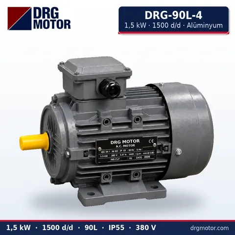
1.5 kW Three-Phase Motor 1500 rpm – DRG-90L-4 Aluminium
- 1.5 kW · 1500 rpm (4 poles)
- Aluminium frame · IEC 90L
- Mounting: B3 · B5 · B14 · B35
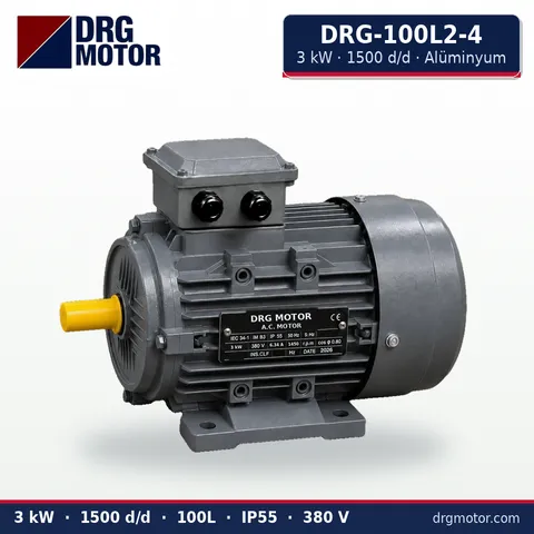
3 kW Three-Phase Motor 1500 rpm – DRG-100L2-4 Aluminium
- 3 kW · 1500 rpm (4 poles)
- Aluminium frame · IEC 100L
- Mounting: B3 · B5 · B14 · B35
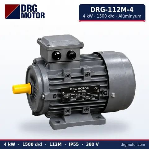
4 kW Three-Phase Motor 1500 rpm – DRG-112M-4 Aluminium
- 4 kW · 1500 rpm (4 poles)
- Aluminium frame · IEC 112M
- Mounting: B3 · B5 · B14 · B35
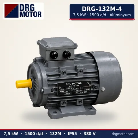
7.5 kW Three-Phase Motor 1500 rpm – DRG-132M-4 Aluminium
- 7.5 kW · 1500 rpm (4 poles)
- Aluminium frame · IEC 132M
- Mounting: B3 · B5 · B14 · B35
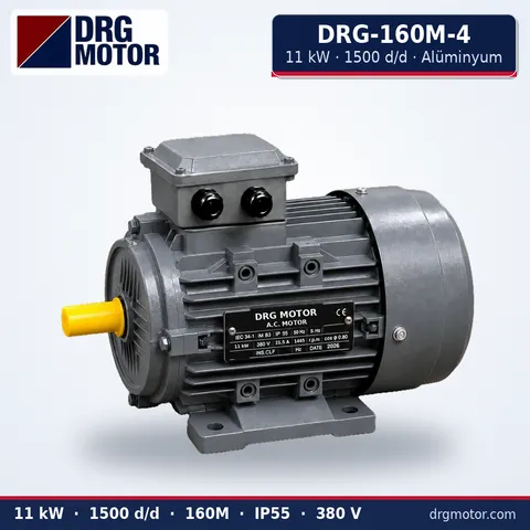
11 kW Three-Phase Motor 1500 rpm – DRG-160M-4 Aluminium
- 11 kW · 1500 rpm (4 poles)
- Aluminium frame · IEC 160M
- Mounting: B3 · B5 · B14 · B35
Click to see current prices for these motors and order nowSEE PRICES →
Frequently asked questions
How can I tell an NO from an NC contact with a meter?
With the supply isolated and verified dead, set the meter to continuity. On a de-energised contactor the NC contact (21-22) conducts and the NO contact (13-14) does not. Pressing the contactor's manual test button reverses both.
Why are contacts drawn open or closed instead of in their real state?
Because a schematic shows devices de-energised, with no button pressed and the machine in its rest position. To find the running state, follow which coils are energised and mentally flip their contacts.
Can I use 43-44 instead of 13-14?
Both are NO contacts; only the sequence number differs. Use whichever the drawing shows, and if you change it on site, update the drawing too.
Do the overload relay's 95-96 and 97-98 change at the same time?
Yes, both are driven by the same mechanism. On a trip 95-96 opens and 97-98 closes; after reset both return to their normal position.
📄 Download Wiring Diagram PDF A4 printable PDF of the diagrams and tables (no sign-up)





