 English
 Le français
 Türkçe





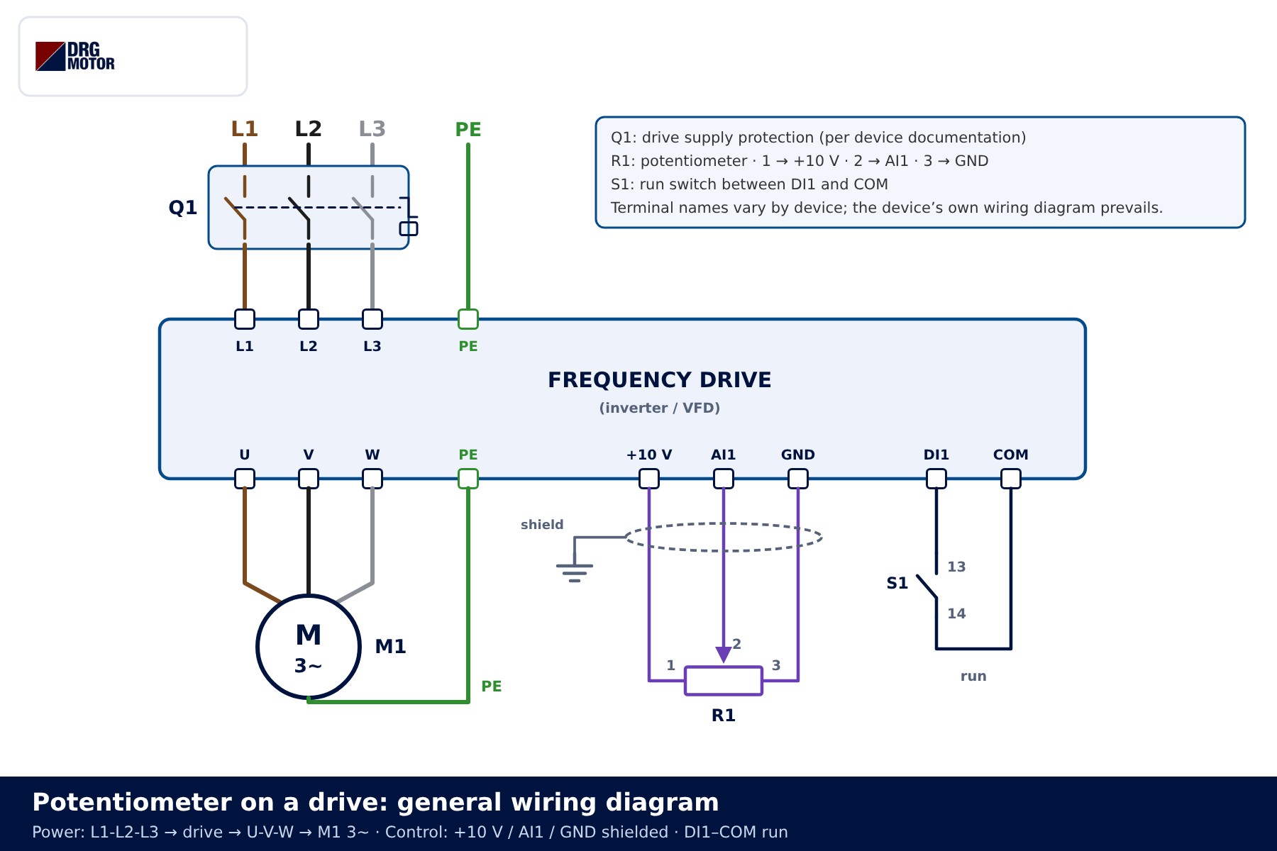
A potentiometer is wired to a drive with three wires: one end goes to the drive’s +10 V reference output, the other end to 0 V (GND/COM), and the middle pin – the wiper – to analog input AI1. The drive turns the 0–10 V wiper voltage into a frequency reference, and motor speed rises roughly in proportion to the frequency. For this to work, AI1 must be set to voltage and selected as the frequency reference source.
Safety notice: This content is for technical information only. Wiring, measurement and commissioning must be carried out by qualified electrical personnel, following lock-out and verification of de-energised state, and in line with the motor and device manufacturer's documentation.
This article draws the connection step by step: general diagram, the three pot terminals, the shielded cable, voltage/current selection, the frequency–speed relationship, changing direction and a parameter checklist. Terminal names vary by device; the device’s own wiring diagram prevails. For what a drive is and how the terms inverter and frequency converter differ, see frequency converter vs inverter.
General wiring: power side and control side
The diagram has two separate worlds. On the power side, mains L1-L2-L3 reach the drive input through a protective device (Q1), and the drive’s U-V-W output goes straight to the motor; the PE conductor is bonded to both the drive and the motor frame. No contactor, overload relay or star-delta arrangement sits between drive and motor – the drive protects the motor through its own parameters. The control side carries signals of a few milliamps: the pot goes to +10 V / AI1 / GND and the run switch between DI1 and COM.
| Item / terminal | Connected to | Function |
|---|---|---|
| R1 pot, pin 1 | +10 V reference output | Top end of the voltage divider |
| R1 pot, pin 2 (wiper) | AI1 analog input | 0–10 V signal following the knob |
| R1 pot, pin 3 | 0 V / GND / COM (analog common) | Bottom end of the voltage divider |
| Cable shield | Shield clamp / PE at the drive | Reduces noise pick-up on the signal |
| Run switch | DI1 – COM | Gives the drive its run command |
| Q1 protection | Drive supply L1-L2-L3 | Protects the supply cable and the drive |
The links in the motor terminal box follow the drive’s output voltage: with a 400 V output drive, a 230/400 V motor is connected in star and a 400/690 V motor in delta. The logic is explained in what is a star-delta connection, and the 230 V supply case in motor selection for a 220 V inverter.
How are the three pot terminals connected?
A potentiometer is a voltage divider. The drive’s own +10 V reference is applied across its two outer pins; as the knob turns, the middle pin (wiper) moves between those two levels. Fully anticlockwise gives about 0 V at AI1, mid position about 5 V, fully clockwise about 10 V.
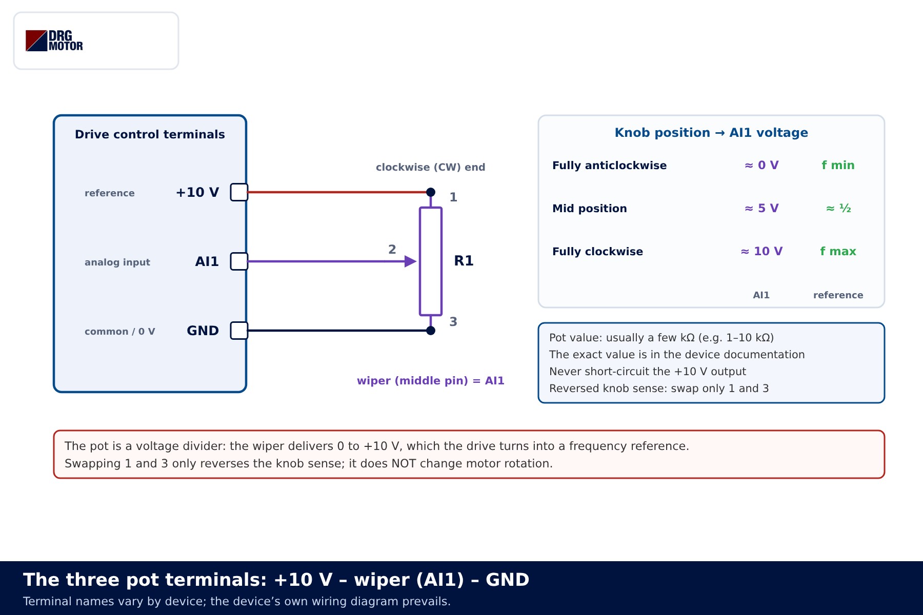
- Pin 1 → +10 V: the drive’s reference output; no external supply is needed.
- Pin 2 (wiper) → AI1: the only wire carrying the speed information. Being the middle leg it is hard to mix up, but confirm it with a meter.
- Pin 3 → 0 V / GND: the analog common. Some devices keep the digital common (COM) separate from the analog common; use the analog one for the pot.
A common pot value is a few kΩ (for example 1–10 kΩ); the exact value and the lowest permitted value are in the device documentation. Too low a value overloads the +10 V output, too high a value makes the signal more sensitive to noise. A linear-taper pot gives an even relationship between knob position and speed.
📄 Download Wiring Diagram PDF A4 printable PDF of the diagrams and tables (no sign-up)
Click to see current electric motor prices and order nowSEE PRICES →
Shielded cable and shield earthing
The drive output switches at high frequency, and a signal cable running near the motor cable picks up that noise easily. The pot cable is therefore a three-core shielded (screened) cable, with all three conductors inside the same sheath.
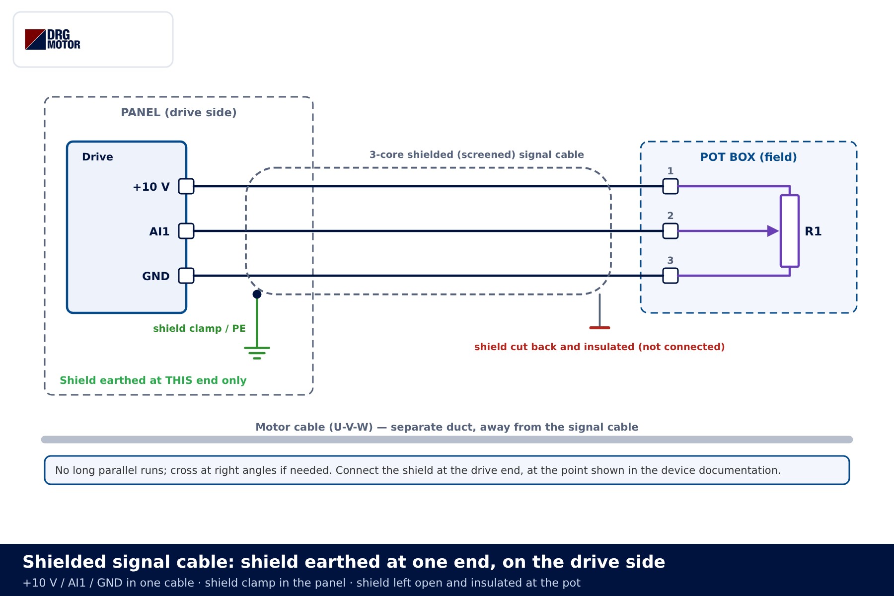
The shield is earthed at one end only, on the drive side: in the panel it goes to the shield clamp or the earth point shown in the device documentation. At the pot box the shield is cut back, insulated and left unconnected. A shield earthed at both ends can carry earth-loop current and create exactly the speed hunting you are trying to avoid. Keep the signal cable out of the motor cable duct; where they must cross, cross at right angles. Motor cable size is a separate topic – the motor cable size calculator gives a starting value.
Analog input: voltage or current?
On many drives AI1 accepts either a voltage (0–10 V) or a current (0/4–20 mA) signal. The choice is made in two places: a small switch or jumper on the board, and a parameter. A potentiometer is always a voltage source, so the selector must be in the “U” position and the parameter set to voltage. Current mode is meant for 4–20 mA transmitters such as pressure, level or temperature transmitters.
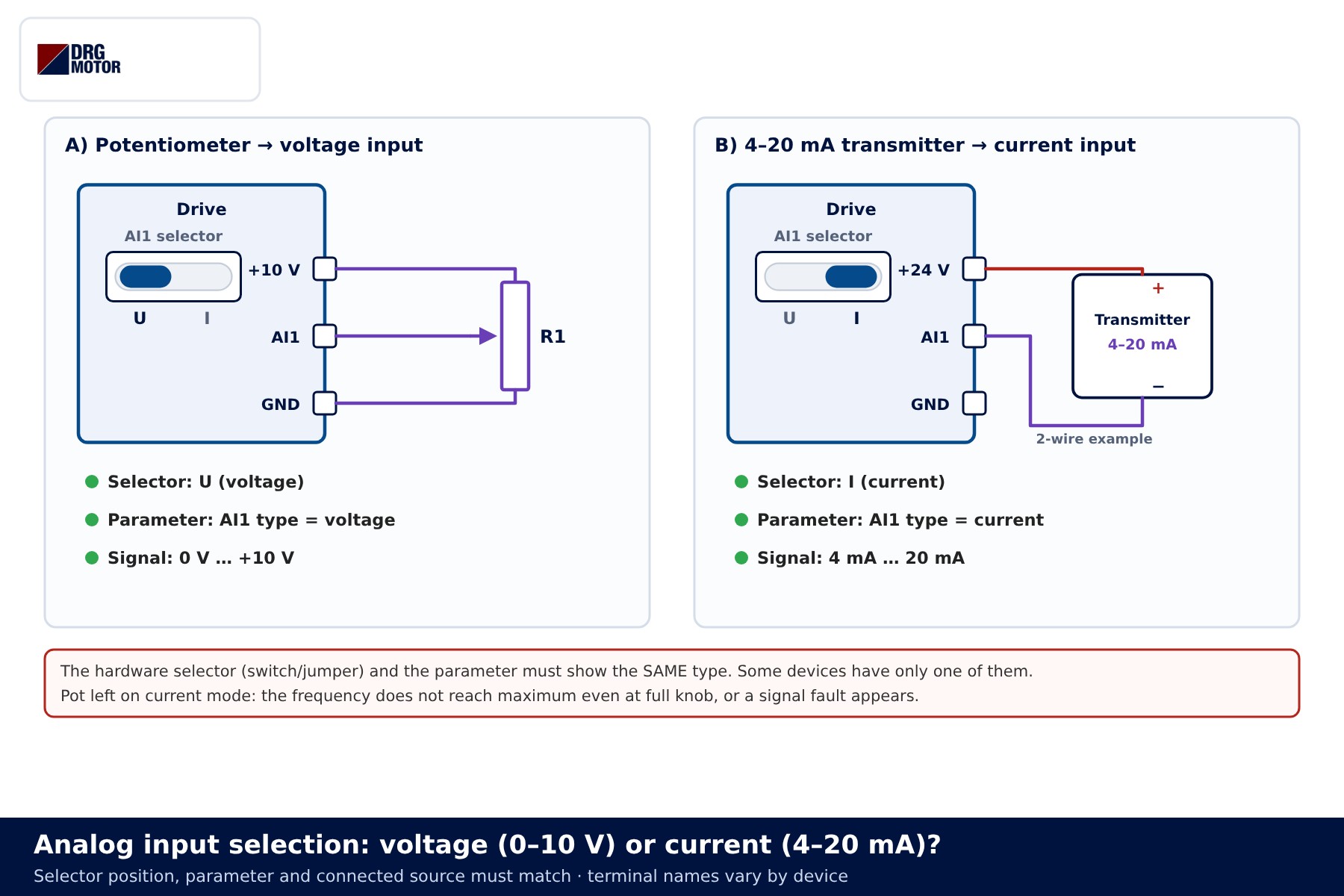
When selector and parameter disagree, the usual symptom is that the frequency never reaches maximum even with the pot fully up, or the drive reports a signal fault. Some devices have only the parameter, others only the hardware selector; the device documentation prevails.
Frequency reference and motor speed
The drive maps the AI1 voltage linearly to frequency. In the most common set-up, 0 V corresponds to minimum frequency and 10 V to maximum frequency. The synchronous speed of an induction motor is ns = 120 × f / p (p = number of poles). A 4-pole motor has a synchronous speed of 1500 rpm at 50 Hz and 750 rpm at 25 Hz. Actual shaft speed is slightly lower by the load-dependent slip, which is why the relationship is described as approximately proportional.
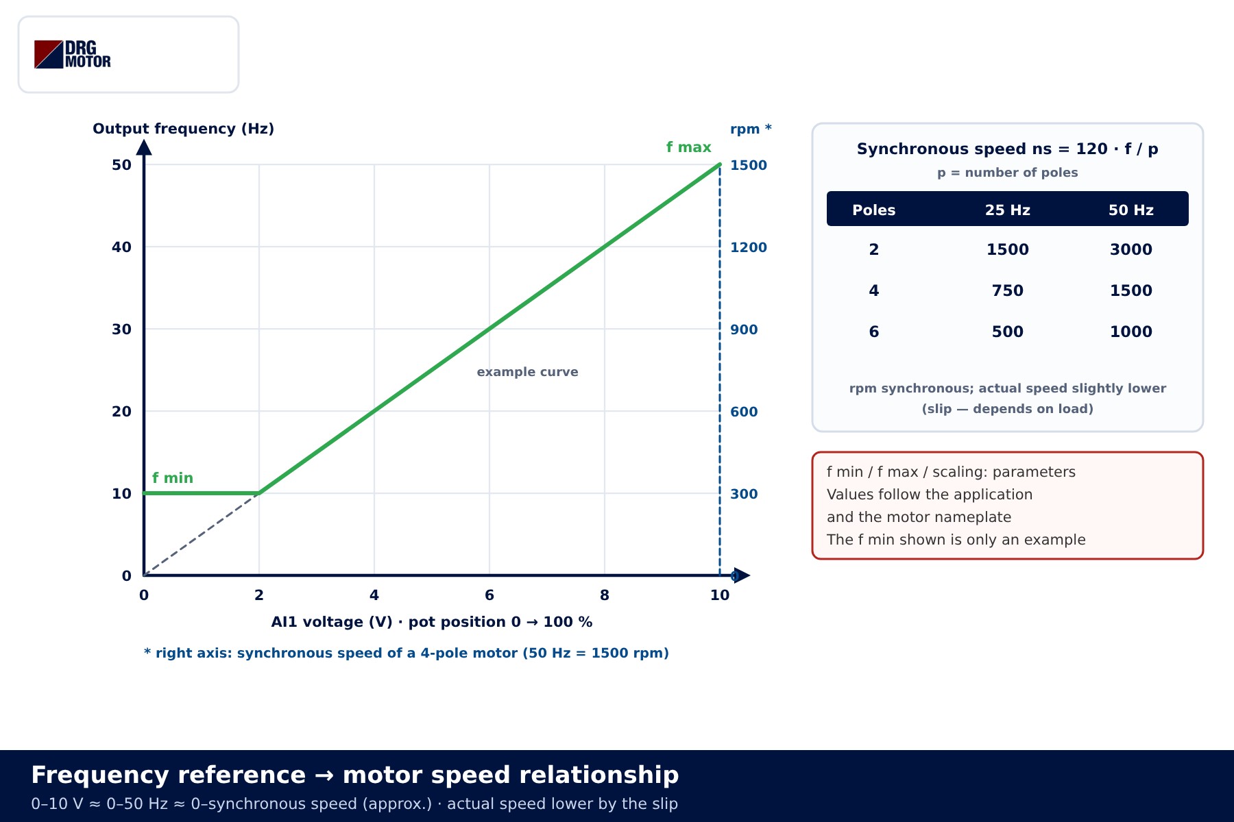
If minimum frequency is set above zero, the start of the curve flattens: the motor runs at that frequency even with the pot at zero. That is a setting, not a fault. At low speed the motor’s own fan moves less air, so cooling must be reviewed for applications running loaded at low speed for long periods – see insulation and forced cooling for VFD motors. To work out shaft speeds with different pulleys and speeds, use the electric motor calculator.
Motor runs backwards: use the command, not the pot ends
The pot only sets the size of the speed; it carries no direction information. Swapping pins 1 and 3 leaves the motor turning the same way – the knob simply works backwards, speeding up when turned left. Playing with the wrong pins also risks short-circuiting the +10 V output.
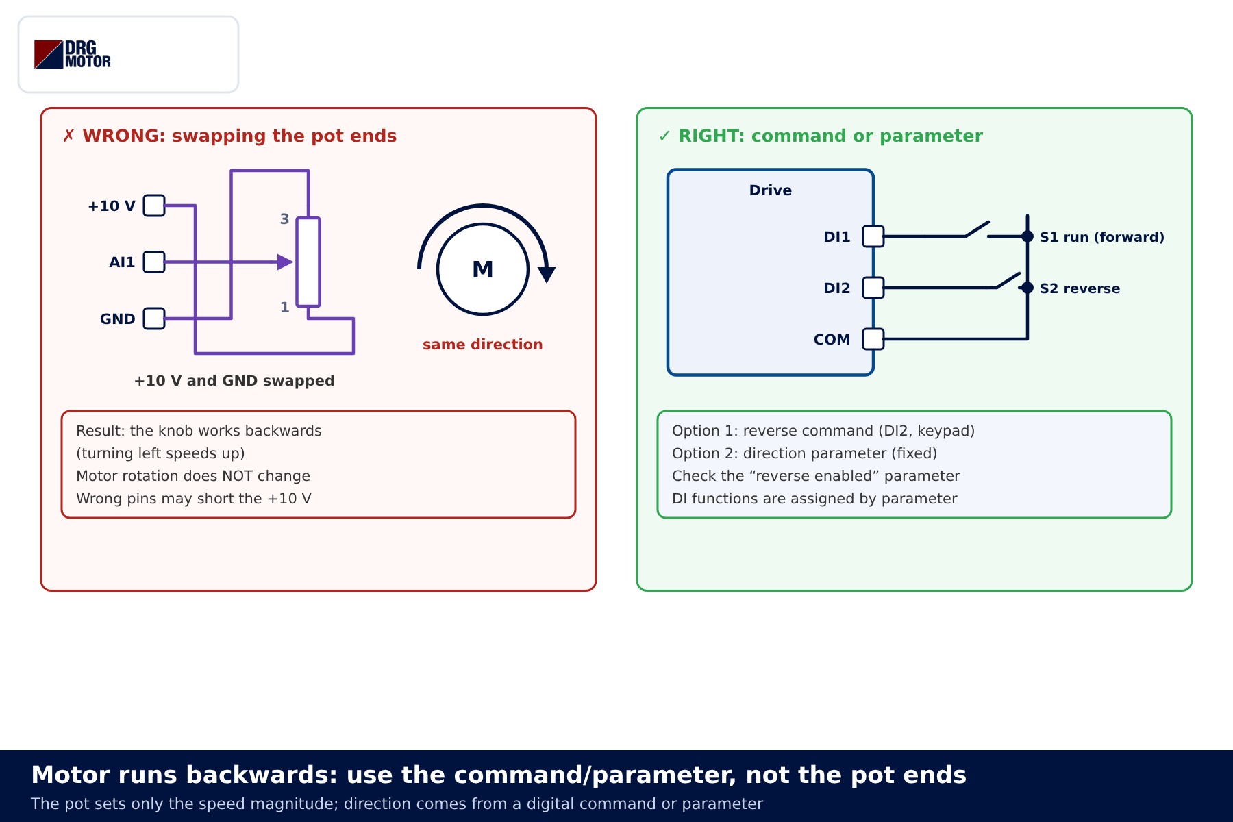
There are two correct ways to change direction: assign a “reverse” function to a digital input (DI2 in the example), or select a fixed direction by parameter. Some devices also need a separate reverse-enable parameter. Direction changes in circuits without a drive are covered in why an electric motor runs backwards; on a drive system, using the parameter rather than swapping two motor phases keeps the commissioning records consistent.
Parameter checklist
The list below gives no values; it sets out which groups to check. Values come from the device documentation, the motor nameplate and the needs of the machine.
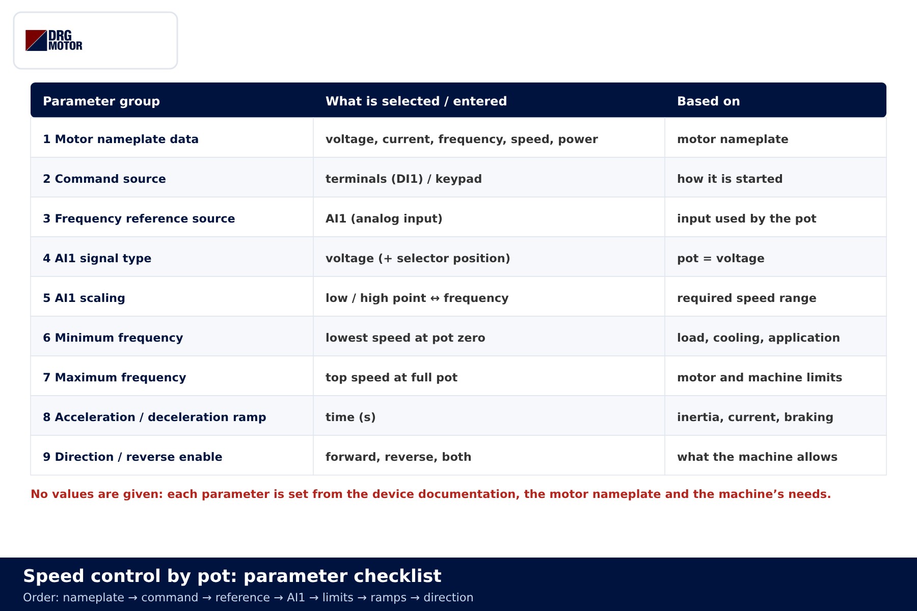
| Parameter group | What to set | Based on |
|---|---|---|
| Motor nameplate data | voltage, current, frequency, speed, power | motor nameplate |
| Command source | terminals (DI1) or keypad | how the motor is started |
| Frequency reference source | AI1 | the input the pot is wired to |
| AI1 signal type and scaling | voltage; low/high point ↔ frequency | pot and required speed range |
| Minimum / maximum frequency | lowest and highest speed | load, cooling, motor and machine limits |
| Acceleration / deceleration ramp | time | inertia, current, braking needs |
| Direction / reverse enable | forward, reverse or both | what the machine allows |
Short ramp times can mean high current on starting and a rising DC-bus voltage on stopping. For high-inertia loads that will not slow down cleanly, see inverter dynamic braking and braking resistor.
Common wiring and setting mistakes
| Symptom | Likely cause |
|---|---|
| Motor runs at the same speed whatever the knob does | Reference source still keypad or preset speed; AI1 not selected |
| Pot fully up, frequency stops halfway | AI1 set to current, wrong scaling, or maximum frequency set low |
| Knob works backwards (turning left speeds up) | Pins 1 and 3 swapped; motor direction is not affected |
| Speed drifts or hunts on its own | Unshielded cable, shield earthed at both ends, or signal cable in the motor cable duct |
| Drive trips or +10 V collapses when the pot is fitted | Wiper wired to GND or +10 V; pot value far below the recommended one |
| Motor still turns with the pot at zero | Minimum frequency set above zero — a setting, not a fault |
Measurement tip: with the supply on and the motor stopped, measure between AI1 and GND. If the voltage moves smoothly from 0 to close to 10 V as the knob turns, the wiring is right and the problem is in the parameters.
📄 Download Wiring Diagram PDF A4 printable PDF of the diagrams and tables (no sign-up)
Send a photo of your current motor nameplate and we will find the suitable DRG model together.Send on WhatsApp
DRG motors for speed control with a drive
DRG Motor is an electric motor manufacturer, supplier and seller. The three-phase IEC motors below fall in the power range often used for pot-controlled conveyors, fans, mixers and similar machines. Drives, potentiometers and control components are not sold by DRG; please contact your panel component supplier or the device manufacturer. Other ratings and speeds are listed under three-phase asynchronous electric motors and in the online store; rated currents are in the motor current chart.
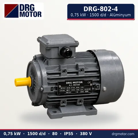
0.75 kW Three-Phase Motor 1500 rpm – DRG-802-4 Aluminium
- 0.75 kW · 1500 rpm (4 poles)
- Aluminium frame · IEC 80
- Mounting: B3 · B5 · B14 · B35
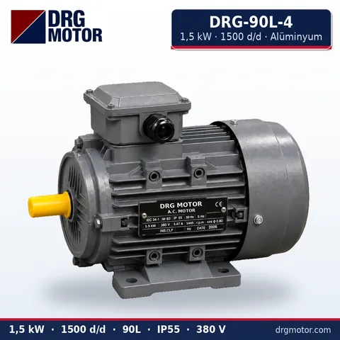
1.5 kW Three-Phase Motor 1500 rpm – DRG-90L-4 Aluminium
- 1.5 kW · 1500 rpm (4 poles)
- Aluminium frame · IEC 90L
- Mounting: B3 · B5 · B14 · B35
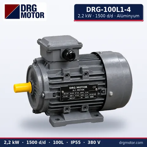
2.2 kW Three-Phase Motor 1500 rpm – DRG-100L1-4 Aluminium
- 2.2 kW · 1500 rpm (4 poles)
- Aluminium frame · IEC 100L
- Mounting: B3 · B5 · B14 · B35
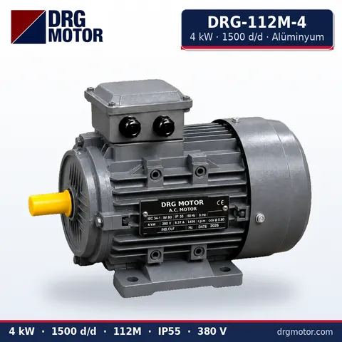
4 kW Three-Phase Motor 1500 rpm – DRG-112M-4 Aluminium
- 4 kW · 1500 rpm (4 poles)
- Aluminium frame · IEC 112M
- Mounting: B3 · B5 · B14 · B35
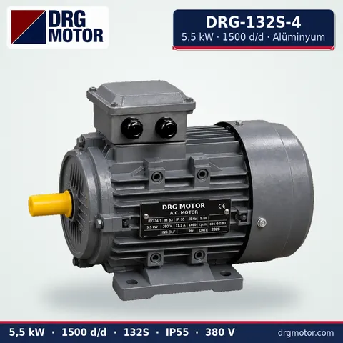
5.5 kW Three-Phase Motor 1500 rpm – DRG-132S-4 Aluminium
- 5.5 kW · 1500 rpm (4 poles)
- Aluminium frame · IEC 132S
- Mounting: B3 · B5 · B14 · B35
Click to see current prices for these motors and order nowSEE PRICES →
Frequently asked questions
What pot value should be used on a drive?
A common range is a few kΩ (for example 1–10 kΩ). The current available from the +10 V output and the recommended pot value are given in the device documentation; take the exact value from there.
The pot is fully up but the motor does not reach 50 Hz – why?
The usual causes are AI1 left in current mode, a wrong high scaling point or a low maximum frequency. First measure AI1–GND to confirm the signal approaches 10 V.
Would earthing the shield at both ends be better?
For analog signal cables the usual practice is to earth the shield at the drive end only. A shield earthed at both ends can carry earth-loop current and cause speed hunting. If the device documentation describes a different method, follow it.
Can I reverse the pot wires to change direction?
No. Reversing the pot ends only changes how the knob works. Motor direction is changed with a reverse command or the direction parameter.
Why doesn’t the motor stop completely with the pot at zero?
The minimum frequency parameter may be above zero. To stop the motor, remove the run command; the pot is for setting speed, not for stopping.





