 English
 Le français
 Türkçe

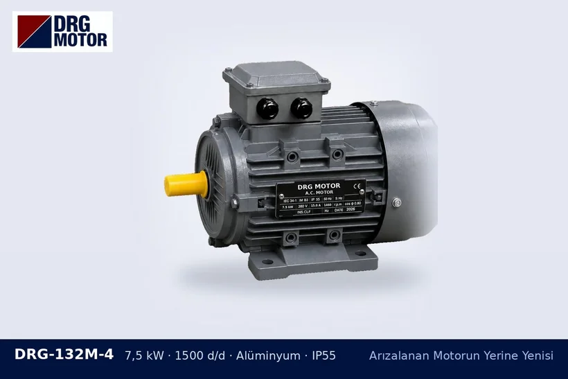
The same power and the same IEC frame number do not on their own guarantee that the motor will fit into a tight space. The mounting dimensions (H, shaft, foot holes) are standardised; however, the overall length, frame diameter, terminal box height and the clearance behind the fan cover can vary from model to model.
What to measure at the installation
- The distance from the shaft shoulder to the obstacle behind the motor (compared with the L value of the new motor)
- The free height above the frame; the terminal box sits in this area
- The side from which the cable can enter, and its bending radius
- The gap between the fan cover and the wall or guard
Some values from the DRG catalogue give an idea:
| Model | Frame | Shaft D×E (mm) | Overall length L (mm) |
|---|---|---|---|
| DRG-112M-4 | 112M | 28×60 | 394 |
| DRG-132M-4 | 132M | 38×80 | 476 |
| DRG-160M-4 | 160M | 42×110 | 608 |
Do not forget the cooling air
DRG motors are of type IC411: the fan at the rear draws air in through the cover and blows it along the frame fins. If the fan cover is pressed against a wall, the motor is under-cooled and the winding heats up. Inadequate ventilation is among the conditions excluded from the warranty, so leave clearance on the fan side for the air intake.
Ease of removal and fitting
In the 0.25–11 kW range, aluminium frame models are lighter than cast iron models of the same power; in enclosed areas where lifting by hand is difficult, this difference can make the job easier. With flange mounting (B5/B35), the motor must be able to be withdrawn along its axis; check that there is enough sliding allowance on the coupling side. Keeping the nameplate readable and the terminal box on the accessible side makes later maintenance easier.
After comparing dimensions on the motor technical drawings, you can look at the aluminium frame motor family or the page of the 7.5 kW 1500 rpm DRG-132M-4 aluminium model.