 English
 Le français
 Türkçe





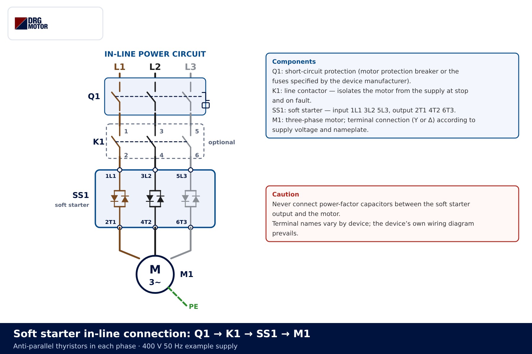
A soft starter is wired in series with the motor supply (in-line): the mains pass through Q1 short-circuit protection and an optional K1 line contactor into the device inputs 1L1 3L2 5L3, and from outputs 2T1 4T2 6T3 to the motor. When the start ramp ends, bypass contacts (inside the device or an external contactor KB) short the thyristors and the motor runs at full voltage through the contacts. At stop the order reverses: the bypass opens first and, if selected, the thyristors perform a stop ramp.
Safety: This content is for technical information only. Wiring, measurement and commissioning must be carried out by qualified electrical personnel, following lock-out and verification of de-energised state, and in line with the motor and device manufacturer's documentation.
This article covers wiring and control. For a comparison of starting methods see Star-delta vs soft starter; for conventional starter circuits see the star-delta connection diagram guide.
In-line soft starter power circuit
In the in-line arrangement every phase of the device holds a pair of anti-parallel thyristors. The firing angle is advanced during the start, so the motor voltage rises from a low value towards full mains voltage. The motor terminal connection does not change: on a 400 V supply a 230/400 V motor is connected in star and a 400/690 V motor in delta, and the soft starter feeds the three leads.
| Item | Function | Note |
|---|---|---|
| Q1 | Short-circuit and overcurrent protection | Motor protection breaker or the fuse type required by the device manufacturer |
| K1 (optional) | Line contactor; isolates the motor at stop and on fault | Thyristors do not provide galvanic isolation |
| SS1 | Soft starter: inputs 1L1 3L2 5L3, outputs 2T1 4T2 6T3 | Terminal names vary by device; the device’s own wiring diagram prevails |
| KB (if external bypass) | Shorts the thyristors at top of ramp | Connected to the terminals the device allows |
| M1 | Three-phase induction motor | Terminal connection per nameplate |
Even with the thyristors blocked, the motor is not isolated from the supply: a small leakage current and voltage at the terminals can be present. Isolate with Q1 before any work and confirm absence of voltage by measurement. Never fit power-factor capacitors between the soft starter output and the motor; if needed, they go on the supply side with their own contactor.
📄 Download Wiring Diagram PDF A4 printable PDF of the diagrams and tables (no sign-up)
Internal bypass versus external bypass contactor
A conducting thyristor has a voltage drop, which means heat in the panel. The bypass takes the current away from the thyristors once the start is complete and passes it through mechanical contacts. There are two ways to do this:
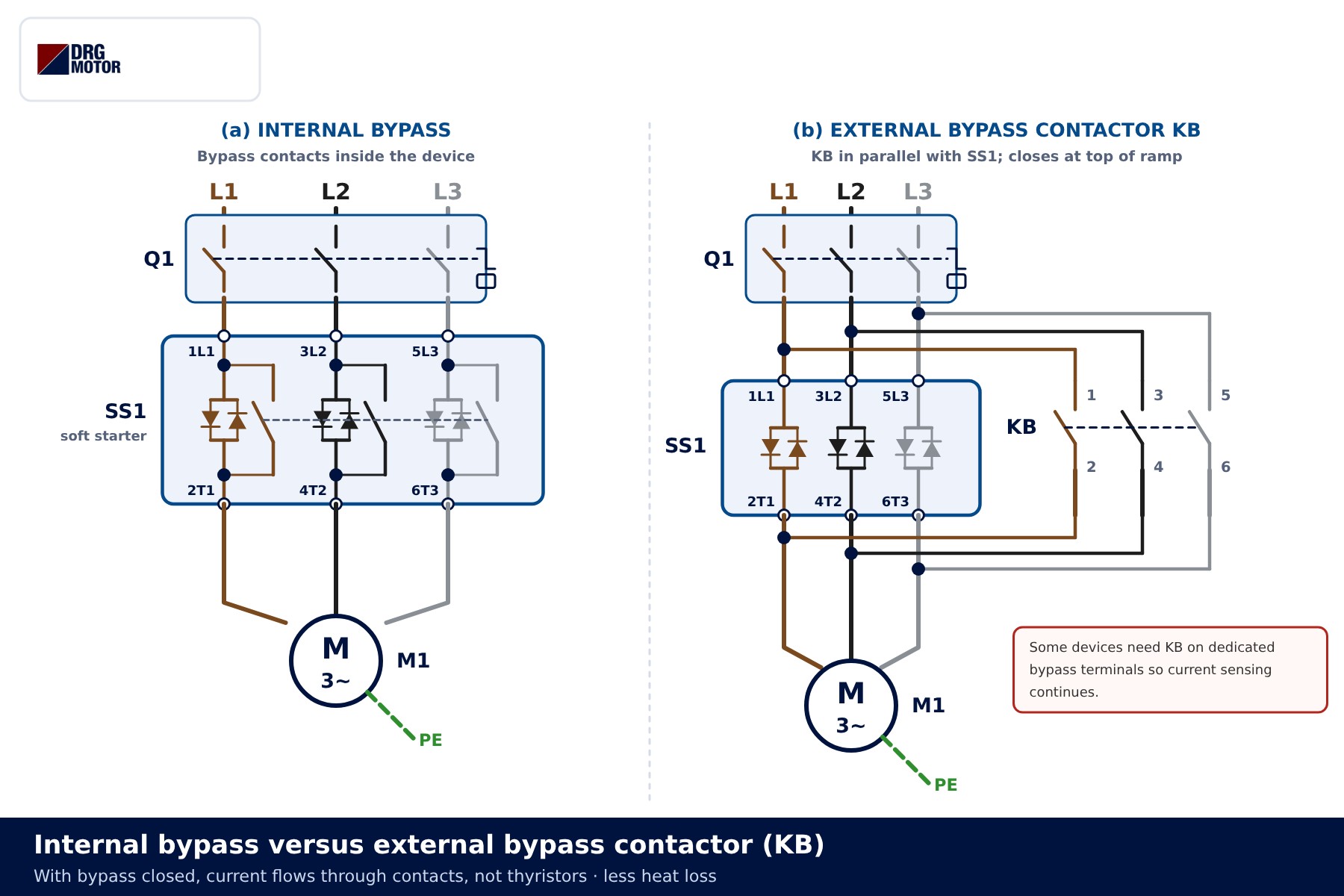
- Internal bypass: the contacts are built into the device, so no extra contactor or control wiring is needed. The panel stays compact and there is less room for wiring errors.
- External bypass contactor (KB): connected in parallel with SS1, taken from the input side (1L1 3L2 5L3) and the output side (2T1 4T2 6T3) with the same phase order. KB is energised by the device’s “top of ramp” relay. Some devices require KB on dedicated bypass terminals so that current sensing and electronic overload protection continue during bypass.
If the phase order of KB is mixed up, closing it creates a phase-to-phase short circuit. Take the upper and lower terminals of KB to terminals of the same phase on SS1 and check this before commissioning. KB is sized from the manufacturer’s table for the motor running current, not the starting current; our contactor selection article helps with this.
Click to see current electric motor prices and order nowSEE PRICES →
Control inputs and relay outputs
The example control circuit is 230 V AC, drawn as a vertical ladder. Stop button S0 and start button S2 latch run relay KA; a second KA contact links the START input to COM. Three relay outputs of the device manage the rest.
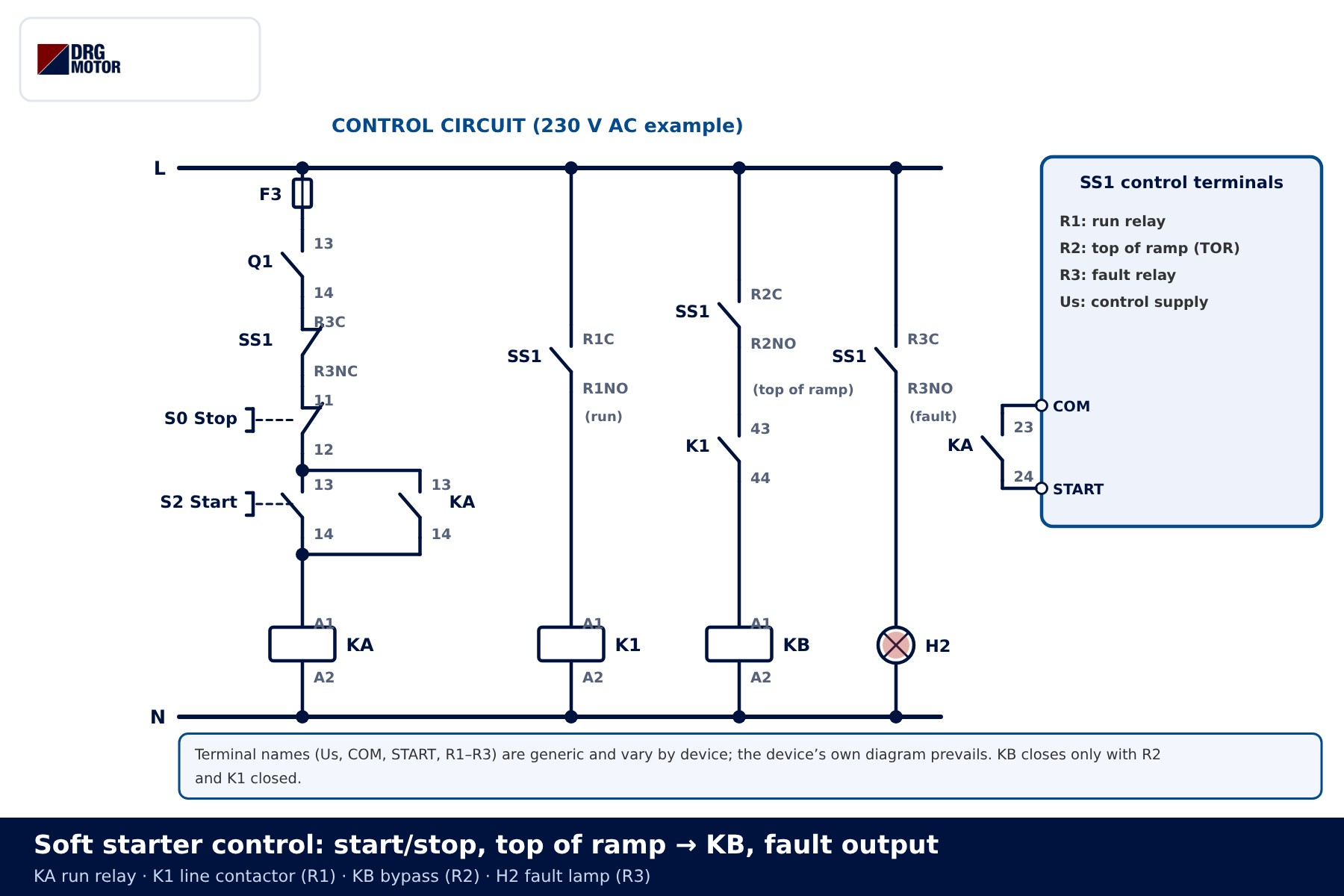
| Generic terminal | Function | Connected to (this diagram) |
|---|---|---|
| Us | Control supply | Voltage and terminal required by the device |
| START / COM | Run command (contact closed = run) | KA contact 23-24 |
| R1 (run) | Closes on command, opens after the stop ramp | K1 coil |
| R2 (top of ramp) | Closes when the motor reaches full voltage | In series with K1 43-44, KB coil |
| R3 (fault) | Changes state on fault | NC side in the KA line, NO side to lamp H2 |
Terminal names vary by device; the device’s own wiring diagram prevails. Some devices use separate start and stop inputs, others use 24 V DC digital inputs. Which relay acts as “run” and which as “top of ramp” is often chosen in the device menu. An emergency stop is not simply added to this stop chain like an ordinary button; the safety function is designed separately on the basis of a risk assessment.
Sequence of operation: from start to stop
- S2 pressed: KA picks up and holds through 13-14; contact 23-24 closes the START input.
- R1 closes: K1 picks up, SS1 is connected to the supply and the start ramp begins. Motor voltage rises from the set initial value; with current limit selected the device holds current at that limit.
- Ramp complete: R2 closes. As K1 43-44 is also closed, KB picks up and the thyristors are bypassed.
- S0 pressed: KA drops out and START opens. The device first opens R2, KB drops out and current returns to the thyristors.
- Stop ramp: if selected, voltage is reduced to slow the motor (used on pumps to limit water hammer). At the end R1 opens and K1 drops out. With coast stop the thyristors block at once.
- Fault: R3 changes over; its NC side drops KA and its NO side lights H2. K1 opens and the motor is disconnected.
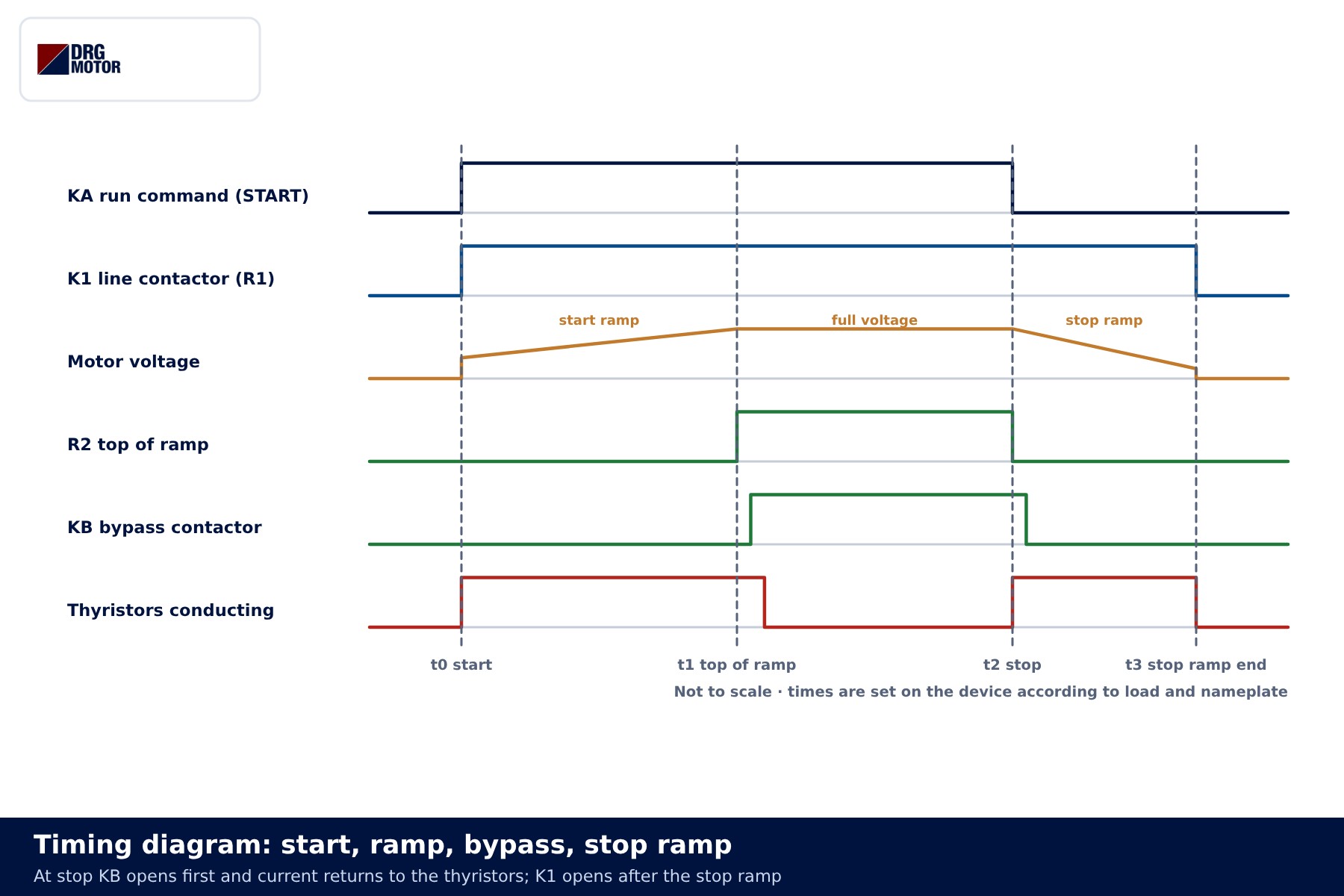
No figures are given here for ramp time, initial voltage or current limit; they are set at commissioning according to load inertia, the rated current on the motor nameplate and the device manufacturer’s guidance. Because motor torque falls with the square of voltage, too low an initial voltage can leave the motor unable to accelerate during the ramp.
State table
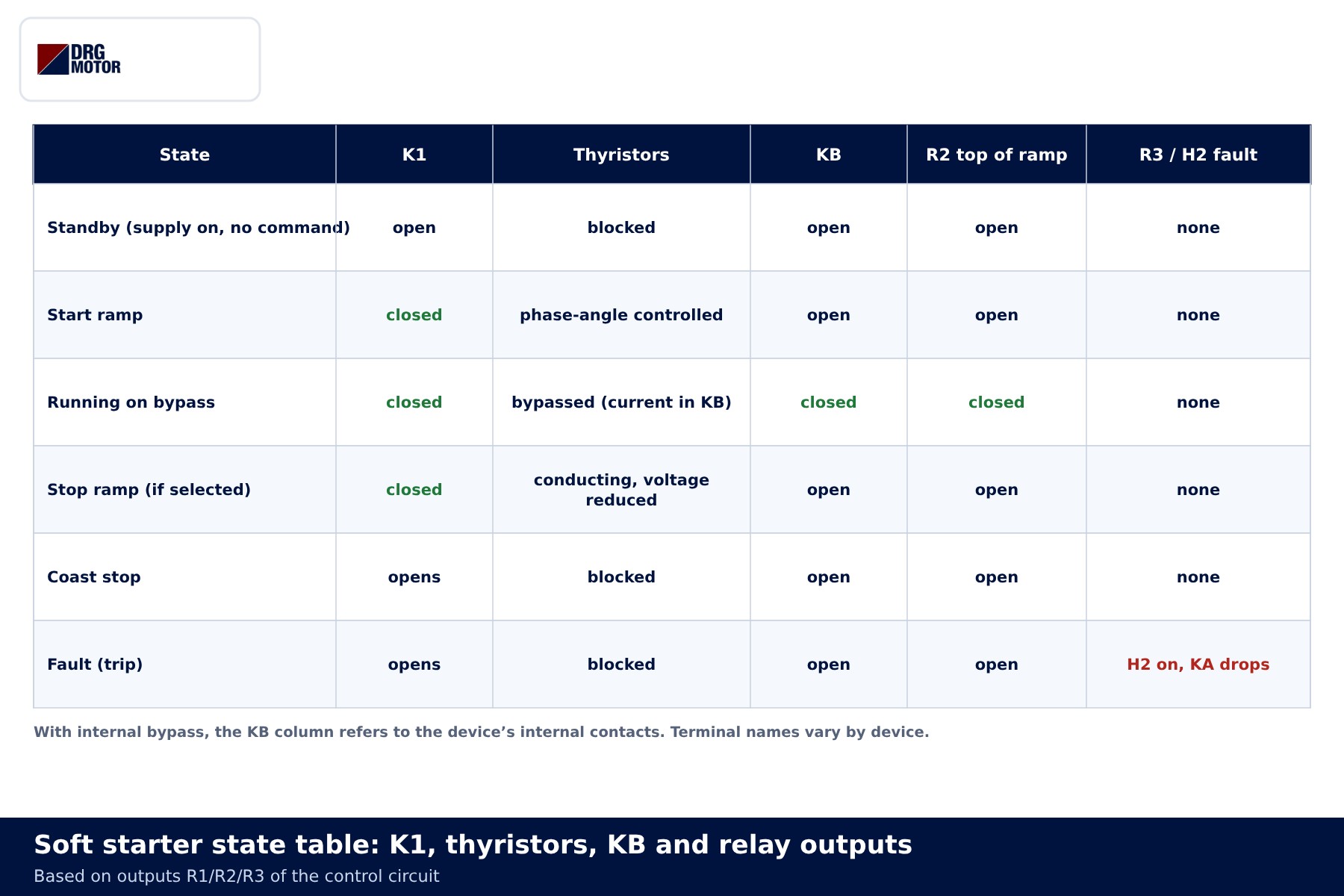
| State | K1 | Thyristors | KB |
|---|---|---|---|
| Standby | open | blocked | open |
| Start ramp | closed | phase-angle controlled | open |
| Running on bypass | closed | bypassed | closed |
| Stop ramp | closed | conducting at reduced voltage | open |
| Fault | opens | blocked | open |
Inside-delta connection: only if the manufacturer permits it
Some soft starters can be connected inside the delta of a 6-terminal motor. The terminal links are removed and one device pole is placed in series with each winding. The poles then carry winding current rather than line current, roughly 1/√3 of the line current, so a lower-rated device may be enough for the same motor.
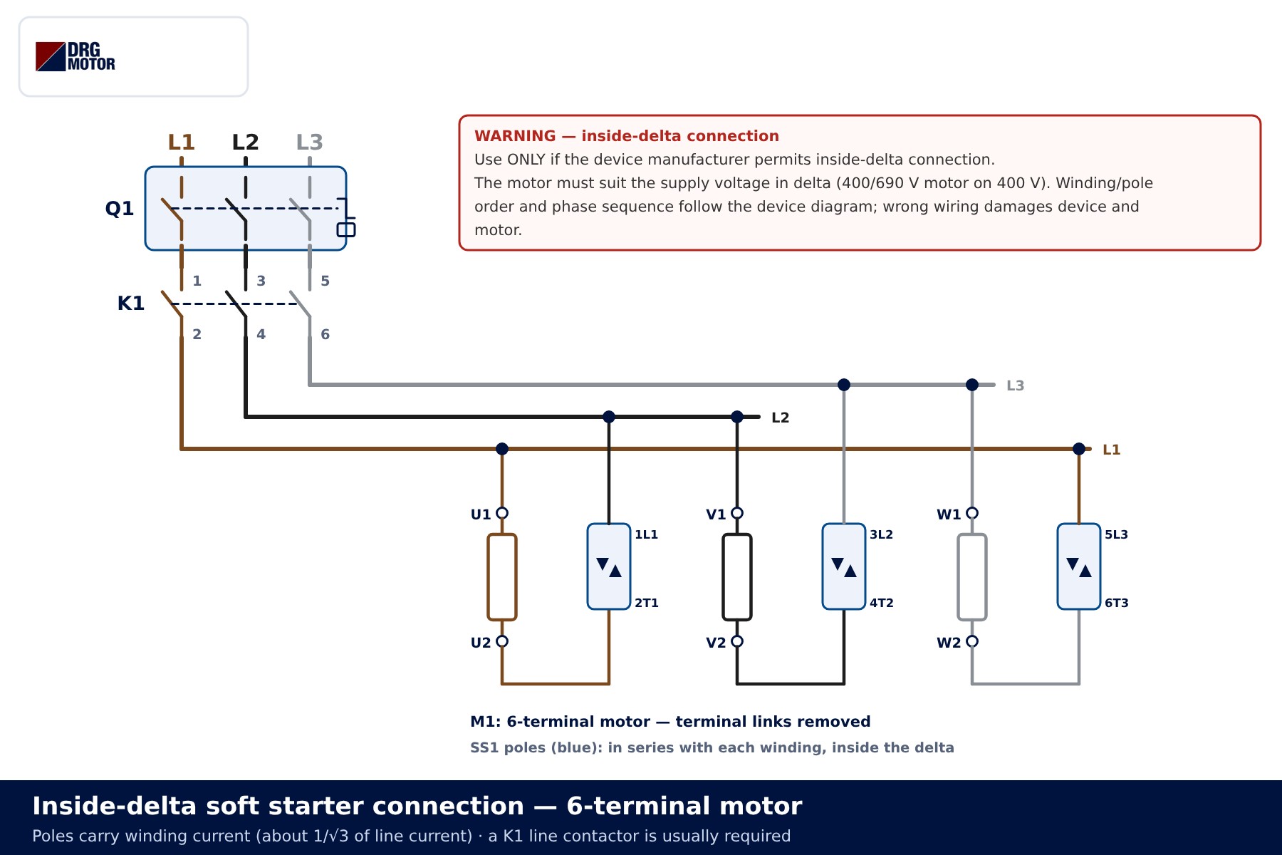
Warning: use this connection only if the device manufacturer explicitly allows it and the device is set to inside-delta mode. The motor must be rated for the supply voltage in delta (a 400/690 V motor on 400 V). If the winding-to-pole pairing and phase sequence do not follow the device diagram, both device and motor can be damaged. A line contactor (K1) is usually required with this connection.
Common wiring mistakes
| Symptom | Likely cause |
|---|---|
| Q1 trips when KB closes | Phase order mixed between KB input and output terminals |
| Device reports overcurrent or “no current” after bypass | KB connected to terminals outside the current sensing |
| Motor fails to accelerate during the ramp, device heats up | Initial voltage or current limit too low for the load; motor undersized for the duty |
| “Phase loss” fault at start | Loose connection or fuse in one phase; check for phase loss |
| Voltage measured on terminals of a stopped motor | No K1; thyristors do not isolate |
| Device trips at start, capacitors on the output | Power-factor correction fitted on the device output |
If overload protection is not built into the device, a separate overload relay set to motor current is needed; see thermal overload relay setting for the principle. Our overload, fuse and contactor selection tool, the motor current chart and the motor cable size calculator give first estimates; final selection relies on the device and cable manufacturer’s data.
Selection examples
- 11 kW centrifugal pump: in-line connection, device with internal bypass and a stop ramp. The stop ramp reduces pressure surges in the pipework.
- 22 kW fan: high inertia means a long start. Choose a device rated for the start duration and number of starts per hour; if an external KB is used, prefer the device’s bypass terminals.
- 30–45 kW conveyor: it starts under load, so current limit and initial voltage are set at commissioning to suit it. Inside-delta is considered only if the device permits it and a 400/690 V motor is used.
If you are still choosing the starting method, the details are in Star-delta vs soft starter.
Send a photo of your current motor nameplate and we will find the suitable DRG model together.Send on WhatsApp
DRG motors for soft starter operation
DRG Motor is a manufacturer, supplier and seller of electric motors. The 400/690 V Δ/Y wound models below run in delta on a 400 V in-line connection; the same winding also suits inside-delta wiring when the device allows it. Soft starters, contactors and relays are not sold by DRG; please contact your panel component supplier or the device manufacturer. All options are listed under three-phase asynchronous electric motors and in the online store.
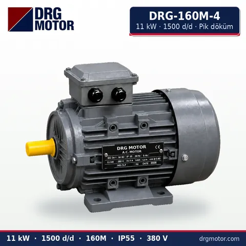
11 kW Three-Phase Motor 1500 rpm – DRG-160M-4 Cast Iron
- 11 kW · 1500 rpm (4 poles)
- Cast iron frame · IEC 160M
- Mounting: B3 · B5 · B14 · B35
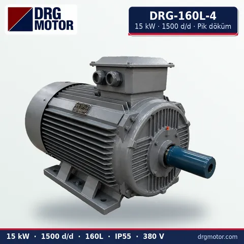
15 kW Three-Phase Motor 1500 rpm – DRG-160L-4 Cast Iron
- 15 kW · 1500 rpm (4 poles)
- Cast iron frame · IEC 160L
- Mounting: B3 · B5 · B14 · B35
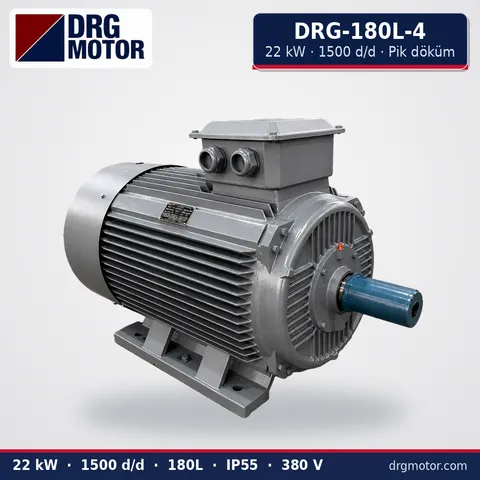
22 kW Three-Phase Motor 1500 rpm – DRG-180L-4 Cast Iron
- 22 kW · 1500 rpm (4 poles)
- Cast iron frame · IEC 180L
- Mounting: B3 · B5 · B14 · B35
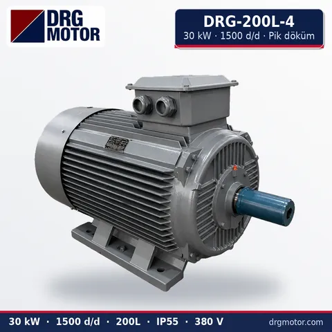
30 kW Three-Phase Motor 1500 rpm – DRG-200L-4 Cast Iron
- 30 kW · 1500 rpm (4 poles)
- Cast iron frame · IEC 200L
- Mounting: B3 · B5 · B14 · B35
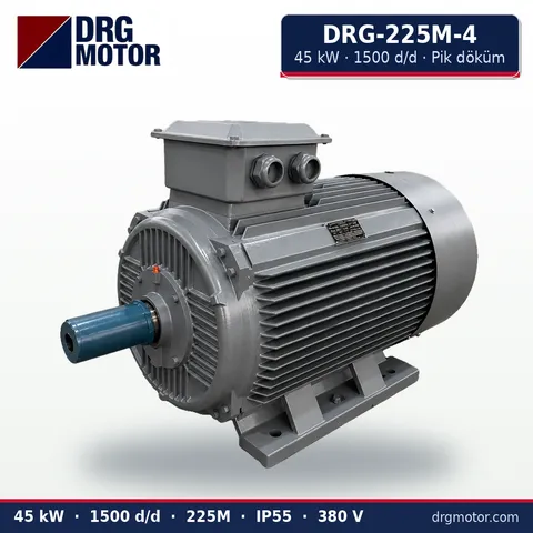
45 kW Three-Phase Motor 1500 rpm – DRG-225M-4 Cast Iron
- 45 kW · 1500 rpm (4 poles)
- Cast iron frame · IEC 225M
- Mounting: B3 · B5 · B14 · B35
Click to see current prices for these motors and order nowSEE PRICES →
Frequently asked questions
Is a K1 line contactor mandatory with a soft starter?
Not in every application, but thyristors do not provide galvanic isolation, so K1 is used when the motor must be disconnected from the supply at stop and on fault. Most devices require a line contactor for inside-delta wiring.
Should an external KB be added to a device with internal bypass?
Usually not. An additional bypass is fitted only if the device manufacturer provides for it, and on the terminals it specifies.
Can a timer relay close KB instead of the top-of-ramp relay?
Not recommended. A timer does not know whether the motor has actually reached full voltage; with a heavier load KB could close while the ramp is still running. Use the device’s own top-of-ramp output.
Does a soft starter control motor speed?
No. It only varies voltage during start and stop; in operation the motor runs at its speed for the supply frequency. Speed control requires a drive.
📄 Download Wiring Diagram PDF A4 printable PDF of the diagrams and tables (no sign-up)





