 English
 Le français
 Türkçe





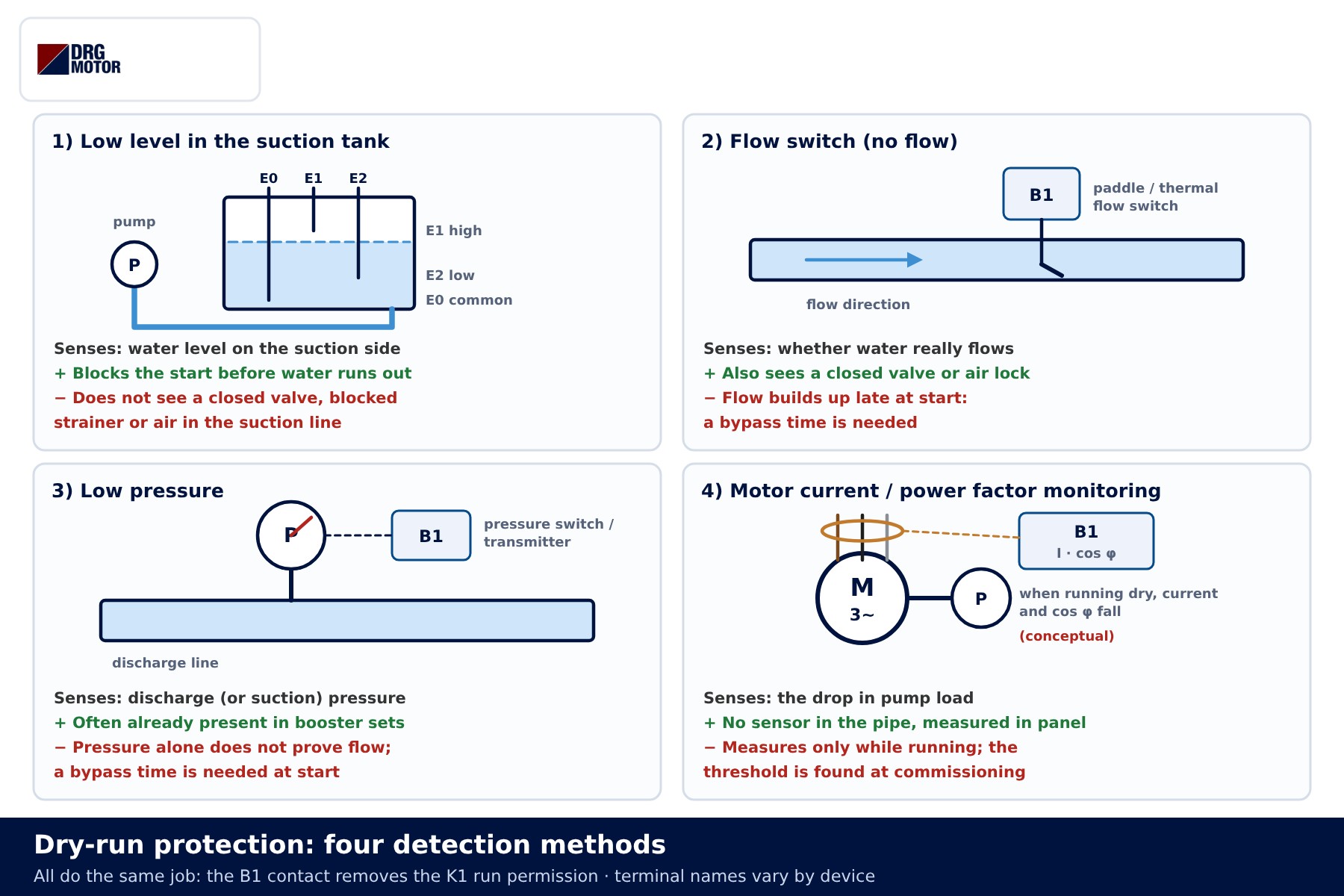
Dry-run protection means a contact that senses the pump has no water and opens the path to the K1 contactor coil of the pump motor. Detection can use a low-level electrode in the suction tank, a flow switch, low pressure, or a relay that monitors motor current or power factor. In a sound control circuit the protection contact is wired in series with the K1 coil, a short bypass time is allowed at start-up, and the fault is latched so the pump can only restart after a manual reset.
Safety notice: This content is for technical information only. Wiring, measurement and commissioning must be carried out by qualified electrical personnel, following lock-out and verification of de-energised state, and in line with the motor and device manufacturer's documentation.
Below we compare the four detection methods, then show the power circuit, the series run permission, the bypass time, the fault latch and the H2 fault lamp in diagrams. All diagrams are examples; terminal names vary by device and the device’s own wiring diagram prevails.
What does running dry do to the pump and motor?
In a centrifugal pump the gland packing or mechanical seal, the bearing bushes and the impeller are lubricated and cooled by the water passing through. When water stops, that cooling disappears: seal faces heat up within a short time, plastic parts may deform and trapped air causes cavitation and vibration. On the motor side the picture is misleading: a dry pump draws less power, so the overload relay sees nothing. A motor protection breaker or overload relay is therefore not dry-run protection; a separate detection is needed.
Many booster and well pump motor failures start this way: the seal leaks and water reaches the motor bearing or terminal box. Typical causes are covered in why a booster pump motor burns out.
Four detection methods: what does each one see?
All methods end up doing the same job: a contact opens on “no water” and removes the K1 run permission. They differ in what they actually sense and in which fault they miss.
| Method | What it senses | Strength | Watch out for |
|---|---|---|---|
| 1. Low level in suction tank (electrode or float) | Water level in the tank | Stops before the water runs out; blocks the start | Misses a closed valve, blocked strainer or air leak in the suction |
| 2. Flow switch | Whether water really flows | Sees every no-flow condition | Flow builds up late at start; a bypass time is needed |
| 3. Low pressure | Discharge or suction pressure | Often already fitted on booster sets | Pressure alone does not prove flow; bypass needed at start |
| 4. Current / power factor monitoring (conceptual) | The drop in pump load | No sensor in the pipework; measured in the panel | Works only while the motor runs; threshold set at commissioning |
In practice the most robust solution is often a combination: where there is a suction tank, low-level detection blocks the start, while flow or load monitoring catches a no-flow condition that appears during operation. Float and level relay wiring details are outside the scope of this article; here they are simply a B1 sensor giving a “water / no water” contact.
Power circuit and components
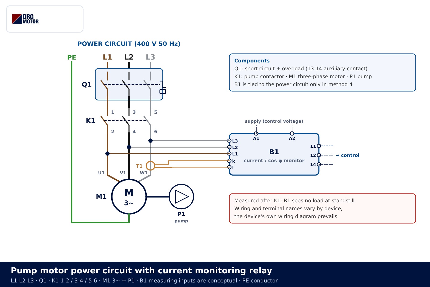
The power circuit is a plain direct-on-line starter: Q1 motor protection breaker, K1 contactor and M1 three-phase motor. If a current or power factor monitoring relay is used, it measures after K1 on the motor side, so it sees no load while the motor is stopped and does not raise a false fault. How the relay inputs are connected (direct voltage, current transformer, etc.) depends on the device.
| Component | Terminals | Function |
|---|---|---|
| Q1 motor protection breaker | 1…6 main, 13-14 auxiliary | Short-circuit and overload protection; its auxiliary cuts the control |
| K1 pump contactor | A1-A2, 1…6, 13-14, 53-54 | Connects the motor; 13-14 holds, 53-54 starts the bypass timer |
| B1 dry-run sensor | 11-12 / 11-14 (changeover) | With water present, 11-14 closed and 11-12 open |
| K3 timer (on-delay) | A1-A2, 17-18 | Holds the protection off for the bypass time t_b after start |
| K2 fault relay | A1-A2, 13-14, 21-22, 43-44 | Latches the fault, cuts K1, lights H2 |
| S0 / start button / S2 | 11-12 NC / 13-14 NO / 11-12 NC | Stop, start and fault reset |
| H2 fault lamp | X1-X2 | Shows the dry-run fault |
Q1 and the contactor are sized from the motor nameplate current; the overload, fuse and contactor selection tool and the motor current chart give a starting point. The difference between Q1 and a separate overload relay is explained in this article.
Click to see current electric motor prices and order nowSEE PRICES →
Why is the protection contact wired in series with the K1 coil?
The dry-run contact is a run permission. It sits in the path to the K1 coil, in line with the stop button and the Q1 auxiliary contact. With water present it is closed and stays out of the way; when water is lost it opens and interrupts the coil current. The most common omission is wiring the contact only to a warning lamp or a separate signal line without touching K1: the lamp lights, but the pump keeps running dry.
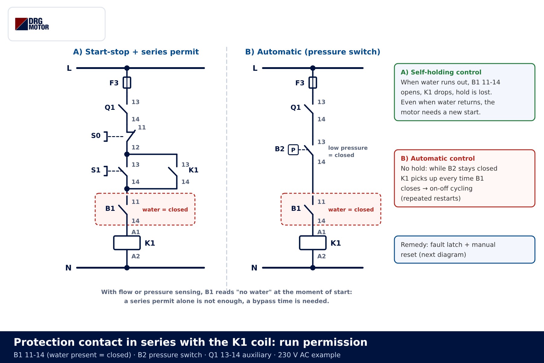
In the self-holding start-stop control on the left, the series permit works well on its own: when water is lost K1 drops, the hold is released, and even if water returns the motor only starts with a new start command. The automatic pressure-switch control on the right has no hold. As long as pressure stays low, B2 is closed, and every time B1 reports water K1 picks up again. A little water collects in the suction, the pump starts, empties it, stops, and the cycle can repeat for hours. For both pump and motor this is worse than a single dry run. Frequent starting is also discussed in if a booster pump motor starts too often.
The second problem comes with flow and pressure sensing: while the pump is stopped there is no flow and pressure is low. B1 reports “no water” at the moment of start and K1 can never pick up. For these two reasons a bypass time and a fault latch are added to the series permit.
📄 Download Wiring Diagram PDF A4 printable PDF of the diagrams and tables (no sign-up)
Bypass time at start-up, fault latch and manual reset
The control circuit below has four rungs. Rung one is the familiar start-stop chain, with one difference: the K2 21-22 NC contact sits just before the K1 coil. In rung two, K1 53-54 starts the on-delay timer K3. Rung three is the K2 fault relay: the S2 reset button (NC), K3 17-18 and B1 11-12 are in series, and K2’s own 13-14 contact is wired across K3 and B1 as a hold. In rung four, H2 lights through K2 43-44.
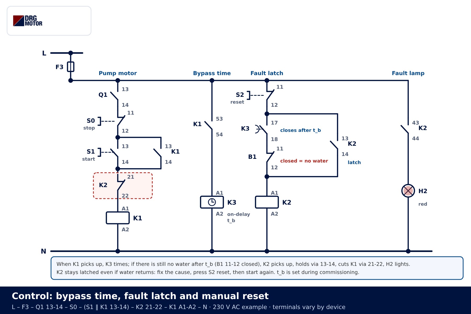
The bypass time t_b is the time allowed for the pump to fill its suction and build up flow and pressure. While it runs, K3 17-18 is open, so K2 cannot pick up whatever B1 reports. Once it has elapsed, if B1 still reports no water, K2 picks up. The value of t_b depends on the pump type, suction lift and installation and is found by observation during commissioning. Setting it longer than needed simply means running the pump dry for that long at every start.
The fault latch stops the pump from restarting itself over and over. Once K2 picks up it holds via 13-14; even if water returns and B1 11-12 opens, K2 does not drop. K1 can only be started again after someone has checked the cause and pressed S2. One caveat: on a power cut K2 also drops and the fault memory is lost. If the fault must be remembered after an outage, a relay or controller with retentive memory is used, chosen according to the site risk assessment.
Step-by-step operation and shutdown sequence
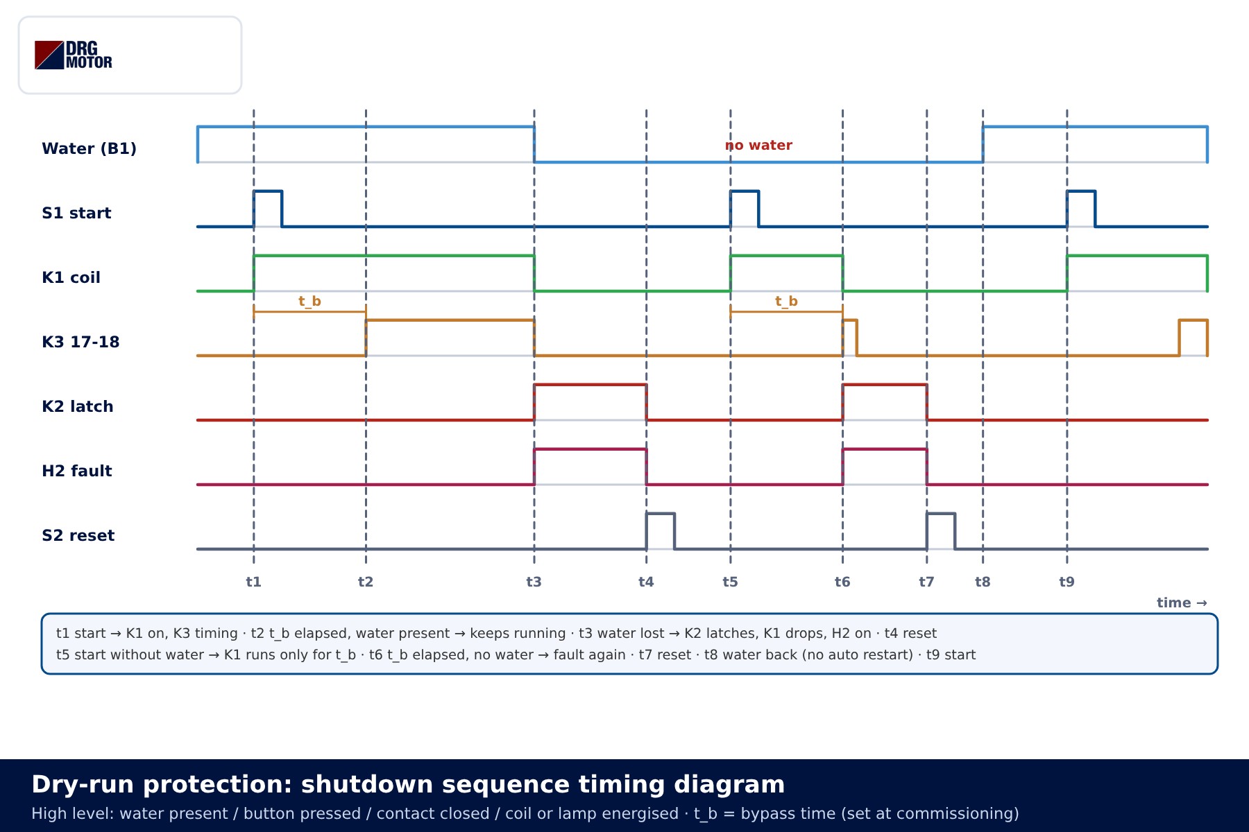
- Start (t1): the start button is pressed, K1 picks up and holds via 13-14. K1 53-54 closes and K3 starts timing.
- Bypass time elapsed (t2): K3 17-18 closes. With water present B1 11-12 is open, K2 stays off and the pump runs normally.
- Water lost while running (t3): B1 11-12 closes and K2 picks up at once (K3 is already closed). K2 21-22 opens, K1 drops, the motor stops and H2 lights.
- Water returns: K2 stays latched and the pump does not start. This is intended.
- Reset (t4): S2 is pressed, K2 drops and H2 goes out. The motor stays stopped and waits for a new start.
- Start without water (t5–t6): K1 picks up and the pump runs only for t_b. If there is still no water when it ends, K2 picks up again and cuts K1.
- Back to normal (t7–t9): reset, water returns, start, and operation resumes.
State table
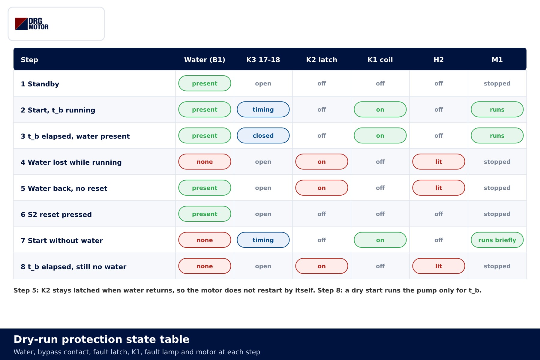
The table is meant for comparing measured contact states during fault-finding. Note row five in particular: the motor being stopped with H2 lit although water is present is not a fault but the expected result of the latch.
| State | K2 fault relay | K1 / motor | H2 |
|---|---|---|---|
| Standby, water present | off | off / stopped | off |
| Start, bypass time running | off | on / running | off |
| Water lost while running | latched | off / stopped | lit |
| Water back, no reset yet | latched | off / stopped | lit |
| Reset pressed | off | off / waiting for start | off |
| Start given without water | latched after t_b | runs for t_b, then stops | lit |
Common wiring mistakes
| Symptom | Likely cause |
|---|---|
| H2 lights but the pump keeps running dry | The protection contact only feeds the lamp; no series contact in the K1 chain |
| The pump never starts and drops out as soon as start is pressed | No bypass time with flow/pressure sensing, or B1 wired on the wrong contact (11-12 instead of 11-14) |
| The pump restarts by itself when water returns and cycles on and off | No fault latch; K2 13-14 missing or the reset button is NO |
| Pressing reset starts the pump | Reset wired into the K1 rung instead of start; reset must only drop K2 |
| The current monitoring relay trips while the motor is stopped | Measurement taken before K1, or the relay start delay not used |
| Wiring correct but occasional trips at start | t_b shorter than the pump filling time; possible air leak in the suction line |
If the overload relay on the motor trips often, the cause is usually overload or phase imbalance rather than dry running; see phase loss for a checklist. Another application of self-holding, timer and interlock logic is described in the star-delta control circuit.
Selection examples
- 2.2 kW booster pump drawing from an open tank, 3000 rpm: a low-level electrode in the tank blocks the start; in addition, a fault latch with bypass time is added to the pressure-switch circuit. A 230/400 V motor is connected in star on a 400 V supply.
- 4 kW transfer pump with a long suction line: if the tank cannot be monitored, a flow switch or current/power factor monitoring is preferred; t_b is set by watching how long the suction takes to fill. A 400/690 V motor is connected in delta on a 400 V supply.
- 7.5 kW irrigation pump on a well: where a sensor is hard to fit, load monitoring is a practical choice; the threshold is set at commissioning between the values measured at normal flow and with the valve closed.
- Cable: the cross-section depends on route length and installation method; the motor cable size calculator gives a starting value.
📄 Download Wiring Diagram PDF A4 printable PDF of the diagrams and tables (no sign-up)
Send a photo of your current motor nameplate and we will find the suitable DRG model together.Send on WhatsApp
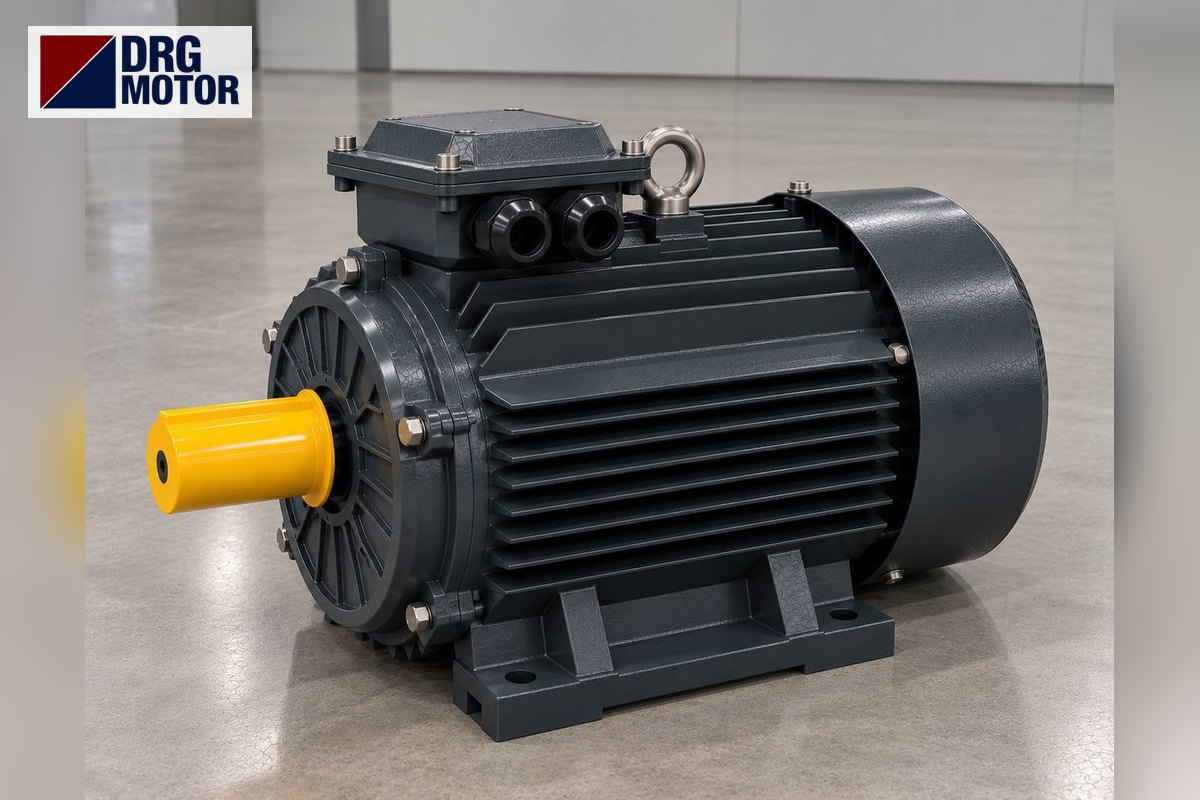
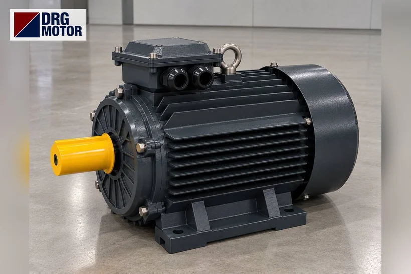
DRG three-phase motors for pump applications
DRG Motor is an electric motor manufacturer, supplier and seller. The 3000 rpm class three-phase IEC motors below fall within the power range commonly used on booster and transfer pumps. Dry-run relays, flow switches, pressure switches, floats, contactors and timers are not sold by DRG; please contact your panel component supplier or the device manufacturer for those. Other ratings and speeds are listed on the three-phase asynchronous electric motors page and in the online store.
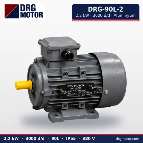
2.2 kW Three-Phase Motor 3000 rpm – DRG-90L-2 Aluminium
- 2.2 kW · 3000 rpm (2 poles)
- Aluminium frame · IEC 90L
- Mounting: B3 · B5 · B14 · B35
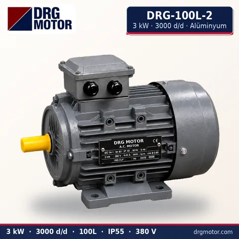
3 kW Three-Phase Motor 3000 rpm – DRG-100L-2 Aluminium
- 3 kW · 3000 rpm (2 poles)
- Aluminium frame · IEC 100L
- Mounting: B3 · B5 · B14 · B35
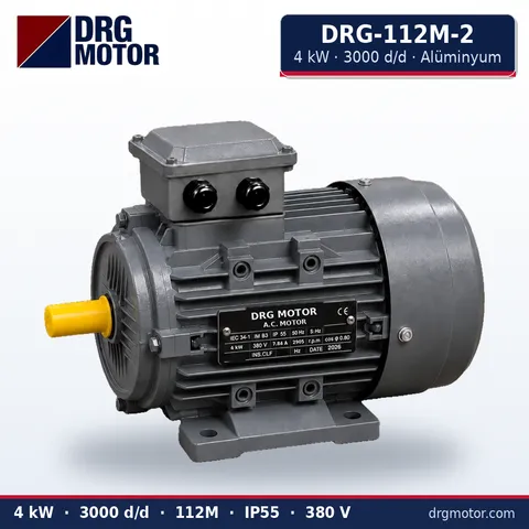
4 kW Three-Phase Motor 3000 rpm – DRG-112M-2 Aluminium
- 4 kW · 3000 rpm (2 poles)
- Aluminium frame · IEC 112M
- Mounting: B3 · B5 · B14 · B35
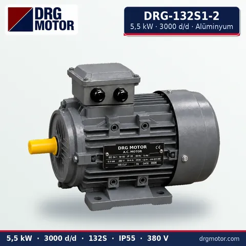
5.5 kW Three-Phase Motor 3000 rpm – DRG-132S1-2 Aluminium
- 5.5 kW · 3000 rpm (2 poles)
- Aluminium frame · IEC 132S
- Mounting: B3 · B5 · B14 · B35
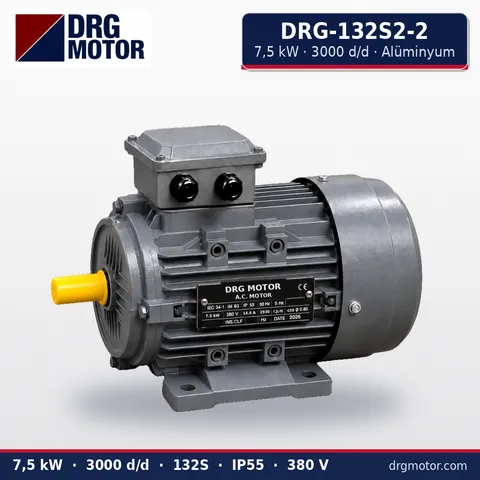
7.5 kW Three-Phase Motor 3000 rpm – DRG-132S2-2 Aluminium
- 7.5 kW · 3000 rpm (2 poles)
- Aluminium frame · IEC 132S
- Mounting: B3 · B5 · B14 · B35
Click to see current prices for these motors and order nowSEE PRICES →
Frequently asked questions
Does an overload relay protect against dry running?
No. A dry pump draws less power and motor current falls, so the overload relay does not trip. Dry running needs its own detection and a contact wired in series with the K1 coil.
How long should the bypass time be?
There is no fixed value. The time the pump needs to fill its suction and build up flow and pressure is observed at commissioning; t_b is set long enough to cover it, but short enough not to allow needless dry running.
Why should the fault not reset automatically?
Automatic reset lets the pump start, empty the suction and stop every time a little water collects. This on-off cycling wears the seal and the motor more than a single dry run. A manual reset makes sure someone looks at the cause.
Does a current monitoring relay work on every pump?
It works well on pumps whose load drops clearly when running dry. On lightly loaded motors the current difference may be small, which is why some relays monitor power factor or power instead. The threshold must always be set on the actual pump during commissioning.
Is the fault memory lost on a power cut?
The K2 relay in this diagram drops when the supply is lost, so yes. If the fault must survive an outage, a relay or controller with retentive memory is chosen.





