 English
 Le français
 Türkçe





When a motor is commissioned on a drive for the first time, the order is: de-energised checks, reading the nameplate and verifying the star/delta links, an insulation test with the drive disconnected; then power-up, entering the nameplate values as parameters, auto-tuning in the way the manufacturer permits, a direction check at low speed, ramps and limits, a trial under load and the record. Parameter values always come from the motor nameplate, never from estimates.
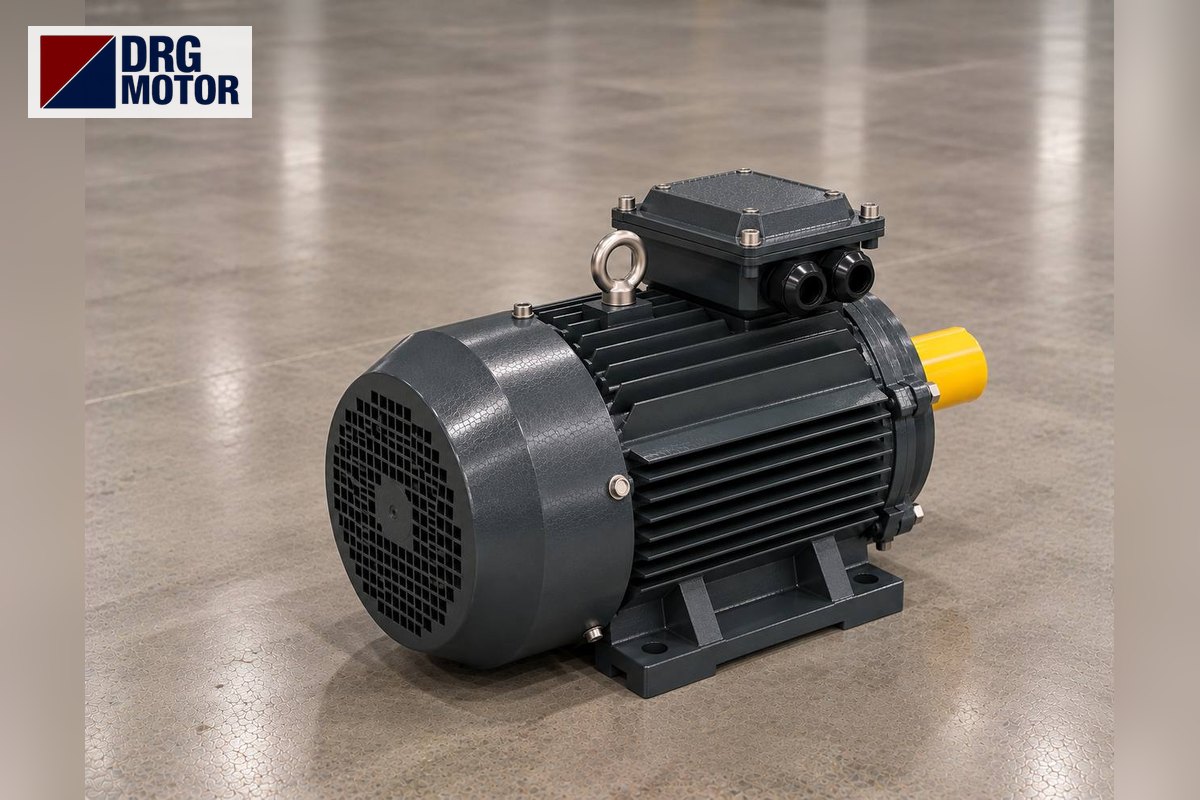
Safety notice: This content is for technical information only. Wiring, measurement and commissioning must be carried out by qualified electrical personnel, following lock-out and verification of de-energised state, and in line with the motor and device manufacturer's documentation.
The diagrams below are examples for a three-phase input drive and a three-phase induction motor on a 400 V 50 Hz supply. Terminal and parameter names vary by device; the device's own wiring diagram and documentation prevail. For the terminology, see frequency converter vs inverter.
Commissioning sequence: an 11-step flow
The flow chart splits the job into four colour zones: work done de-energised (1–4), power on but motor stopped (5–7), motor running (8–10) and documentation (11). If a step fails, go back: stop, isolate, fix the cause and repeat that step. Skipping ahead – testing insulation with the drive still connected, or starting auto-tuning before the nameplate data is in – puts both the device and the motor at risk.
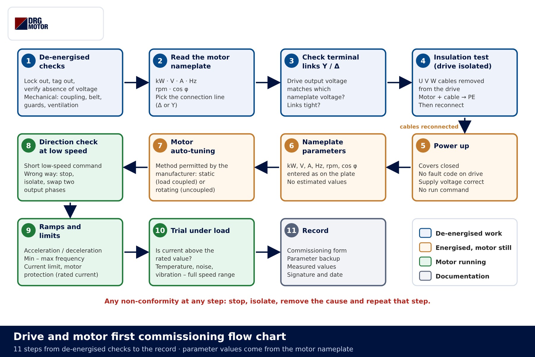
In the first step the supply is switched off, locked and tagged, and the absence of voltage is confirmed with a tester. Then the mechanics: coupling alignment and bolts, belt tension, shaft key, guards, fan cover and a clear air inlet. A motor that has spent a long time in storage needs extra bearing and winding checks, described in motor storage and commissioning.
Nameplate and terminal links: star or delta?
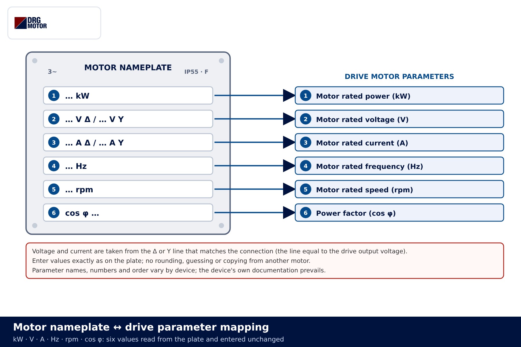
Six values are read from the plate: power (kW), voltage (V), current (A), frequency (Hz), speed (rpm) and power factor (cos φ). On a three-phase plate the voltage and current usually appear twice: one line for delta (Δ), one for star (Y). The terminal links decide which line applies.
The rule is simple: if the drive's phase-to-phase output voltage equals the Δ value on the plate, connect delta; if it equals the Y value, connect star. A 230/400 V Δ/Y motor runs in star on a 400 V output drive and in delta on a 230 V output (single-phase input) drive. A 400/690 V Δ/Y motor runs in delta on a 400 V output drive. For 230 V drives see motor selection for a 220 V inverter; link layouts are shown in the star-delta connection diagram.
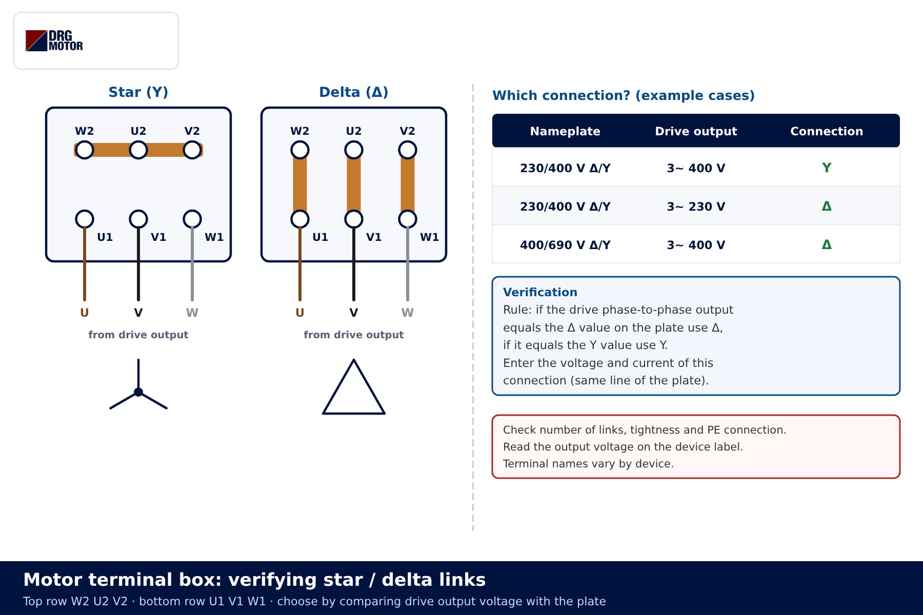
In the terminal box, check the number and direction of the links, nut tightness and the PE connection. A motor on a drive does not use a star-delta contactor set: the drive ramp handles the start and the motor keeps one fixed connection.
Insulation test with the drive disconnected
Never insulation-test the drive. The tester voltage can damage the output semiconductors and filter components. The U, V and W cores of the motor cable are removed from the drive terminals, temporarily linked together if required, and the test is made between motor + cable and PE.
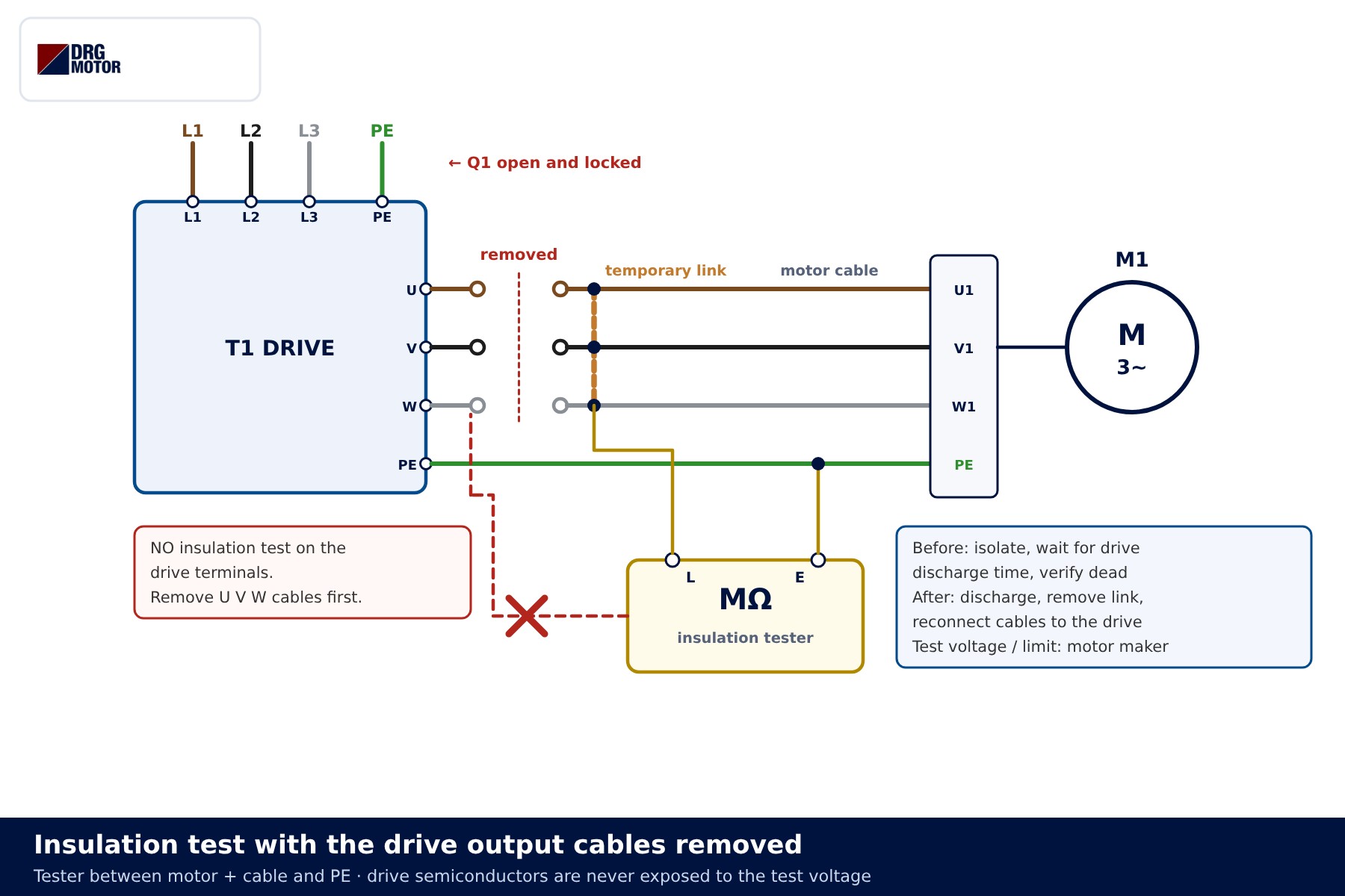
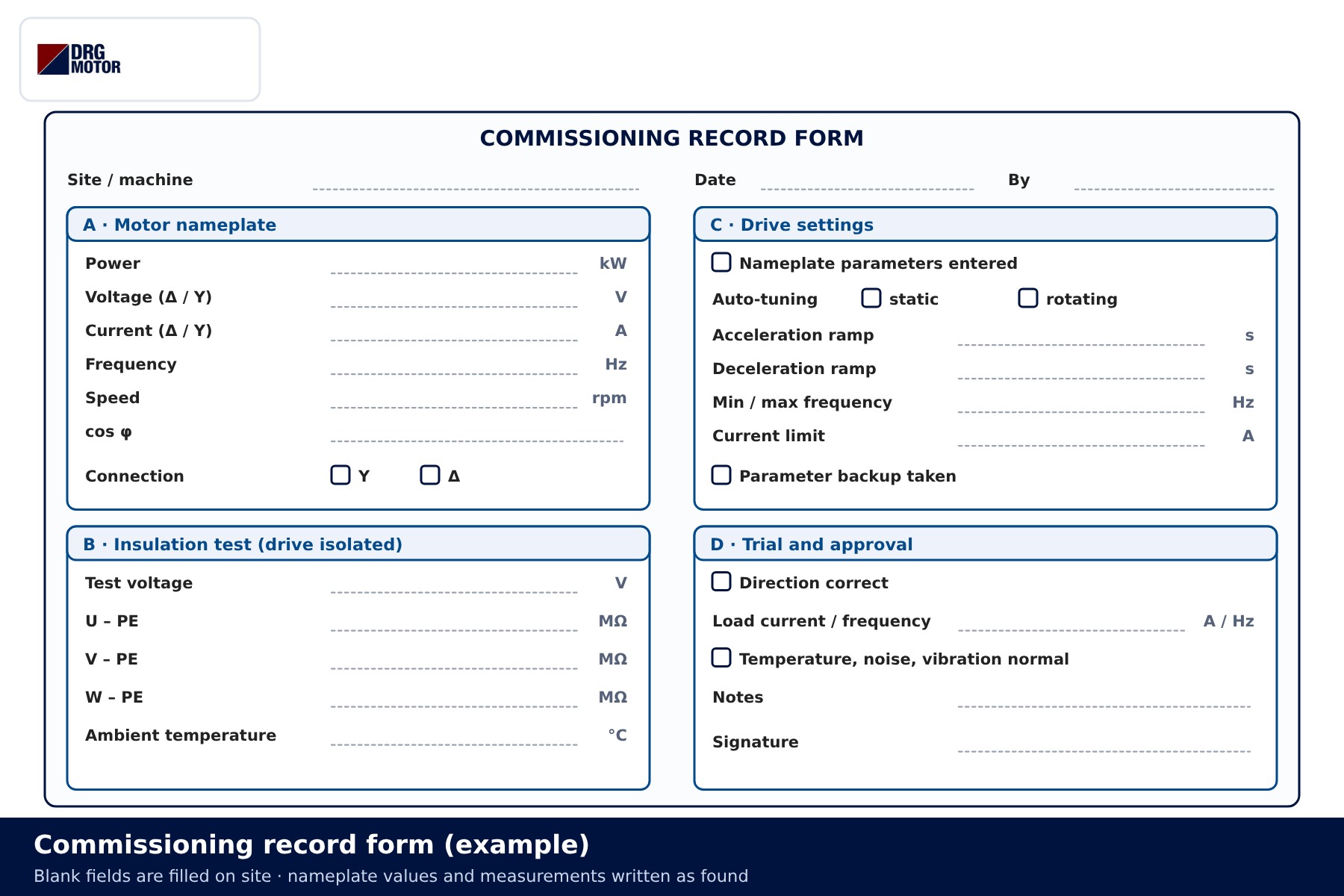
Before removing the cables, isolate the drive and wait for the discharge time printed on the device; the DC link capacitors stay charged for a while after switch-off. After the test, discharge the cable and winding, remove the temporary link and reconnect the cores to the drive in the correct order. Test voltage and acceptance value follow the motor manufacturer's documentation; the method is covered in motor insulation resistance (megger) test. Write the reading and ambient temperature on the record form – it is your reference for later maintenance.
📄 Download Wiring Diagram PDF A4 printable PDF of the diagrams and tables (no sign-up)
Click to see current electric motor prices and order nowSEE PRICES →
Power and control wiring, then power-up
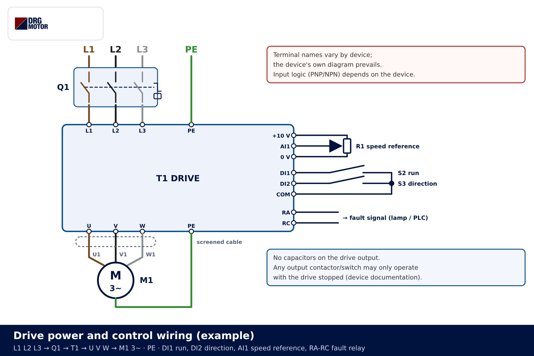
In the example, the supply reaches the drive L1 L2 L3 input through the Q1 motor protection breaker; the motor is connected to U V W with a screened cable and PE goes to both drive and motor. On the control side DI1 is run and DI2 direction; potentiometer R1 on +10 V, AI1 and 0 V gives the speed reference; the RA-RC fault relay drives a lamp or the upper control system.
| Item | Terminals | Function |
|---|---|---|
| Q1 motor protection breaker / fuses | L1 L2 L3 | Protects the drive input; type and rating per device documentation |
| T1 drive | L1 L2 L3 / U V W / PE | Converts the supply into a variable-frequency motor voltage |
| M1 three-phase motor | U1 V1 W1 + PE | Connected Y or Δ according to its plate |
| S2 run switch | DI1 – COM | Gives the run command |
| S3 direction switch | DI2 – COM | Selects direction (if used) |
| R1 potentiometer | +10 V / AI1 / 0 V | Analogue speed reference |
| Fault relay | RA – RC | Signals a drive fault |
No power factor capacitors on the drive output. If there is an output contactor or isolator, it may only switch with the drive stopped. Cable size depends on run length and installation method; the motor cable size calculator gives a starting value. Long motor cables, voltage rise times and winding insulation are discussed in VFD motor insulation and forced cooling.
Before power-up, close the covers and keep the run command off. Once energised, confirm the input voltage on the display or with a meter and check that no fault code is shown.
Nameplate parameters and auto-tuning
The drive's motor parameters map one-to-one to the plate: rated power, rated voltage, rated current, rated frequency, rated speed and cos φ. Voltage and current are taken from the line (Δ or Y) that matches the connection. Do not round values or copy them from another motor. If the plate is unreadable, confirm the motor type and rating with the manufacturer; the motor current chart gives typical values but does not replace the plate.
Auto-tuning lets the drive measure values such as stator resistance and inductance to build its motor model; speed and torque accuracy in vector control depend on it. Two methods are common:
- Static tuning: the shaft does not turn and the measurement is made at standstill. Chosen when the load cannot be uncoupled and the device manufacturer allows it.
- Rotating tuning: the motor turns on its own for a short time. The load should be uncoupled or light; secure the shaft end, key and surroundings.
The method, the loaded/unloaded condition and the state of any mechanical brake during tuning are as the device manufacturer specifies. Do not move on until tuning completes without a fault.
Direction check at low speed, ramps and limits
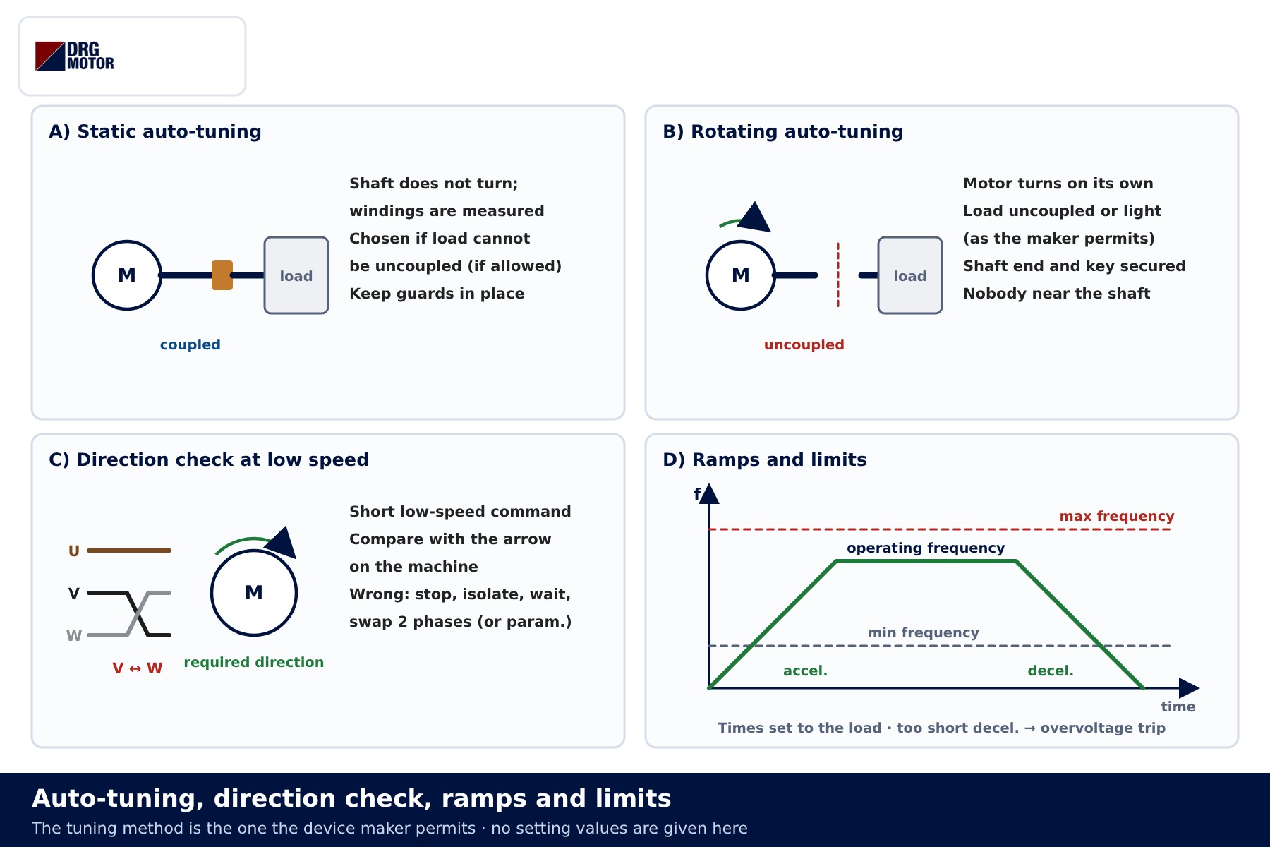
Check the direction with a low speed reference and a short run command, comparing with the arrow on the machine. If it is wrong, stop the motor, isolate, wait for the discharge time and swap two phases at the drive output; many devices can also reverse by parameter. Swapping phases on the supply side does not change motor direction. More in why an electric motor runs backwards.
Next set the acceleration and deceleration ramps, minimum and maximum frequency, current limit and motor overload protection. These depend on the load, the machine and the device documentation, so we give no figures here. Motor protection current starts from the rated current on the plate. If deceleration is too short for the load inertia, the drive may trip on overvoltage: lengthen the ramp or consider a braking resistor. Self-ventilated motors cool less at low speed, so applications that run slowly for long periods need cooling considered separately.
Trial under load, checklist and record
Under load, run the motor across its full operating speed range. Compare the motor current shown by the drive with the rated current; watch temperature, noise, vibration and the bearing area. If the current is higher than the load justifies, check the mechanics (binding, alignment, belt) and the parameters first.
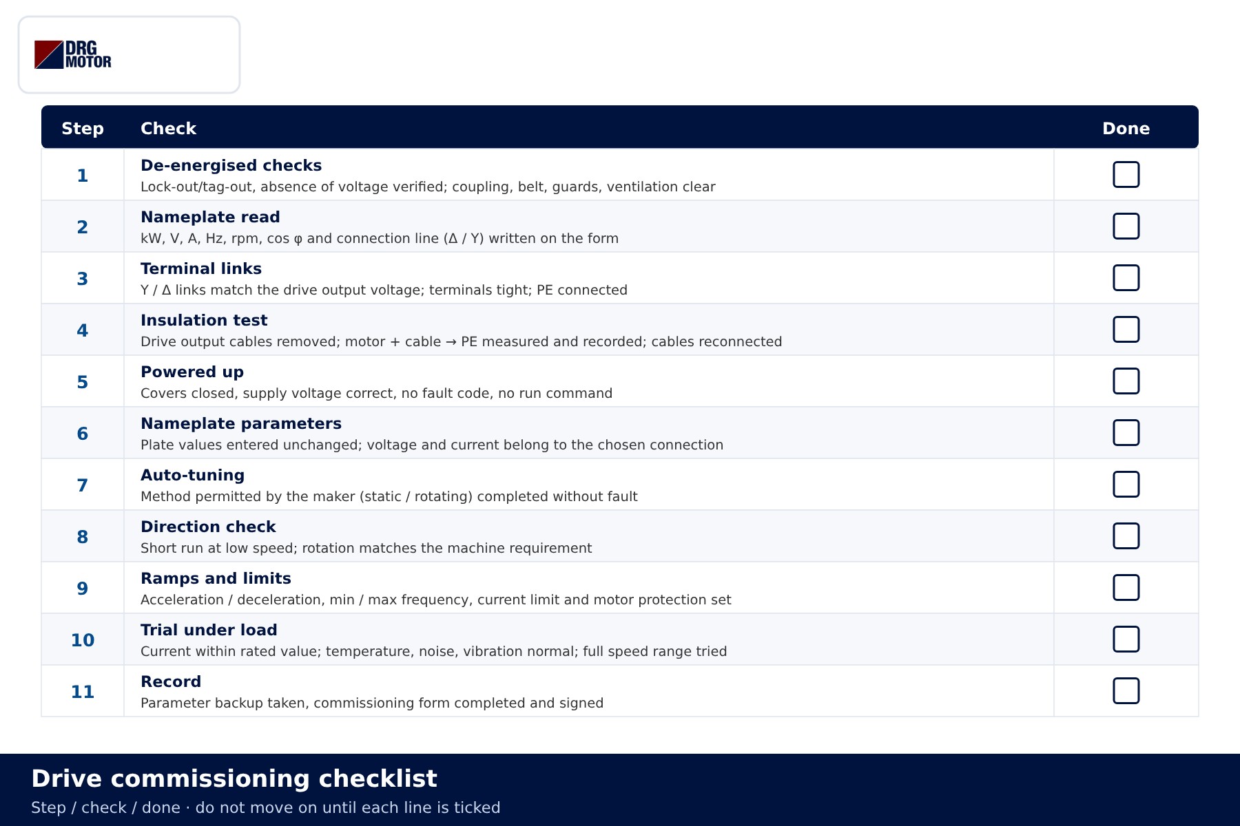
| Step | Check | What to record |
|---|---|---|
| 1–3 | De-energised checks, plate, links | Nameplate values, Y/Δ choice |
| 4 | Insulation (drive disconnected) | Test voltage, U-V-W / PE readings, temperature |
| 5–7 | Power-up, parameters, tuning | Values entered, tuning method and result |
| 8–9 | Direction, ramps, limits | Direction correct, ramp and limit settings |
| 10–11 | Load trial, record | Load current and frequency, parameter backup, signature |
The last step is the record. Back up the parameter list and complete and sign the commissioning form. When a fault or motor replacement comes up later, this form answers the question "what did it look like on day one?".
Common commissioning mistakes
| Symptom | Likely cause |
|---|---|
| Overcurrent trip on first start | Nameplate data not entered or wrong connection line entered; ramp too short; mechanical binding |
| Motor feels weak, speed drops under load | 400/690 V motor connected in star on a 400 V output drive; no auto-tuning |
| Drive damaged after an insulation test | Test made with the drive terminals still connected |
| Overvoltage trip on deceleration | Deceleration too short for the load inertia, no braking resistor |
| Motor overheats with normal current | Long periods at low speed, fan cover or air path blocked |
| Wrong direction | Output phase sequence; change made on the supply side |
📄 Download Wiring Diagram PDF A4 printable PDF of the diagrams and tables (no sign-up)
Send a photo of your current motor nameplate and we will find the suitable DRG model together.Send on WhatsApp
DRG motors for drive operation
DRG Motor is a manufacturer, supplier and seller of electric motors. The three-phase IEC motors below are in a power range often used with drives; models up to 3 kW are wound 230/400 V, 4 kW and above 400/690 V. Drives and inverters are not sold by DRG; please contact your panel component supplier or the device manufacturer. Other ratings are listed under three-phase asynchronous electric motors and in the online store.
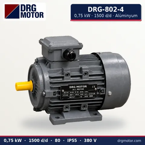
0.75 kW Three-Phase Motor 1500 rpm – DRG-802-4 Aluminium
- 0.75 kW · 1500 rpm (4 poles)
- Aluminium frame · IEC 80
- Mounting: B3 · B5 · B14 · B35
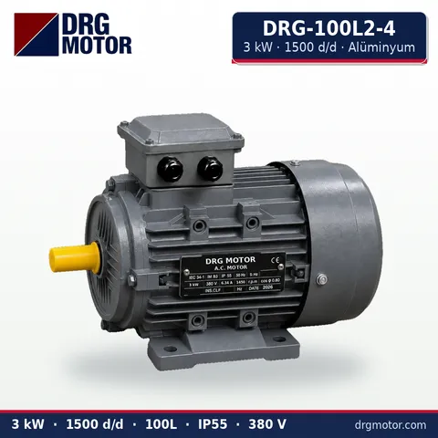
3 kW Three-Phase Motor 1500 rpm – DRG-100L2-4 Aluminium
- 3 kW · 1500 rpm (4 poles)
- Aluminium frame · IEC 100L
- Mounting: B3 · B5 · B14 · B35
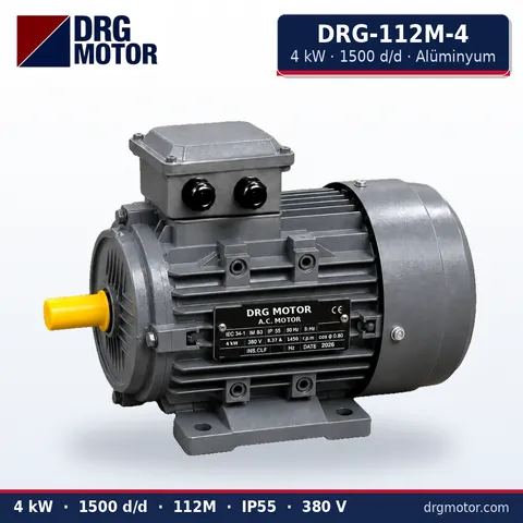
4 kW Three-Phase Motor 1500 rpm – DRG-112M-4 Aluminium
- 4 kW · 1500 rpm (4 poles)
- Aluminium frame · IEC 112M
- Mounting: B3 · B5 · B14 · B35
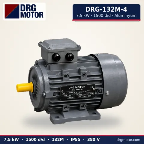
7.5 kW Three-Phase Motor 1500 rpm – DRG-132M-4 Aluminium
- 7.5 kW · 1500 rpm (4 poles)
- Aluminium frame · IEC 132M
- Mounting: B3 · B5 · B14 · B35
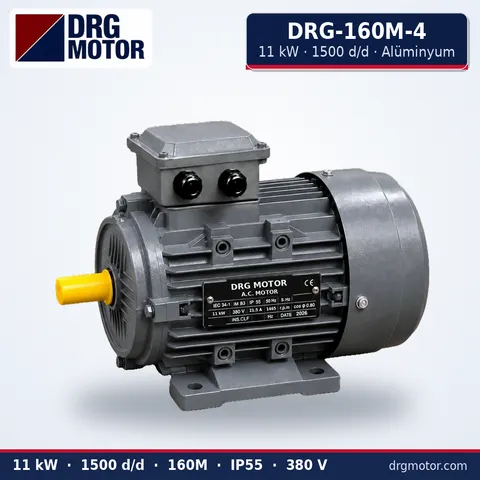
11 kW Three-Phase Motor 1500 rpm – DRG-160M-4 Aluminium
- 11 kW · 1500 rpm (4 poles)
- Aluminium frame · IEC 160M
- Mounting: B3 · B5 · B14 · B35
Click to see current prices for these motors and order nowSEE PRICES →
Frequently asked questions
Can I megger the motor with the drive connected?
No. The test voltage can damage the drive output stage. Remove the motor cable from the drive, test motor + cable to PE, then reconnect.
Should auto-tuning be done loaded or unloaded?
As the device manufacturer permits. Rotating tuning usually requires the load to be uncoupled; if it cannot be and the device supports it, use static tuning.
The plate shows two voltages and two currents – which do I enter?
The line for the connection you made: the voltage equal to the drive output voltage and the current next to it. On a 400 V output, a 230/400 V motor is in star and a 400/690 V motor in delta.
What if the direction is wrong?
Stop, isolate and wait for the discharge time; swap two phases at the drive output or reverse by parameter. Swapping phases on the supply input does not change the direction.
How many seconds should the ramp be?
There is no single figure. It depends on the load inertia, the machine and the device documentation, and is fine-tuned during trials by watching current and fault logs.





