 English
 Le français
 Türkçe





An external start-stop and direction command reaches a drive through the digital inputs (DI) on its control terminal block; no contactor is placed in the U V W motor output, and phases are never swapped to reverse. There are two common methods: in two-wire control the motor runs as long as a maintained contact on DI1 stays closed, with DI2 choosing direction; in three-wire control a start button gives a short pulse, an NC stop button stops the motor when it opens, and the drive latches the command internally. The inputs are usually powered from the drive's internal 24 V supply and its common terminal (COM).
Safety: This content is for technical information only. Wiring, measurement and commissioning must be carried out by qualified electrical personnel, following lock-out and verification of de-energised state, and in line with the motor and device manufacturer's documentation.
For background on what a drive is and how the terms frequency converter and inverter differ, see Frequency Converter vs Inverter. This article deals only with the command side: how buttons, selector switches and PLC contacts are wired to the drive inputs.
Drive control terminals and basic wiring
The power side is simple: L1 L2 L3 pass through a motor protection breaker or the fuses specified by the manufacturer to the drive input, and the drive's U V W output feeds the motor. The control side is a small terminal block. Its digital inputs take the start, stop and direction signals; the speed reference normally arrives on an analogue input (AI1) or through preset speeds.
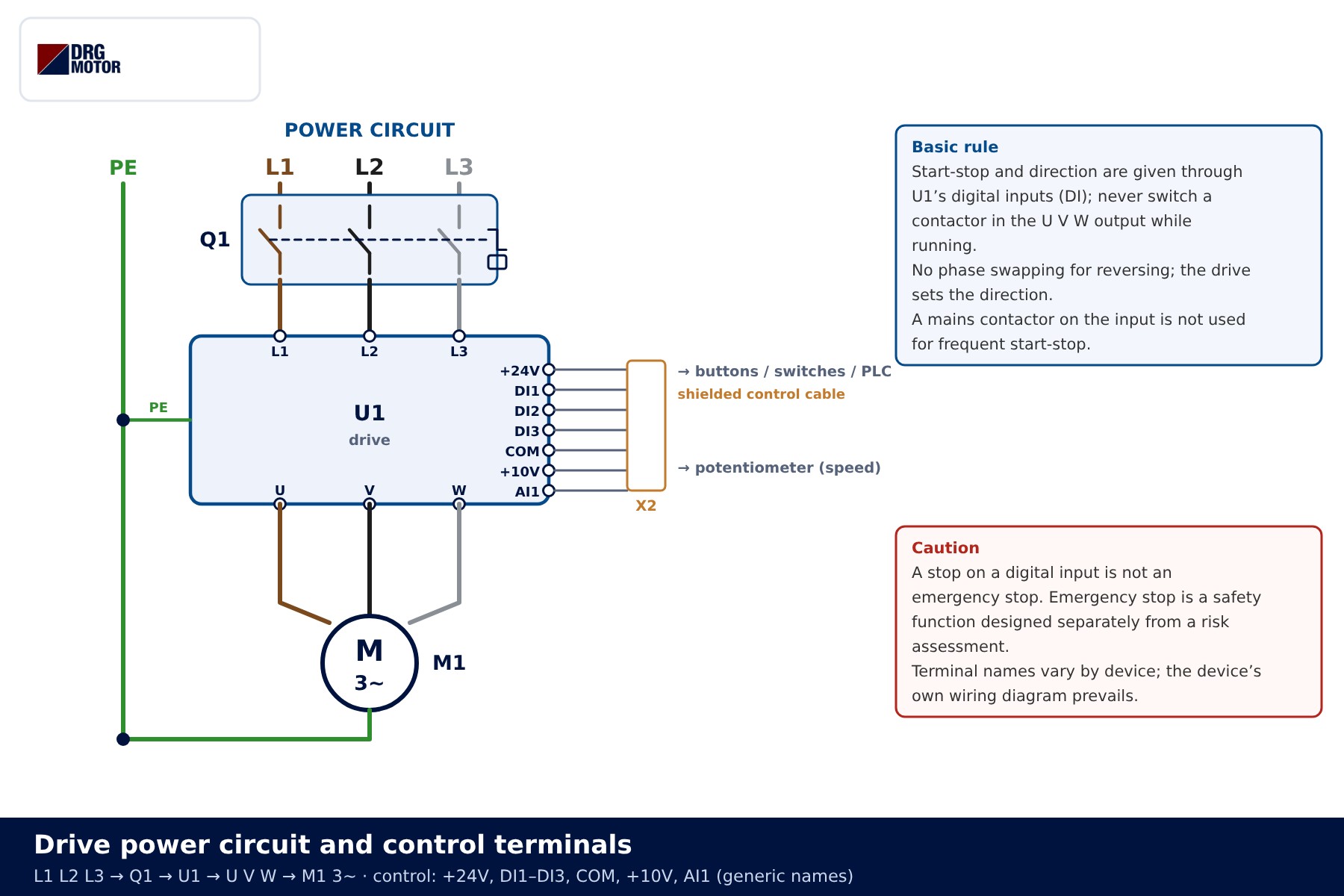
| Component | Generic terminal | Function |
|---|---|---|
| Q1 | L1 L2 L3 | Short-circuit protection of the drive input |
| U1 drive | U V W, PE | Supplies the motor; sets frequency, direction and ramps |
| Internal supply | +24V | Contact supply for the digital inputs |
| Digital inputs | DI1, DI2, DI3 | Run, direction, start/stop (assigned in the settings) |
| Common | COM | Return/common point of the digital inputs (0 V or +24 V side) |
| Speed reference | +10V, AI1 | Potentiometer or PLC analogue signal |
Terminal names vary by device; the device's own wiring diagram prevails. Some drives label the inputs "FWD/REV", others "X1, X2…"; the logic is the same. Two basic rules apply: never open or close a contactor in the U V W line of a running drive, and do not use a mains contactor on the drive input for frequent start-stop. Direction is changed by a drive command, not by rewiring; the link between phase sequence and rotation is covered in why an electric motor runs backwards.
Emergency stop note: a stop button on a digital input is not an emergency stop. That input is an ordinary command processed by software. Emergency stop and safe stopping are designed as a separate safety function based on the machine's risk assessment.
📄 Download Wiring Diagram PDF A4 printable PDF of the diagrams and tables (no sign-up)
Two-wire control: maintained contact = run, DI2 = direction
In two-wire control DI1 is wired to a maintained contact such as a switch, thermostat, level contact or PLC relay. While the contact stays closed the drive runs; as soon as it opens, the drive stops with the selected stop mode (ramp or coast). A second contact on DI2 sets direction: open for forward, closed for reverse.
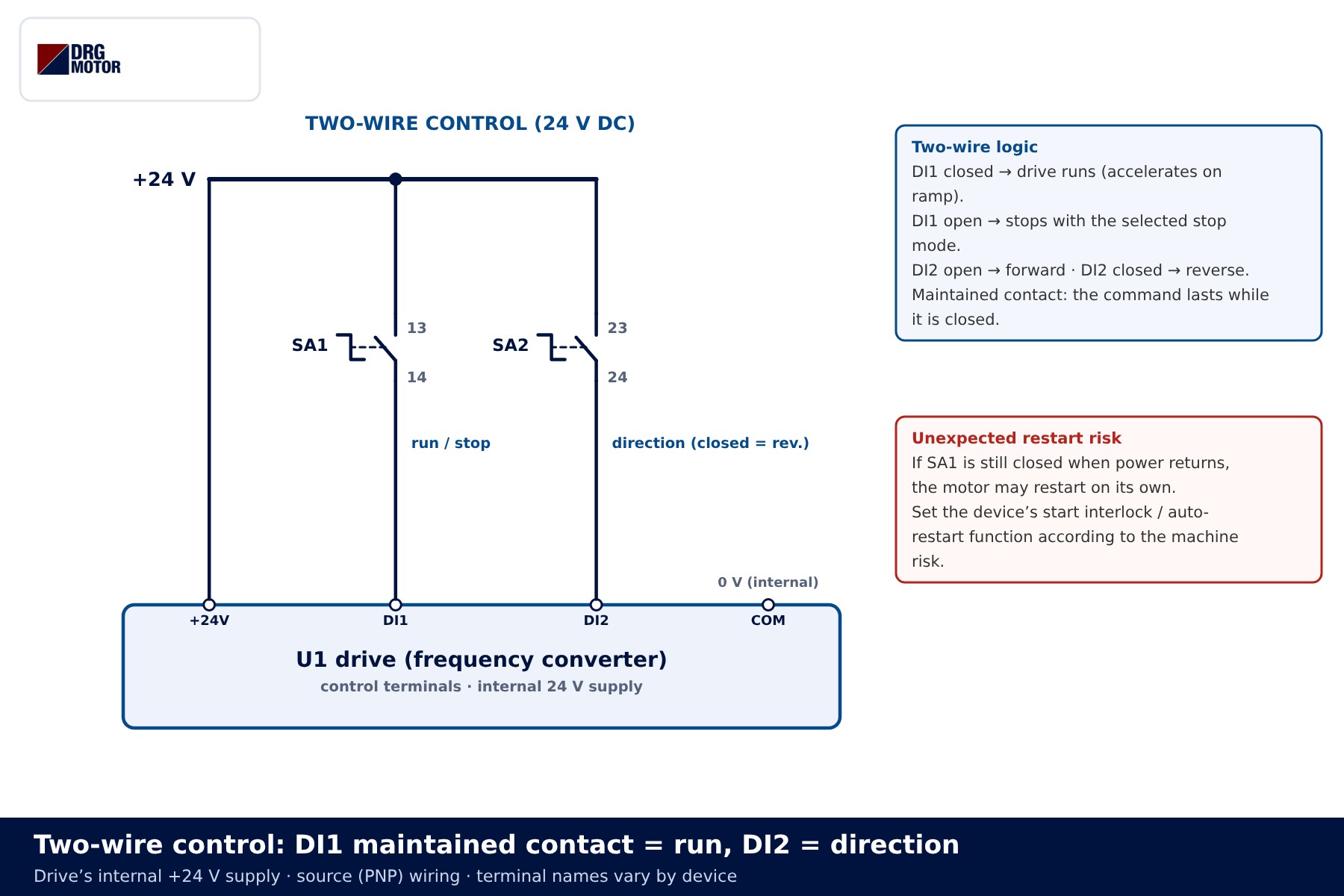
- SA1 closes: DI1 sees +24 V and the drive accelerates on its ramp.
- SA2 closes: DI2 becomes active; the drive decelerates, passes through zero and runs up to the same reference speed in reverse.
- SA1 opens: the run command disappears and the motor stops.
Unexpected restart risk: in a two-wire circuit the contact itself is the command. If SA1 is still closed when power returns after an outage, the drive sees a run command as soon as it powers up and the motor may restart on its own. On pumps and fans that may be the wanted behaviour; on a conveyor, mixer or any machine where people intervene, it is dangerous. Most drives offer a "start interlock" or "auto-restart" option; which one to use depends on the machine risk.
Click to see current electric motor prices and order nowSEE PRICES →
Three-wire control: start pulse, NC stop and direction
Three-wire control is the drive's internal version of a contactor self-holding circuit. The start button (S2, NO) sends a short pulse to DI1; the stop button (S0, NC) sits on DI2 and is normally closed. The drive latches the start pulse and keeps running until the stop input opens. Direction is selected by a maintained switch (SA2) on DI3. The contactor equivalent of this latch is shown in the star-delta control circuit article.
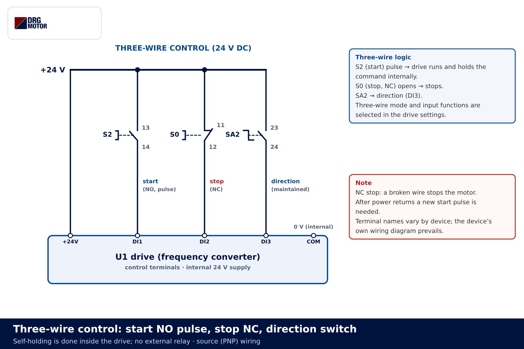
- Start pressed: DI1 receives a pulse; with S0 closed the drive runs.
- Start released: DI1 opens but the drive keeps running (internal latch).
- Stop pressed: DI2 opens, the drive stops and clears the command.
- Power lost and restored: the command has been cleared; the motor waits for a new start pulse.
Choosing an NC stop button is deliberate: if a wire breaks or a terminal works loose, DI2 opens and the motor stops. Three-wire mode and the input functions are selected in the drive menu; the same terminals mean something else in two-wire mode.
Forward/reverse with two inputs: DI1 forward, DI2 reverse
In the third common layout each input is both a run and a direction command: DI1 closed runs forward, DI2 closed runs in reverse, and with both open the motor stops. It is built with an I-0-II selector switch or two PLC relay outputs.
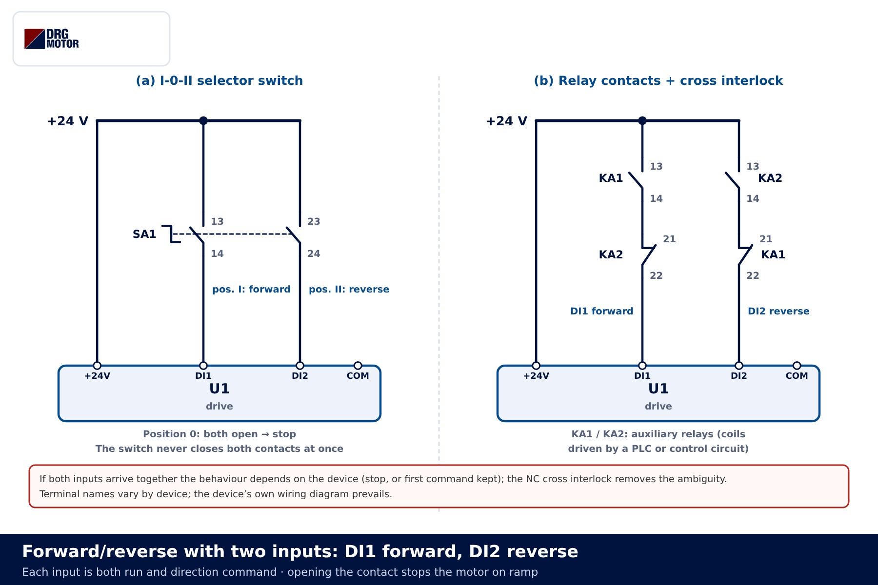
A selector switch cannot close both contacts at once. With relays or a PLC both inputs can arrive together, and the drive's reaction depends on the device: some stop, others keep the first command. To remove that ambiguity, each relay's NC contact is placed in series with the opposite input, as in the diagram (cross interlock). Fast reversals force the drive to brake the motor and load inertia; if overvoltage trips appear, look at dynamic braking and braking resistors.
Internal 24 V, COM and PNP/NPN (source/sink)
Inside each digital input there is an optocoupler LED with a series resistor. The input counts as "active" when current flows through that LED. The direction of that current defines the wiring type:
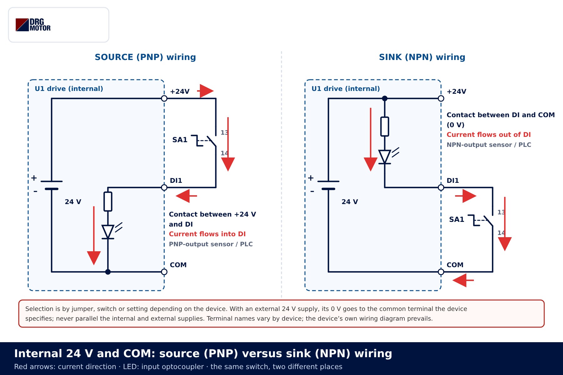
| Wiring | Contact position | Current direction | Suitable signal source |
|---|---|---|---|
| Source (PNP) | Between +24V and DI | Flows into DI, returns via COM (0 V) | PNP-output sensor, sourcing PLC output |
| Sink (NPN) | Between DI and COM (0 V) | Flows out of DI | NPN-output sensor, sinking PLC output |
The mode is chosen with a jumper, a small switch or a parameter, depending on the device. Dry contacts such as buttons and relay contacts work in both modes; only their position changes. With sensors or PLC outputs, the output type must match the drive's input mode. If an external 24 V supply is used, its 0 V goes to the common terminal the device specifies; never connect the internal and external supplies in parallel.
State table and timing diagram
The drawing below puts the three wiring types in one table. Red rows are the cases that need care.
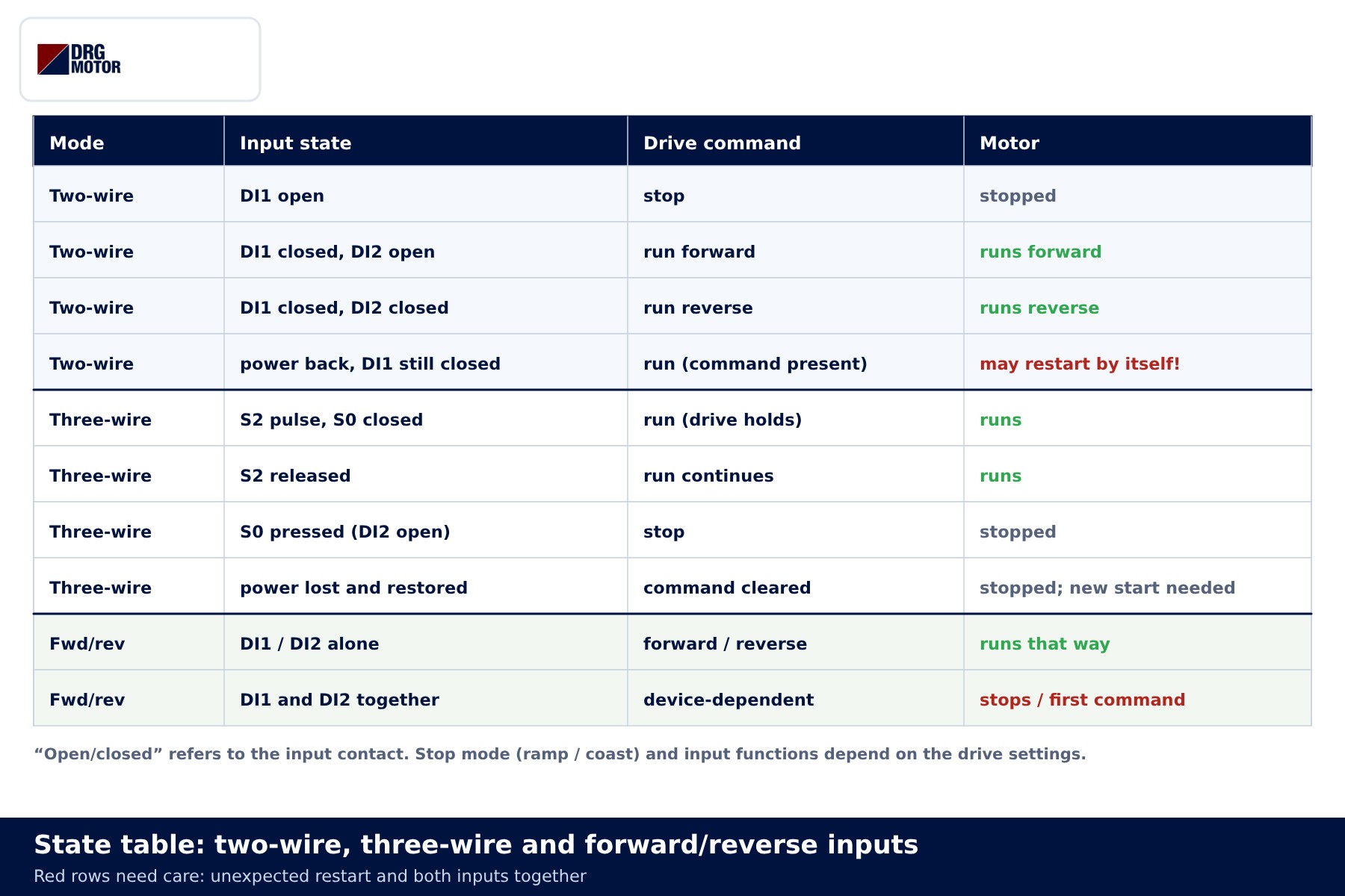
| Situation | Two-wire | Three-wire | Forward/reverse inputs |
|---|---|---|---|
| Command given | Runs while DI1 stays closed | A start pulse is enough | Runs while DI1 or DI2 stays closed |
| Command contact released | Motor stops | Motor keeps running | Motor stops |
| Change of direction | DI2 changes; motor passes through zero | DI3 changes | The other input is closed |
| Power returns | May restart by itself if the contact is closed | New start needed | May restart by itself if the contact is closed |
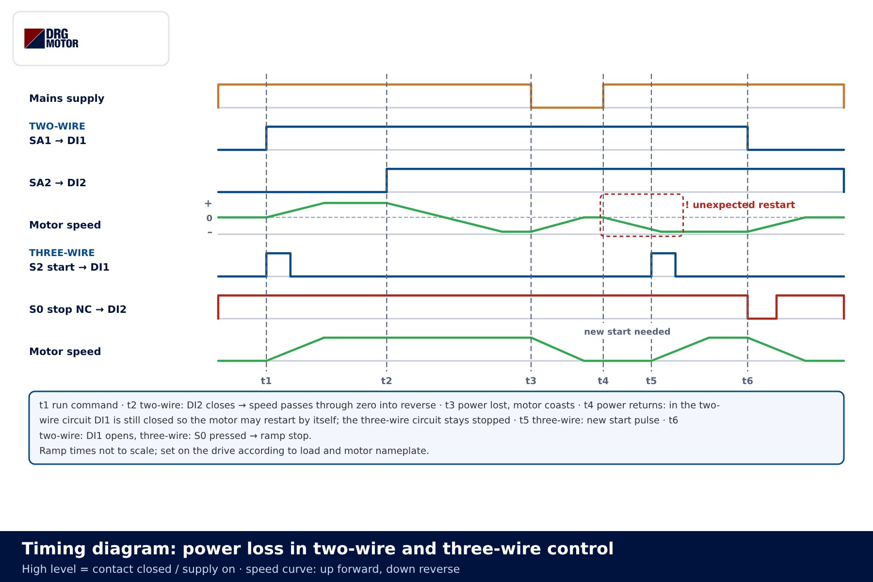
In the timing diagram power is lost at t3 and returns at t4. In the two-wire circuit SA1 is still closed, so the motor accelerates on its own; in the three-wire circuit it stays stopped until the new start pulse at t5. Ramp times are not to scale; they are set on the drive according to load inertia and the motor nameplate.
Common wiring mistakes
| Symptom | Likely cause |
|---|---|
| Nothing happens when the button is pressed | Input mode (PNP/NPN) does not match the wiring, or the command source is set to "keypad" instead of "terminals" |
| Motor stops when start is released | Drive is in two-wire mode; three-wire mode not selected |
| Motor never runs, new stop button fitted | An NO contact was wired instead of the NC stop; DI2 always looks open |
| Motor restarts by itself after an outage | Two-wire control with auto-restart enabled |
| Inputs trigger at random | Unshielded control cable in the same tray as the motor cable; shield not earthed |
| Drive trips on overvoltage when reversing | Deceleration ramp too short for the load; braking needed |
| Inputs dead after adding an external 24 V | 0 V not connected to COM, or supply paralleled with the internal one |
Use shielded cable for control wiring and route it away from the motor cable. For a first estimate of motor cable size use the motor cable size calculator, and for rated current the motor current chart; the final choice follows the device and cable manufacturer's data.
Selection examples
- Liquid transfer pump, 3 kW: two-wire control from a level contact makes sense; the pump runs when the contact closes. Restarting after an outage is the intended behaviour here, but that decision still comes from a risk assessment.
- Belt conveyor, 5.5 kW: with an operator nearby, three-wire control with an NC stop is preferred; the belt will not move by itself when power returns. Emergency stop is designed separately.
- Reversing washing drum, 4 kW: two PLC relays on DI1 forward / DI2 reverse with a cross interlock. Frequent reversing raises motor temperature; for long periods at low speed, consider insulation and forced cooling for VFD motors.
If the drive has a single-phase 230 V input, the motor terminal connection must suit it; see motor selection for a 220 V inverter. The electric motor calculator helps with power and current.
Send a photo of your current motor nameplate and we will find the suitable DRG model together.Send on WhatsApp
DRG motors for use with a drive
DRG Motor is a manufacturer, supplier and seller of electric motors. The three-phase asynchronous motors below can be run from a drive; models up to 3 kW are wound for 230/400 V, 4 kW and above for 400/690 V. Drives, push buttons, relays and PLCs are not sold by DRG; please contact your panel equipment supplier or the device manufacturer for those. All power and speed options are listed on the three-phase asynchronous electric motors page and in the online store.
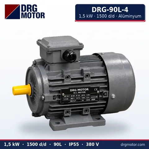
1.5 kW Three-Phase Motor 1500 rpm – DRG-90L-4 Aluminium
- 1.5 kW · 1500 rpm (4 poles)
- Aluminium frame · IEC 90L
- Mounting: B3 · B5 · B14 · B35
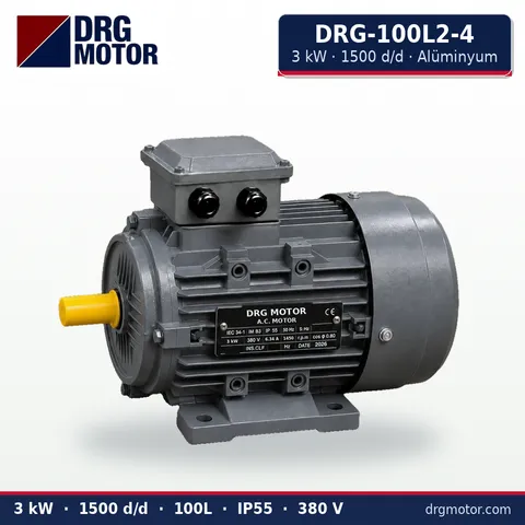
3 kW Three-Phase Motor 1500 rpm – DRG-100L2-4 Aluminium
- 3 kW · 1500 rpm (4 poles)
- Aluminium frame · IEC 100L
- Mounting: B3 · B5 · B14 · B35
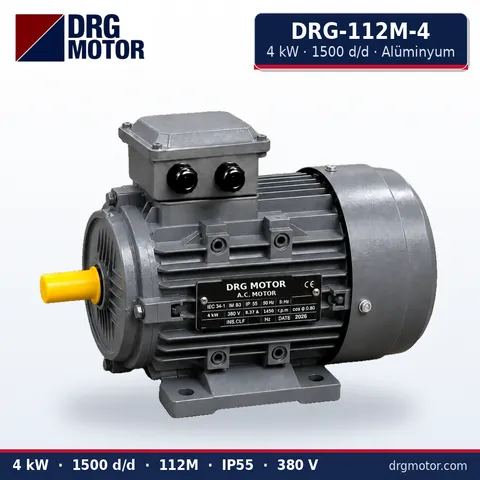
4 kW Three-Phase Motor 1500 rpm – DRG-112M-4 Aluminium
- 4 kW · 1500 rpm (4 poles)
- Aluminium frame · IEC 112M
- Mounting: B3 · B5 · B14 · B35
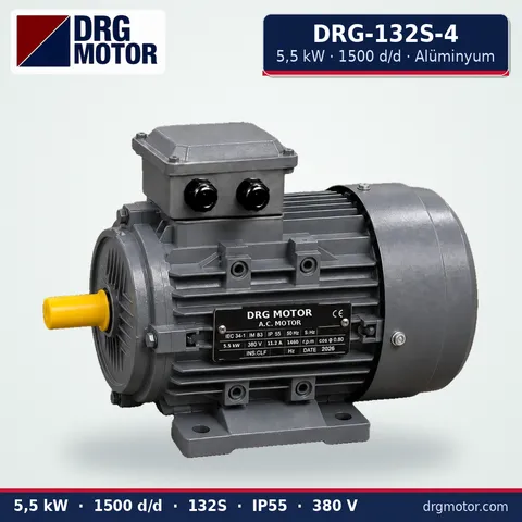
5.5 kW Three-Phase Motor 1500 rpm – DRG-132S-4 Aluminium
- 5.5 kW · 1500 rpm (4 poles)
- Aluminium frame · IEC 132S
- Mounting: B3 · B5 · B14 · B35
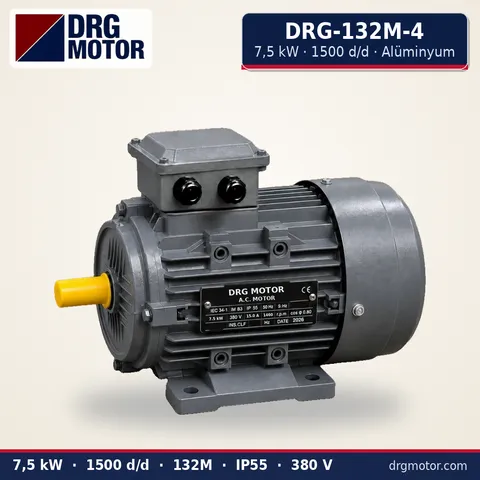
7.5 kW Three-Phase Motor 1500 rpm – DRG-132M-4 Aluminium
- 7.5 kW · 1500 rpm (4 poles)
- Aluminium frame · IEC 132M
- Mounting: B3 · B5 · B14 · B35
Click to see current prices for these motors and order nowSEE PRICES →
Frequently asked questions
Should I use two-wire or three-wire control?
Use two-wire when the command comes from a switch, thermostat or a maintained PLC output; use three-wire when an operator works with push buttons and the motor must not restart by itself after an outage.
Do I swap two motor phases to change direction?
No. On a drive, direction is changed by an input command or a setting. The motor leads may be rearranged once at commissioning so that the "forward" command gives the wanted rotation.
Can sensors be powered from the drive's internal 24 V?
The internal supply has limited current capacity, which varies by device. It is usually enough for a few buttons and a small sensor; for more load use an external 24 V supply with its 0 V tied to the common terminal.
Can the stop button on a digital input replace an emergency stop?
No. A digital input is an ordinary command handled by software. Emergency stop is designed from a risk assessment with a separate safety circuit or the drive's safety inputs.
📄 Download Wiring Diagram PDF A4 printable PDF of the diagrams and tables (no sign-up)





