English
 Le français
 Türkçe




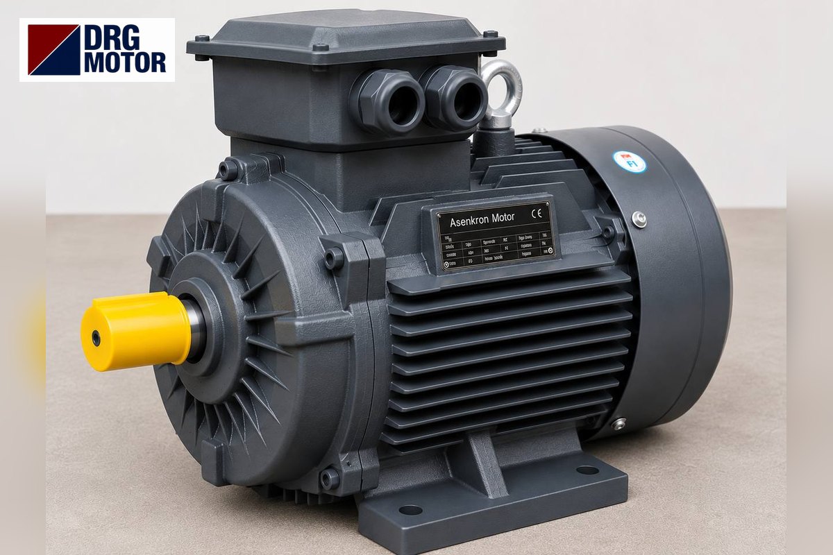

When choosing a new motor in place of a 5.5 kW WAT electric motor, the real decision point is mounting: is the motor fixed to the machine by its feet, by its flange or by both, and is the existing motor a standard or compact frame? This article explains the frame options on the WAT side, the mounting codes, and the order in which to compare mounting dimensions with DRG MOTOR models.
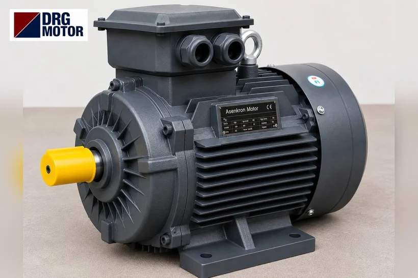
5.5 kW may come in three frame sizes
The WAT IM tr 24.0 catalogue does not give a single frame for 5.5 kW. At 2 poles, the standard Q3H132S2C and HS-type Q3HS132S2C have frame 132 and a 38×80 mm shaft; the compact Q3H112M2D has frame 112 and the super-compact Q3H100L2E frame 100, both with a 28×60 mm shaft. At 4 poles, the standard Q3H132S4B has frame 132 and a 38×80 mm shaft; the compact Q3H112M4E has frame 112 and a 28×60 mm shaft. The cast-iron Q3HSG132S2C and Q3HG132S4B are also frame 132.
So even if two WAT nameplates say 5.5 kW and the same speed class, the shaft height can be 100, 112 or 132 mm. A motor whose shaft centre sits 20–32 mm lower or higher cannot be placed on the same feet position; on coupled drives the difference can only be bridged with a spacer plate or a new base. The first thing to check is the frame number in the type code.
Mounting code: foot, flange or both
In the WAT type code, the field before the frame number shows the mounting:
- Empty field: foot-mounted (B3)
- FA: B5 flange (large flange with through holes)
- PA: B35 (feet + B5 flange)
- FB / FC: B14 flange types; PB / PC: feet + B14
For a foot-mounted motor the deciding dimensions are H, A, B and the foot-hole diameter. For a flanged motor, the flange outer diameter (P), spigot diameter (N), bolt circle (M) and hole diameter (S) are decisive; shaft height becomes secondary because the motor is carried by the flange. For B35, both groups of dimensions must match.
Mounting dimensions of DRG MOTOR models
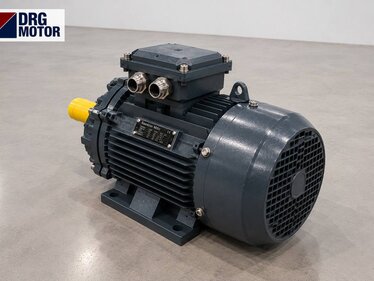
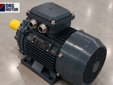
DRG Motor is an electric motor manufacturer, supplier and seller. Mounting dimensions of DRG options that can be assessed for 5.5 kW (mm):
| Model | Frame, H, shaft | Feet: A × B / K | B5 flange: P / N / M / S |
|---|---|---|---|
| DRG-132S1-2 (2-pole, 2930 rpm) | 132S, 132, 38×80 | 216 × 140 / 4–Φ12 | 300 / 230 / 265 / 14.5 |
| DRG-132S-4 (4-pole, 1460 rpm) | 132S, 132, 38×80 | 216 × 140 / 4–Φ12 | 300 / 230 / 265 / 14.5 |
| DRG-112M-4K (compact, 4-pole, 1460 rpm) | 112M, 112, 28×60 | 190 × 140 / 4–Φ12 | 250 / 180 / 215 / 14.5 |
The WAT catalogue gives B5 flange dimensions of 300/230/265/14.5 for frame 132 and 250/180/215/14.5 for frames 100–112 (P/N/M/S). Although the DRG values in the table show the same figures, details such as flange thickness, spigot depth and bolt access must be checked by measuring on site. If your current motor is the compact Q3H112M4E, DRG-112M-4K is among the models whose dimensions can be compared; for the standard Q3H132S4B, DRG-132S-4 is among them. Suitability still depends on checking dimensions and operating conditions. For a 2-pole WAT electric motor in compact frame 112 or super-compact frame 100, if the option being assessed has a different frame, the effect of that difference on the machine must be reviewed separately. For B14 flange motors, DRG B14 dimensions are confirmed at order.
Send the mounting arrangement and your measured values together with a nameplate photo to DRG MOTOR so a suitable option from the DRG MOTOR electric motor shop range can be assessed on the basis of dimensions. For dimension drawings see the technical drawings, and for the general range the three-phase asynchronous electric motors page.
Terminal box, cable entry and surroundings
Even when the mounting dimensions match, the terminal box orientation and cable entries may differ. On DRG 5.5 kW models the cable entry is 2 × M32×1.5. If the motor works close to a wall, inside a guard or in a vertical position (e.g. V1), the motor length and terminal box height should also be measured, and for vertical mounting the arrangement should be stated separately.
Questions on mounting fit
Can a frame-132 motor go in place of a compact WAT electric motor?
On foot mounting the shaft height rises by 20 mm and the shaft grows from 28 mm to 38 mm; coupling, base and guard must be reassessed. It is possible on some machines and not on others.
Does shaft height matter for flanged motors?
Not directly; but frame size determines the flange size and shaft diameter, so it matters indirectly. Flange and shaft dimensions should be checked together.
The nameplate says FA but the motor also has feet; which is right?
The motor may have been modified on site. In such cases, sending photos of the motor from several angles allows the code and the actual mounting to be compared.
Mounting information to send
- WAT nameplate photo and full type code (including mounting and frame fields)
- Mounting arrangement: foot, B5, B35, B14 or vertical position
- If foot-mounted: H, A, B and foot-hole diameter
- If flanged: P, N, M, S dimensions and number of holes
- Shaft diameter × length, key width
- Terminal box orientation and clearance around the motor
- The connected machine and type of drive
You can send the mounting dimensions and photos to DRG MOTOR via WhatsApp (+90 542 666 11 11), the quote list, by phone or to info@drgmotor.com. Other channels are on the contact page.
See current prices of DRG MOTOR electric motors and order online in our storeSEE PRICES →
Technical Sources
- WAT Motor Sanayi ve Ticaret A.Ş. — WAT Product Catalogue (Turkish edition) — IM tr 24.0 — Motor type codes, PDF pages 18–19 (printed pages 16–17); IE3 three-phase aluminium motors, electrical data 50 Hz, PDF pages 38–39 (printed pages 36–37); IE3 three-phase aluminium motors, dimensions B3, PDF pages 44–46 (printed pages 42–44); IE3 three-phase aluminium motors, dimensions B5 and B35, PDF pages 48–50 (printed pages 46–48); IE3 three-phase cast-iron motors, electrical data 50 Hz, PDF page 76 (printed page 74); IE3 three-phase cast-iron motors, dimensions B3, PDF pages 77–78 (printed pages 75–76).