 English
 Le français
 Türkçe




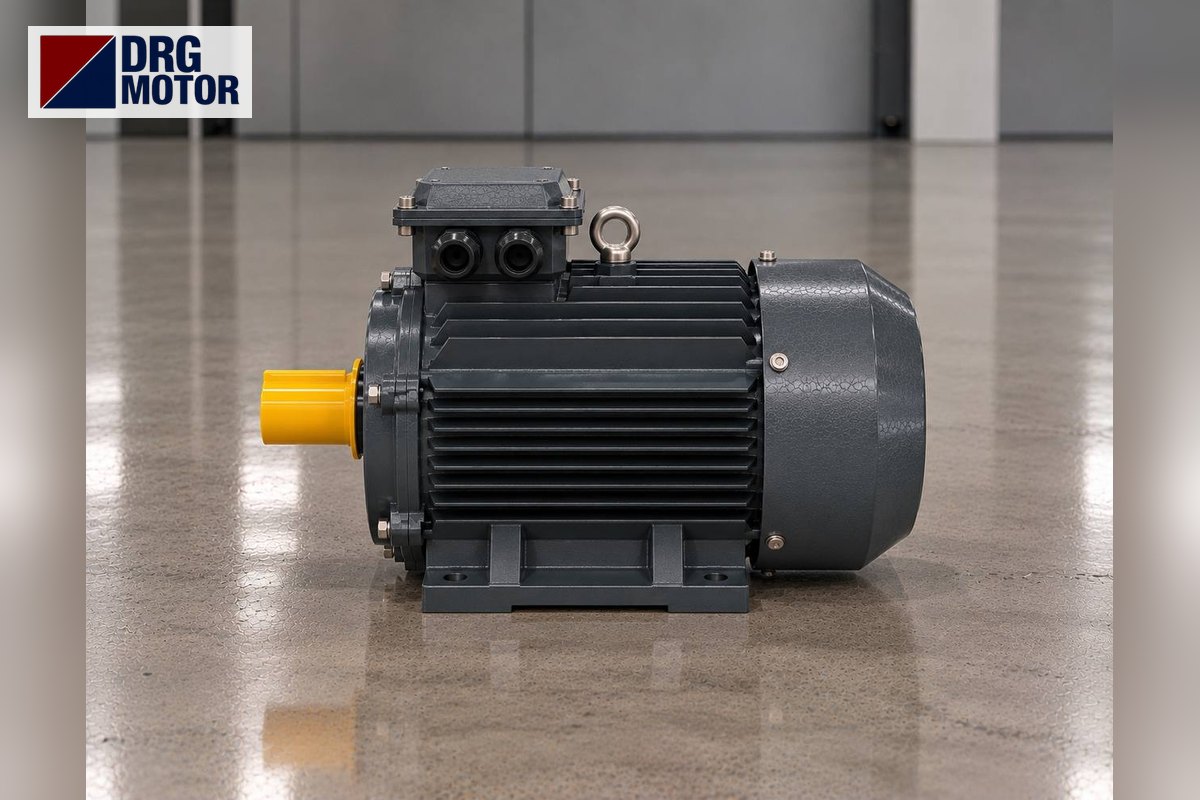

With two-location start-stop control, one motor can be started and stopped from two different places, typically the panel door and the machine itself. The rule is simple: the stop buttons (NC) are wired in series, while the start buttons (NO) are wired in parallel together with the K1 self-holding contact 13-14. Any start button can then run the motor and any stop button can stop it.
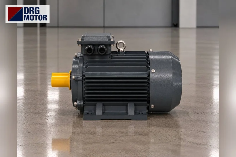
Safety notice: This content is for technical information only. Wiring, measurement and commissioning must be carried out by qualified electrical personnel, following lock-out and verification of de-energised state, and in line with the motor and device manufacturer's documentation.
Why control a motor from two places?
The control panel is often in an electrical room or on a wall some distance away, while the operator stands next to the conveyor, mixer or fan. Walking back to the panel for every start wastes time, and, more importantly, the operator cannot stop the motor straight away if something goes wrong at the machine. A second push-button station closes that gap: maintenance staff use the panel, the operator uses the station at the machine.
The basis is the familiar start-stop self-holding circuit. Pressing start energises K1, its auxiliary contact 13-14 bridges the start button and keeps the coil energised after the button is released. Pressing stop breaks that path and K1 drops out. Two-location control keeps this logic and simply adds a second button of each kind.
Power circuit: same as single-location control
The motor current path does not depend on how many control stations there are. L1, L2 and L3 pass through the F1 fuses (or a motor protection circuit breaker), the K1 main poles 1-2, 3-4, 5-6 and the F2 overload relay before reaching motor terminals U1, V1, W1. The motor frame is earthed with the PE conductor. The F2 auxiliary contact 95-96 is taken into the control circuit; on overload it opens and drops out K1.
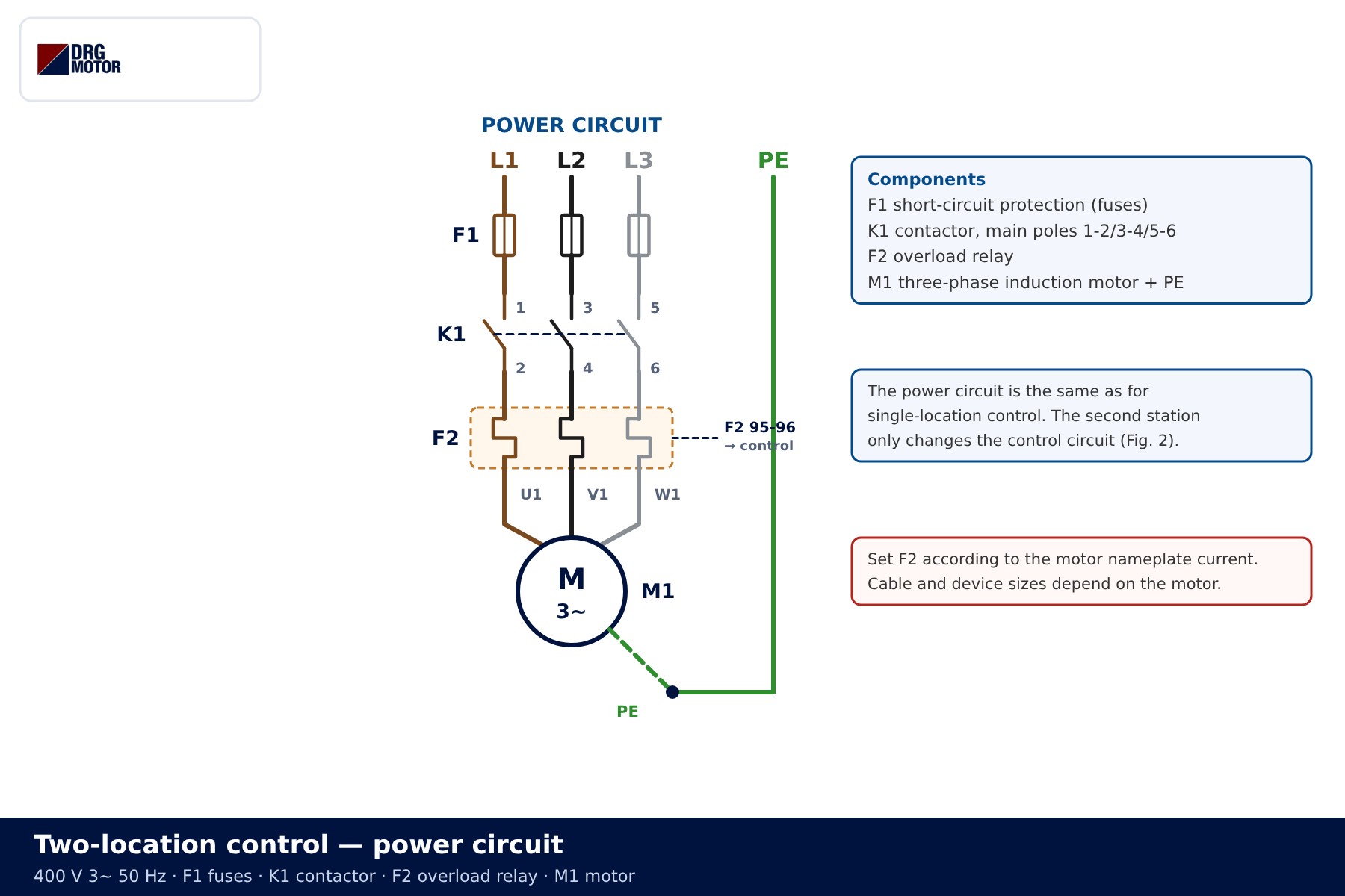
Fuses, contactor and overload relay are sized from the motor nameplate current. The overload, fuse and contactor selection tool and the motor current chart help with this; contactor sizing is covered in more detail in motor panel contactor selection.
Control circuit: stops in series, starts in parallel
The control circuit shown runs on 230 V AC: the top rail is L1 (protected by F3), the bottom rail is N. From top to bottom the current passes through:
- F2 overload contact 95-96 (NC)
- S11 local stop 11-12 (NC)
- S12 remote stop 11-12 (NC)
- Parallel block: S21 local start 13-14, S22 remote start 13-14 and K1 holding contact 13-14 (all NO)
- K1 coil A1-A2
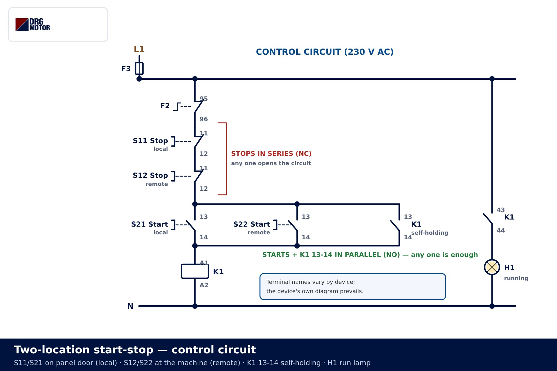
Contacts in series behave like an AND: the coil can only be energised if the overload contact, the local stop and the remote stop are all closed. Opening any one of them breaks the circuit. Contacts in parallel behave like an OR: S21, S22 or K1 13-14 closing is enough to feed the coil. Lamp H1 on the right is fed through K1 contact 43-44 and shows that the motor is running.
The position of the holding contact matters: K1 13-14 is connected to the same two points as the start buttons, i.e. below the stops. The holding path is therefore fed through the stops too, and it drops out as soon as a stop is pressed.
📄 Download Wiring Diagram PDF A4 printable PDF of the diagrams and tables (no sign-up)
Component list
| Component | Contact / terminals | Location | Function |
|---|---|---|---|
| F1 fuses | — | Panel | Short-circuit protection of the power line |
| K1 contactor | 1-2/3-4/5-6, 13-14, 43-44, A1-A2 | Panel | Switches the motor, self-holding, lamp |
| F2 overload relay | 95-96 (NC) | Panel | Opens the control circuit on overload |
| F3 control fuse | — | Panel | Protects the control circuit |
| S11 stop / S21 start | 11-12 NC / 13-14 NO | Panel door (local) | Stop and start from the panel |
| S12 stop / S22 start | 11-12 NC / 13-14 NO | At the machine (remote) | Stop and start from the machine |
| H1 lamp | via K1 43-44 | Panel door | Run indication |
Terminal names vary by device; the device's own wiring diagram prevails. The terminal numbers used here are a common example convention.
Click to see current electric motor prices and order nowSEE PRICES →
Station layout and number of cable cores
The local station usually sits in the push-button holes of the panel door. The remote station is a two-button enclosure mounted next to the machine. How many cores the cable between them needs follows directly from the way the buttons are wired.
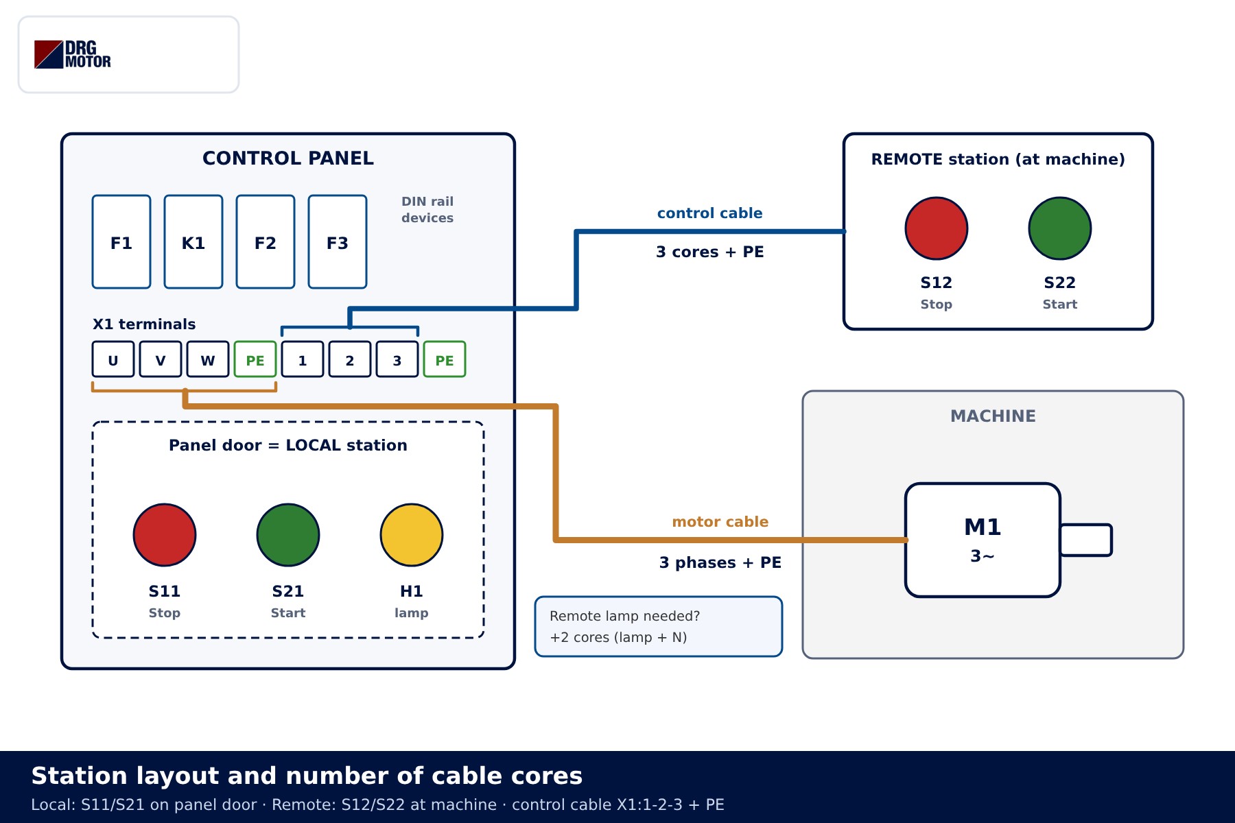
The cable to the remote box carries three points: the incoming stop line, the common point between stop output and start input, and the start output. Inside the remote box, terminal 12 of S12 is jumpered to terminal 13 of S22, so three cores serve both buttons. If the box is metallic or the cable has a protective conductor, PE is connected as well, so in practice a "3 cores + PE" cable is used.
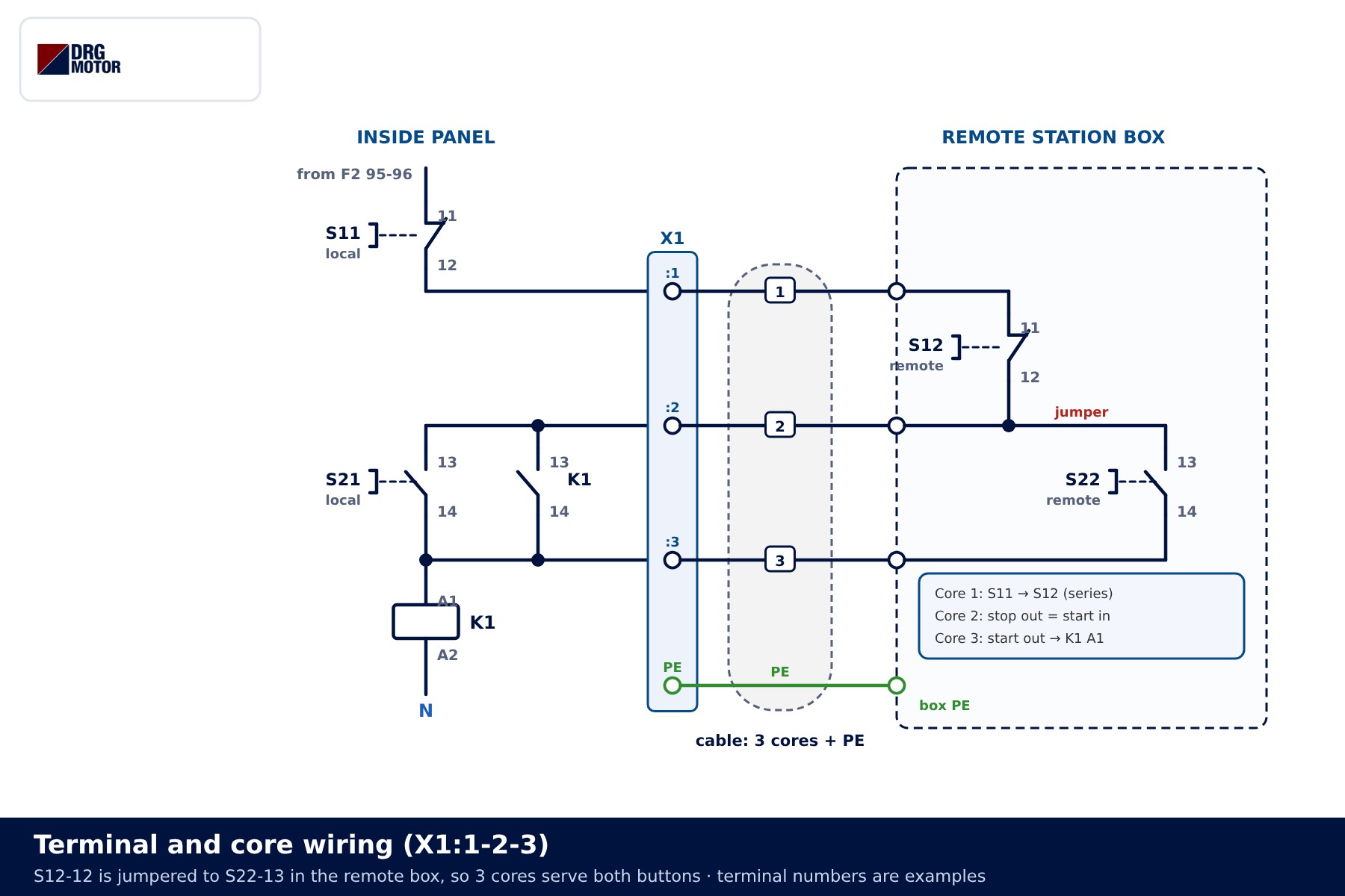
| Core | Panel terminal | Remote box | Signal |
|---|---|---|---|
| 1 | X1:1 ← S11-12 | S12-11 | Stop line in |
| 2 | X1:2 → S21-13, K1-13 | S12-12 + S22-13 jumper | Stop out = start in |
| 3 | X1:3 → K1 A1 | S22-14 | Start out |
| PE | PE terminal | Box earth | Protective conductor |
If a run lamp is also wanted at the remote station, add one core for the lamp feed and one for N. Control current is small, so the control cable is usually thinner than the motor cable, but on long runs voltage drop and cable capacitance should be checked separately. For the motor cable itself, use the motor cable size calculator.
Operating sequence step by step
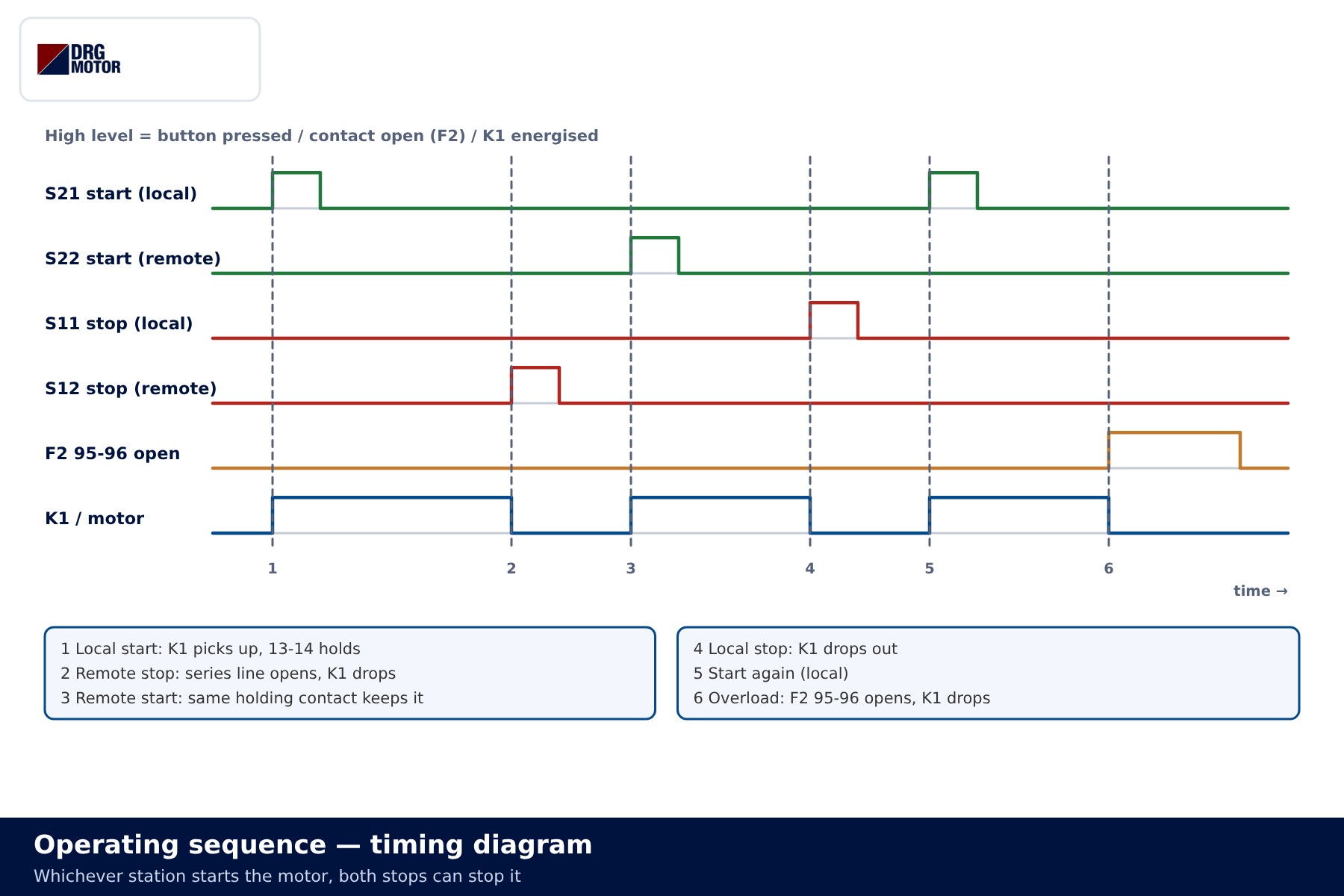
- Local start (S21): S21 closes in the parallel block and the K1 coil is energised. The main poles connect the motor, 13-14 closes and holds the coil when S21 is released. H1 lights up.
- Remote stop (S12): S12 opens in the series line, the coil loses supply and K1 drops out. Since 13-14 also opens, releasing the button does not restart the motor.
- Remote start (S22): S22 closes and K1 holds in through the same 13-14 contact. It does not matter which start was used.
- Local stop (S11): S11 opens and the motor stops.
- Overload: F2 trips, contact 95-96 breaks the line and K1 drops out. No start button can run the motor until the overload relay is reset.
State table
| State | Series line (F2, S11, S12) | Parallel block | K1 / motor |
|---|---|---|---|
| Idle | Closed | All open | Dropped out / stopped |
| S21 or S22 pressed | Closed | Pressed start closed | Picks up / runs |
| Start released | Closed | K1 13-14 closed | Held in / runs |
| S11 or S12 pressed | Open | No effect | Drops out / stops |
| F2 tripped | Open | No effect | Drops out / stops |
Common wiring mistakes
Most faults found on site come from mixing up series and parallel.
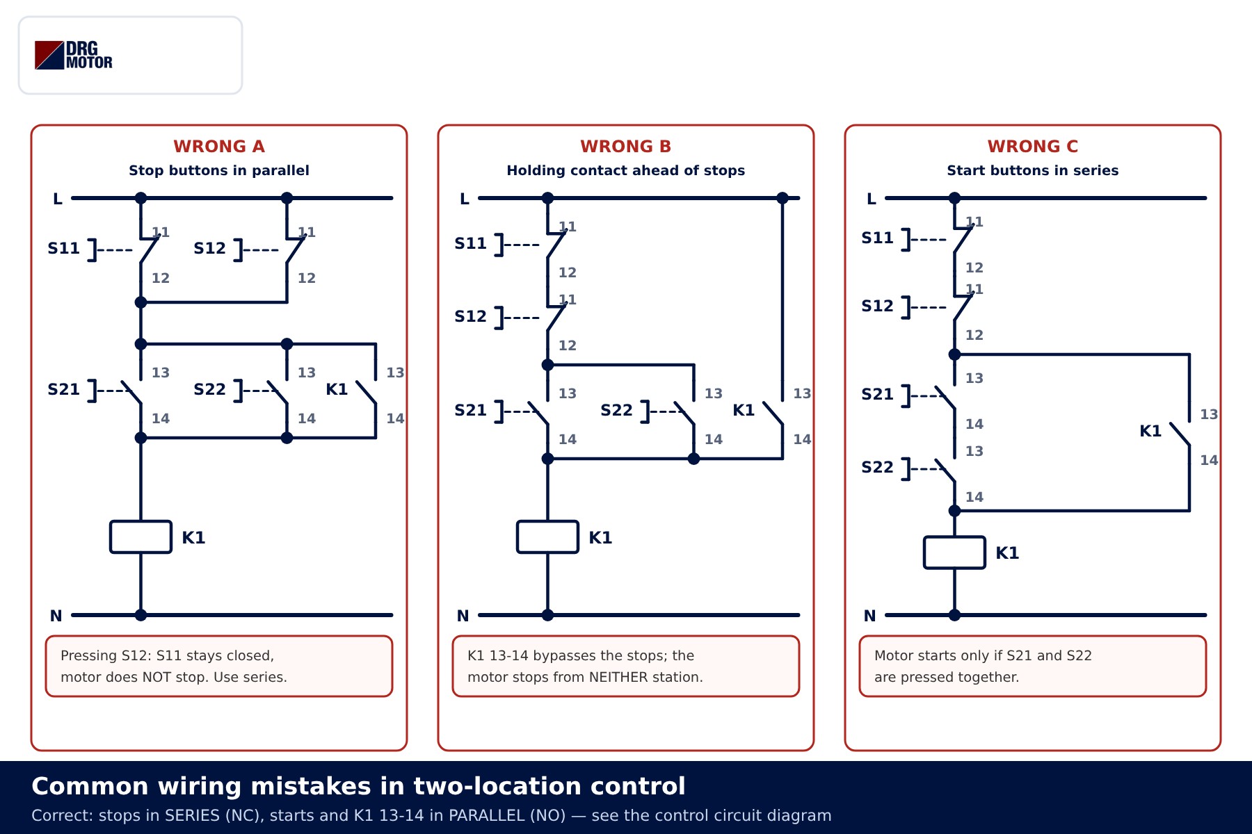
| Symptom | Likely cause | Check |
|---|---|---|
| One station's stop does not stop the motor | Stop buttons wired in parallel | Are S11 and S12 one after the other on the same line? |
| Neither stop button stops the motor | K1 13-14 fed straight from the L rail | Is the holding contact connected below the stops? |
| Motor only starts when both starts are pressed | Start buttons wired in series | Are S21 and S22 across the same two points? |
| Motor stops when start is released | No holding contact, or NC terminals used | Is K1 13-14 (NO) in the parallel branch? |
| Remote start works, remote stop does not | Wrong jumper in the remote box or cores swapped | Check cores 1-2-3 end to end |
Another frequent mistake is landing the cores of the remote cable on different terminals at the panel end. Mark core numbers or colours in the same order at both ends and test continuity with the circuit de-energised.
Emergency stop is not shown in this circuit. An emergency stop is not treated as an ordinary stop button; the safety function is designed separately on the basis of a risk assessment.
Three or more stations
The same rule holds as stations are added: every new stop button becomes one more link in the series line, every new start button one more branch in the parallel block. Each extra station is again fed with three cores, and the boxes can be daisy-chained. For reversing duty the same logic applies to the forward and reverse start buttons; interlocking is explained in three-phase motor forward-reverse contactor wiring, and timed starting in the star-delta control circuit article.
Selection examples
Example 1 – belt conveyor, 1.5 kW: the panel is in a corner, the operator works at the far end of the belt. The local station goes on the panel door, the remote one at the head of the conveyor, linked by a 3-core + PE control cable. A 230/400 V motor is connected in star on a 400 V supply.
Example 2 – ventilation fan, 4 kW: the fan is on the roof, the panel in the basement. A remote station is fitted next to the fan for servicing; a run lamp is also required, so a 5-core + PE cable is chosen. A 400/690 V motor is connected in delta on a 400 V supply.
In both cases the protective devices and cable cross-section are chosen from the motor nameplate, run length and installation method.
Send a photo of your current motor nameplate and we will find the suitable DRG model together.Send on WhatsApp
DRG motors suited to two-location control
DRG Motor is an electric motor manufacturer, supplier and seller. The three-phase induction motors below suit direct-on-line starting with a contactor and two-location start-stop control. Contactors, overload relays and push buttons are not sold by DRG; please source them from your panel equipment supplier. Other ratings and speeds are listed under three-phase asynchronous electric motors and in the online store.
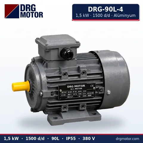
1.5 kW Three-Phase Motor 1500 rpm – DRG-90L-4 Aluminium
- 1.5 kW · 1500 rpm (4 poles)
- Aluminium frame · IEC 90L
- Mounting: B3 · B5 · B14 · B35
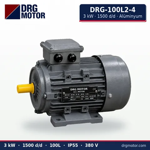
3 kW Three-Phase Motor 1500 rpm – DRG-100L2-4 Aluminium
- 3 kW · 1500 rpm (4 poles)
- Aluminium frame · IEC 100L
- Mounting: B3 · B5 · B14 · B35
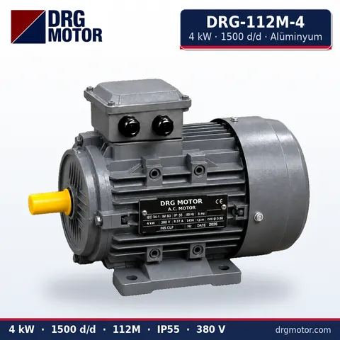
4 kW Three-Phase Motor 1500 rpm – DRG-112M-4 Aluminium
- 4 kW · 1500 rpm (4 poles)
- Aluminium frame · IEC 112M
- Mounting: B3 · B5 · B14 · B35
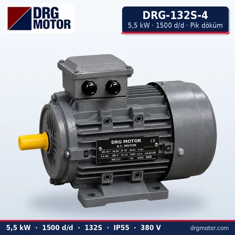
5.5 kW Three-Phase Motor 1500 rpm – DRG-132S-4 Cast Iron
- 5.5 kW · 1500 rpm (4 poles)
- Cast iron frame · IEC 132S
- Mounting: B3 · B5 · B14 · B35
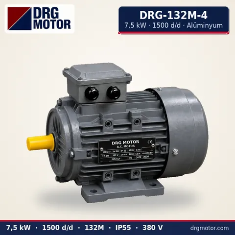
7.5 kW Three-Phase Motor 1500 rpm – DRG-132M-4 Aluminium
- 7.5 kW · 1500 rpm (4 poles)
- Aluminium frame · IEC 132M
- Mounting: B3 · B5 · B14 · B35
Click to see current prices for these motors and order nowSEE PRICES →
Frequently asked questions
Why are the stop buttons wired in series?
Because each stop button must be able to stop the motor on its own. Opening one NC contact in a series line breaks the whole line. In parallel, the other button would keep carrying current and the motor would keep running.
How many cores does the remote station need?
Three cores are enough for one stop and one start button, plus PE if the box is metallic. A remote run lamp needs two more cores.
Does each start button need its own K1 13-14 contact?
No. A single 13-14 contact is placed across the same two points as both start buttons. Whichever start is pressed, the same contact holds the circuit in.
Where is the overload relay reset after a trip?
The overload relay sits inside the panel, so it is normally reset there. Find and remove the cause first; after reset the motor only starts again with a new start command.





