 English
 Le français
 Türkçe





In a delayed motor start with a timer relay, pressing the start button does not start the motor at once: the on-delay timer KT is energised first, and only when the set time has elapsed does its delayed NO contact close and the K1 contactor connect the motor to the supply. A self-holding circuit keeps the sequence alive, and if stop is pressed before the time is up, K1 never picks up. This article explains it with the power circuit, control circuit, timing diagram and two practical examples.
⚠ This content is for technical information only. Wiring, measurement and commissioning must be carried out by qualified electrical personnel, following lock-out and verification of de-energised state, and in line with the motor and device manufacturer's documentation.
Why delay a motor start?
On some machines the motor should turn not at the moment of the command but after a preparation period. Typical reasons: an auxiliary device (fan, lubrication, cooling) must reach steady operation first; people nearby must be warned by a lamp or horn; several motors in the same panel should not draw their starting currents at the same time. A single on-delay timer handles all of this. Nothing changes in the power circuit; what changes is when the K1 coil receives voltage.
Timers are also used to set the star-to-delta changeover. That circuit involves three contactors and interlocking, so it is covered separately in the star-delta control circuit article. Here we deal with a single-contactor, direct-on-line motor.
Power and control circuits
Power circuit: the timer is not in it
The power circuit is an ordinary direct-on-line starter. L1, L2 and L3 pass through the Q1 motor protection breaker, enter the K1 main contacts (1-2, 3-4, 5-6), run through the heaters of overload relay F2 and reach motor terminals U1, V1, W1. The motor frame is bonded to PE. The KT timer carries no motor current; it only controls the K1 coil.
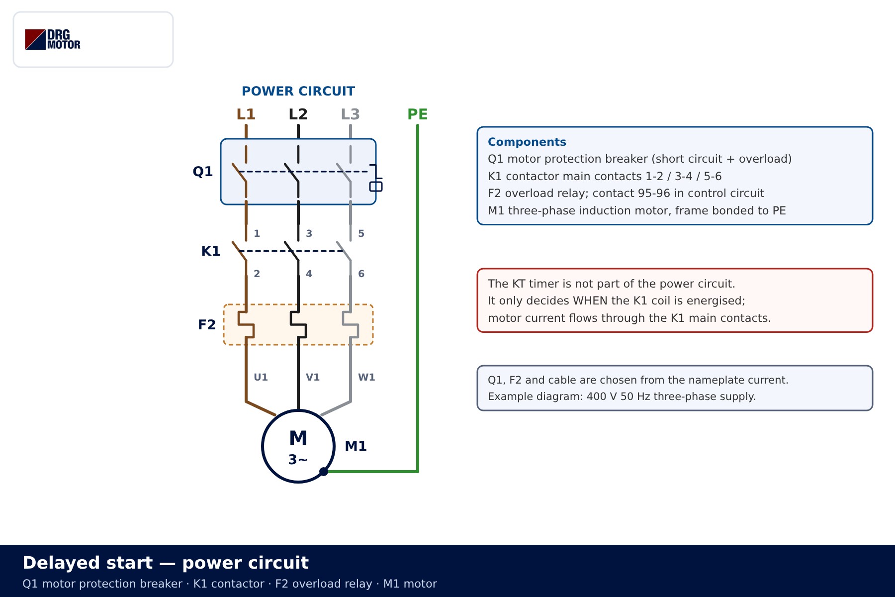
Q1, F2, K1 and the cable size are chosen from the rated current on the motor nameplate. The motor current chart and the overload, fuse and contactor selection tool give a starting point; the reasoning behind contactor sizing is in motor panel contactor selection.
Control circuit components
The control circuit is a vertical ladder supplied at 230 V AC: L rail on top, N rail at the bottom. The series chain holds the control fuse, the overload contact and the stop button. The start button and the holding contact are wired in parallel and feed a common node, from which four rungs drop down.
| Device | Contact / terminals | Role |
|---|---|---|
| F3 | Control fuse | Protects the control circuit against short circuits |
| F2 | NC 95-96 | Opens on overload and cuts the whole control circuit |
| S0 stop | NC 11-12 | Opens the circuit when pressed |
| Start butonu | NO 13-14 | Energises the KA1 and KT coils when pressed |
| KA1 | Coil A1-A2 + NO 13-14 | Auxiliary relay; holds the circuit after start is released |
| KT | Coil A1-A2 + delayed NO 15-18 | Times the delay and closes the K1 rung at the end |
| K1 | Coil A1-A2 + NC 21-22 | Connects the motor; its NC contact switches off the waiting lamp |
| H1 | Lamp | Shows “timing in progress, motor will start shortly” |
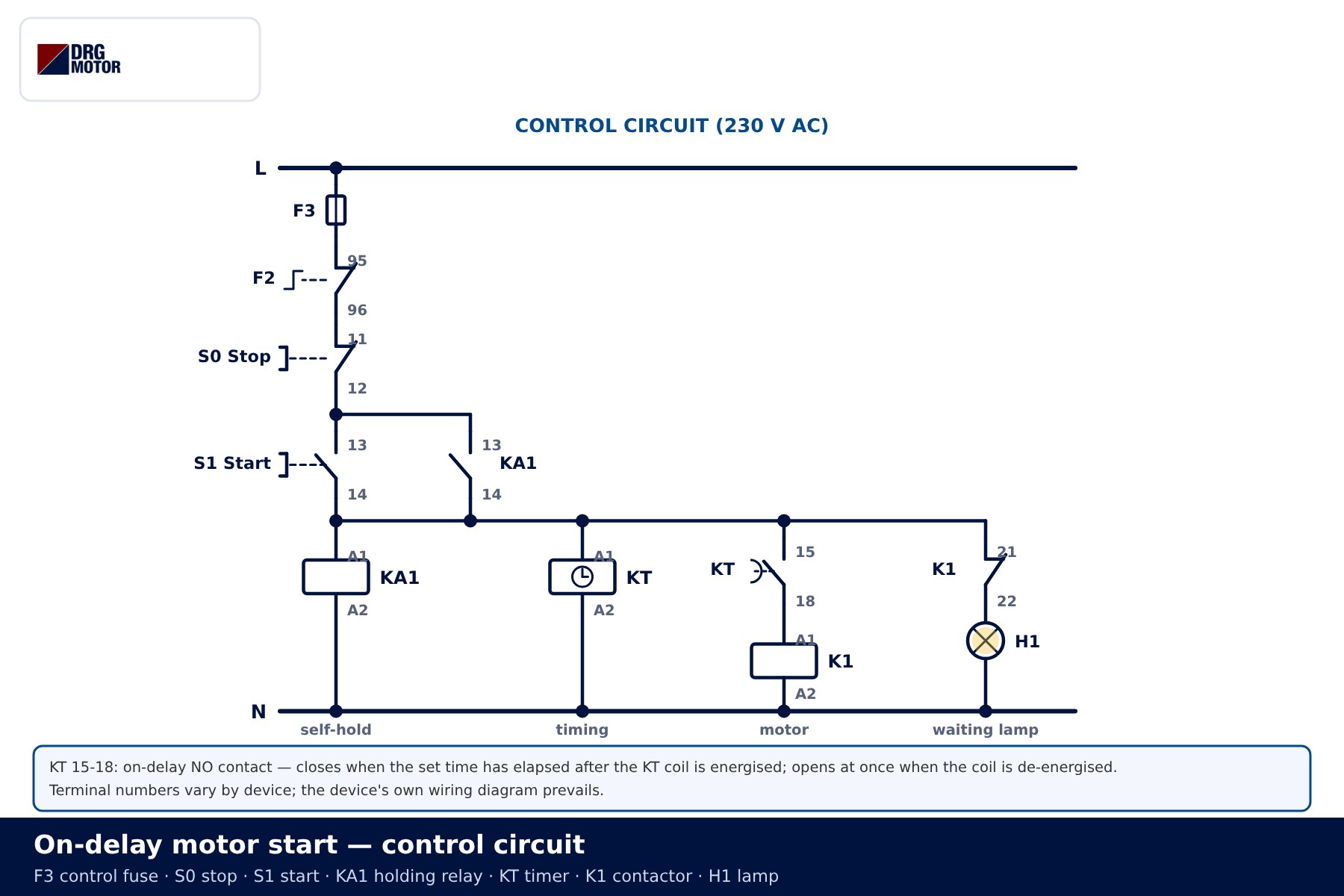
The holding contact comes from a separate auxiliary relay (KA1), not from K1. The reason is simple: K1 only picks up at the end of the delay. If the hold relied on K1, the operator would have to keep the start button pressed for the whole delay. KA1 picks up and latches the moment the button is pressed, while KT counts. Terminal numbers vary by device; the device's own wiring diagram prevails.
📄 Download Wiring Diagram PDF A4 printable PDF of the diagrams and tables (no sign-up)
Click to see current electric motor prices and order nowSEE PRICES →
Step-by-step operation
- Start is pressed: current flows through F3, F2 95-96 and the stop button to the common node. KA1 and KT are energised together. Because K1 21-22 is closed, H1 lights.
- The button is released: KA1 13-14 is now closed, so the node stays live and KT keeps timing. The motor is still at rest.
- The time is up: KT 15-18 closes, the K1 coil is energised, the main contacts close and the motor starts. K1 21-22 opens and H1 goes out.
- Stop is pressed: the series chain opens; KA1, KT and K1 drop out together. KT resets.
- The overload trips: F2 95-96 opens with the same effect as stop. Until the overload is reset, a new start command cannot energise the circuit.
- Supply fails and returns: the hold has been lost, so the motor does not restart on its own; a new start command is needed.
Timing diagram and state table
The diagram shows two cycles. In the first, the delay runs out and the motor starts. In the second, the operator presses stop before the end of the delay: the KT contact never closes, K1 stays off and the next start counts from zero.
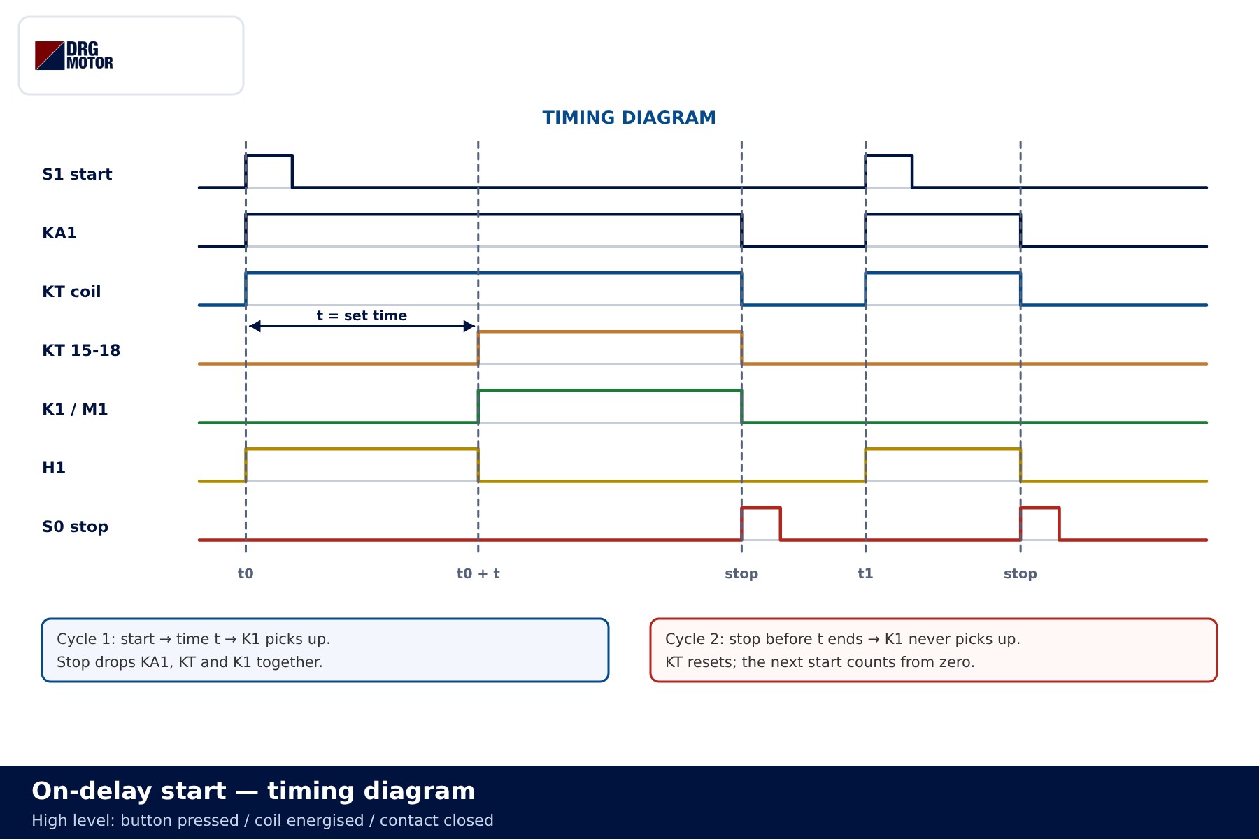
| State | KA1 / KT coil | KT 15-18 | K1 / motor |
|---|---|---|---|
| Idle | De-energised | Open | Dropped out / stopped |
| Start pressed, timing | Energised | Open | Dropped out / stopped (H1 on) |
| Delay elapsed | Energised | Closed | Picked up / running |
| Stop or overload trip | De-energised | Open (reset) | Dropped out / stopped |
On-delay versus off-delay
With an on-delay timer, the delay starts when the coil is energised; the contact closes at the end of the delay and opens immediately when the supply is removed. An off-delay timer works the other way round: the contact closes straight away with the command, the delay begins once the command is removed, and the contact opens at the end. In the symbol, the direction of the half-circle attached to the contact shows which type it is.
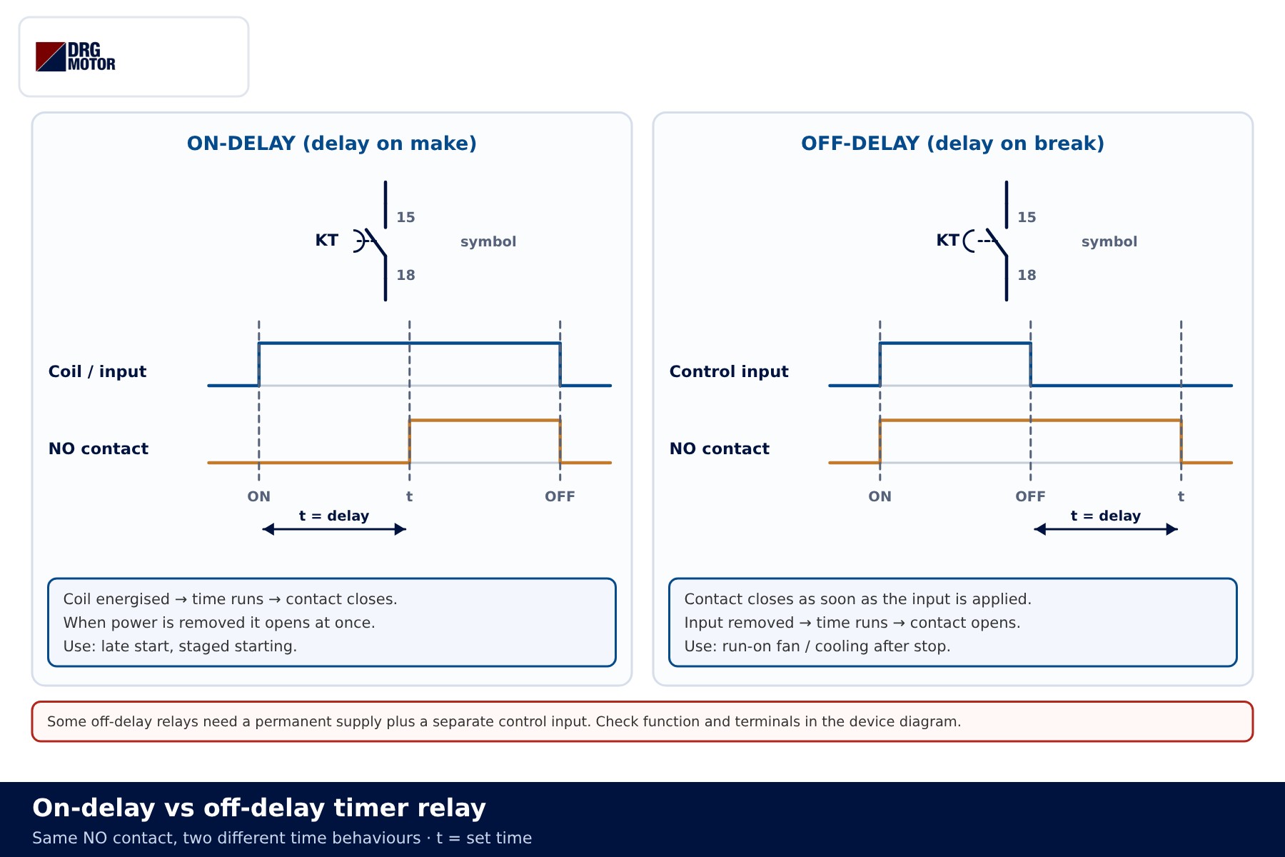
A request such as “keep the fan running for a while after the motor stops” needs an off-delay relay; the request in this article, “start the motor after a while”, is an on-delay job. Some off-delay relays require a permanent supply plus a separate control input. With multi-function relays, check during commissioning that the correct function is selected.
Application examples
Fan first, then pump: the fan contactor K1 runs from its own start-stop circuit. K1 contact 13-14 feeds the KT coil; when the delay ends, KT 15-18 picks up the pump contactor K2. If the fan stops, KT and K2 drop out as well, so the pump cannot run without the fan.
Start after a warning period: on a long conveyor, a lamp or horn warns before start-up. The NC side (15-16) of the KT changeover contact drives warning device H1 during the delay; the NO side (15-18) picks up K1 when the time is up. Because warning and start come from the same contact, they can never overlap.
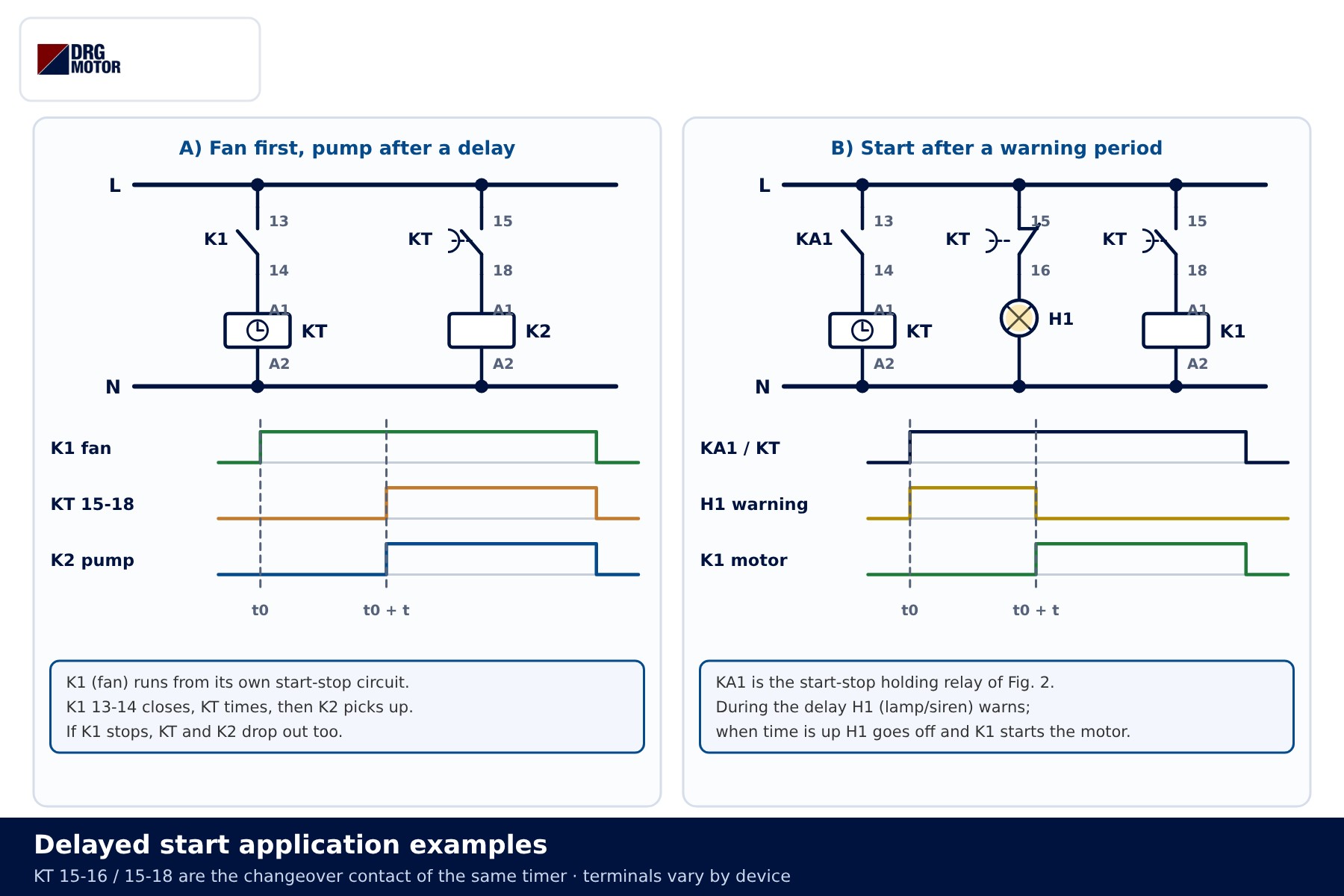
The delay value depends on the application: it is set on site by observing how long the fan needs to settle, how long the warning needs to be noticed, or how long the previous motor's starting current takes to fall. No single value suits every plant. If the warning period is part of a safety measure, the function must be designed according to the risk assessment.
Common wiring mistakes
- Motor starts as soon as start is pressed → wired to the instantaneous contact of KT, the wrong function selected on a multi-function relay, or 15-16 used instead of 15-18.
- KT resets when the button is released → the hold is taken from K1, or KA1 13-14 is not in parallel with the start button.
- Delay ends but K1 does not pick up → open circuit between the KT output contact and K1 A1, K1 A2 not returned to the N rail, or a coil voltage that does not match the control voltage.
- KT never times → supply terminals and contact terminals mixed up; on some relays the supply is applied to separate terminals.
- Motor restarts by itself after an overload trip → F2 set to automatic reset and the hold wired ahead of F2. Contact 95-96 must sit inside the series chain. The logic of overload setting is explained in what an overload relay does.
Selection examples
A delayed start does not change anything in the motor itself; the motor is still started direct-on-line. The usual direct-on-line rules on starting current, supply capacity and contactor rating therefore apply. DRG motors up to 3 kW are wound 230/400 V, those of 4 kW and above 400/690 V; on a 400 V supply the first are connected in star, the second in delta. Where direct-on-line starting would stress the supply at higher ratings, consider star-delta or another starting method rather than a delay. Selection is based on the nameplate current, speed and mounting; the full range is on the three-phase asynchronous electric motors page.
Send a photo of your current motor nameplate and we will find the suitable DRG model together.Send on WhatsApp
DRG motors suited to delayed starting
DRG Motor is an electric motor manufacturer, supplier and seller. The three-phase models below sit in the power range commonly used for fans, pumps and conveyors where a delayed start is wanted. Timers, contactors, overload relays and push buttons are not sold by DRG; please source them from your panel equipment supplier. Other ratings and speeds are listed in the online store.
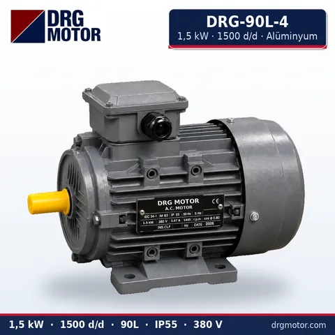
1.5 kW Three-Phase Motor 1500 rpm – DRG-90L-4 Aluminium
- 1.5 kW · 1500 rpm (4 poles)
- Aluminium frame · IEC 90L
- Mounting: B3 · B5 · B14 · B35
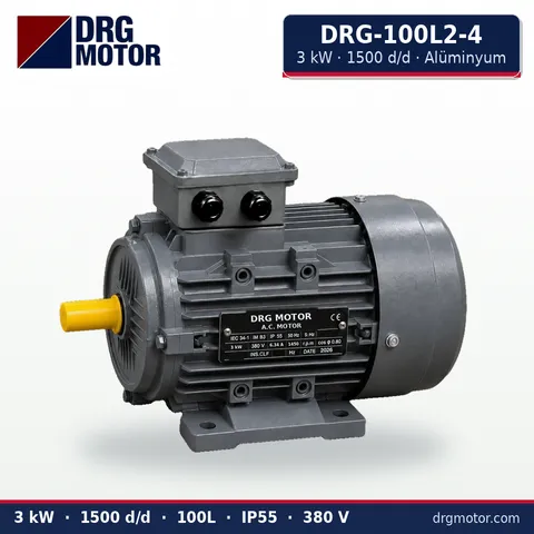
3 kW Three-Phase Motor 1500 rpm – DRG-100L2-4 Aluminium
- 3 kW · 1500 rpm (4 poles)
- Aluminium frame · IEC 100L
- Mounting: B3 · B5 · B14 · B35
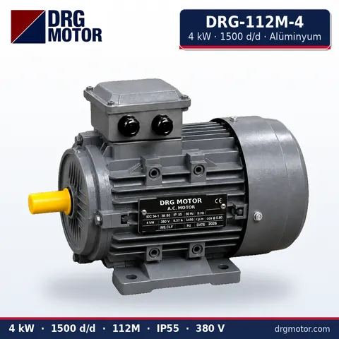
4 kW Three-Phase Motor 1500 rpm – DRG-112M-4 Aluminium
- 4 kW · 1500 rpm (4 poles)
- Aluminium frame · IEC 112M
- Mounting: B3 · B5 · B14 · B35
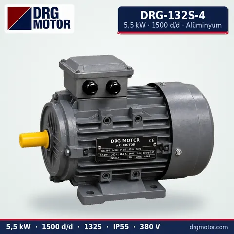
5.5 kW Three-Phase Motor 1500 rpm – DRG-132S-4 Aluminium
- 5.5 kW · 1500 rpm (4 poles)
- Aluminium frame · IEC 132S
- Mounting: B3 · B5 · B14 · B35
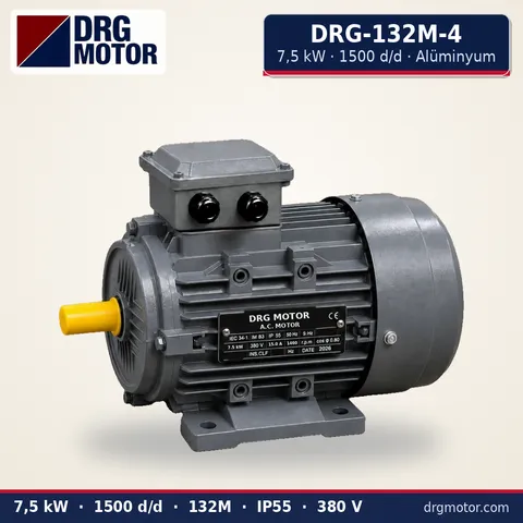
7.5 kW Three-Phase Motor 1500 rpm – DRG-132M-4 Aluminium
- 7.5 kW · 1500 rpm (4 poles)
- Aluminium frame · IEC 132M
- Mounting: B3 · B5 · B14 · B35
Click to see current prices for these motors and order nowSEE PRICES →
Frequently asked questions
Why use a separate relay for self-holding instead of K1?
K1 does not pick up until the delay is over, so its holding contact would not close before then either. A separate auxiliary relay (KA1) latches the moment start is pressed and lets KT complete the delay.
What delay should the timer be set to?
There is no fixed figure. The delay is set on site according to the time the upstream equipment needs to be ready or the warning needs to be noticed; the setting range and method are given in the device's own documentation.
What happens if I press stop before the delay ends?
KA1 and KT drop out, KT resets and K1 never picks up. The next start counts the delay from zero.
Can an off-delay relay do the same job?
No. An off-delay relay closes its contact immediately and applies the delay at switch-off. To start a motor late you need the on-delay function.
Will the motor restart by itself after a power cut?
Not with this circuit: when the supply is lost KA1 drops out and the hold is released. A new press of the start button is required.
📄 Download Wiring Diagram PDF A4 printable PDF of the diagrams and tables (no sign-up)





