 English
 Le français
 Türkçe





To run two motors in sequence, a normally open auxiliary contact of the first motor's contactor is wired in series with the coil branch of the second contactor. K2 then cannot be energised unless K1 is closed, and if M1 stops on an overload, M2 drops out automatically. The order can be set manually with two start buttons or automatically with a timer relay.
⚠ This content is for technical information only. Wiring, measurement and commissioning must be carried out by qualified electrical personnel, following lock-out and verification of de-energised state, and in line with the motor and device manufacturer's documentation.
This arrangement is typical for conveyor lines, feeder–crusher pairs, lubrication pump–main drive combinations and any machine where one drive must be running before the other is allowed to start. Below you will find the power circuit, two control solutions, a timing diagram, a state table and a two-belt conveyor example.
Why start motors in sequence?
Starting both motors at the same moment causes two kinds of trouble. The first is process-related: if the feeding belt runs before the receiving belt moves, material piles up at the transfer point, the belt slips or spills. The second concerns the supply: every direct-on-line induction motor draws several times its rated current while starting. When two inrush currents overlap, the voltage dip grows and protective devices may trip for no real fault. A staggered start solves both: M1 starts and settles, then M2 follows.
The key idea is that the order does not rely on the operator. The sequence condition is built into the control circuit electrically, so M2 will not run without M1 even if the wrong button is pressed.
Power circuit: separate protection and contactor per motor
On the power side the two motors are independent. M1 is fed through motor protection breaker Q1 and contactor K1; M2 through Q2 and K2. Each breaker is chosen and set from the rated current on its own motor's nameplate. A shared overload device is not a good idea: an overload on the smaller motor disappears inside the larger motor's current. The difference between an overload relay and a motor protection breaker is explained in thermal relay vs motor protection breaker.
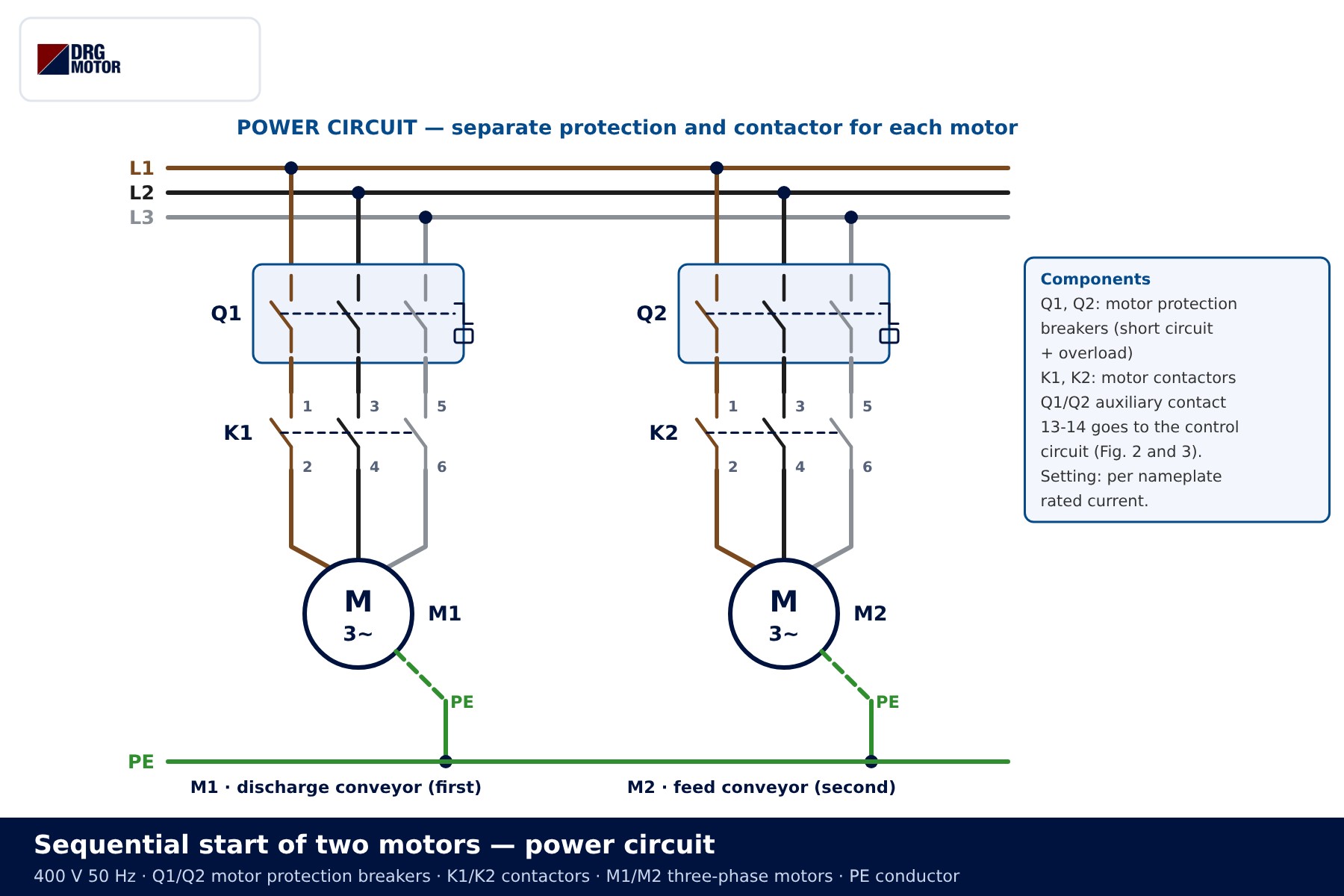
The auxiliary contact 13-14 of Q1 and Q2 is taken into the control circuit. When a breaker trips, this contact opens and the related contactor coil loses its supply; the “if M1 stops, M2 stops” logic starts from here.
Components in the circuit
| Item | Type | Function |
|---|---|---|
| Q1, Q2 | Motor protection breaker | Short-circuit and overload protection; auxiliary contact 13-14 goes to the control circuit |
| K1, K2 | Contactor | Connects M1 and M2; 13-14 self-holding, K1 23-24 sequence condition |
| F1 | Control fuse | Protects the 230 V AC control circuit |
| S0 | Stop button (NC) | Stops both motors |
| S11, S22 | Start buttons (NO) | S11 starts M1, S22 starts M2 (manual circuit) |
| S21 | Stop button (NC) | Stops M2 only |
| KT1 | On-delay timer relay | Sets the moment M2 starts in the automatic circuit |
Solution 1: manual sequence (K1 contact in the K2 branch)
In the first solution the operator uses two start buttons. The M1 branch is a standard start-stop circuit: S0, Q1 13-14, S11 with the K1 13-14 self-holding contact in parallel, then the K1 coil. In the M2 branch, after S21 stop, S22 start and K2 13-14 self-holding, a second K1 auxiliary contact, K1 23-24, is wired in series. It is drawn in red because this contact creates the sequence condition.
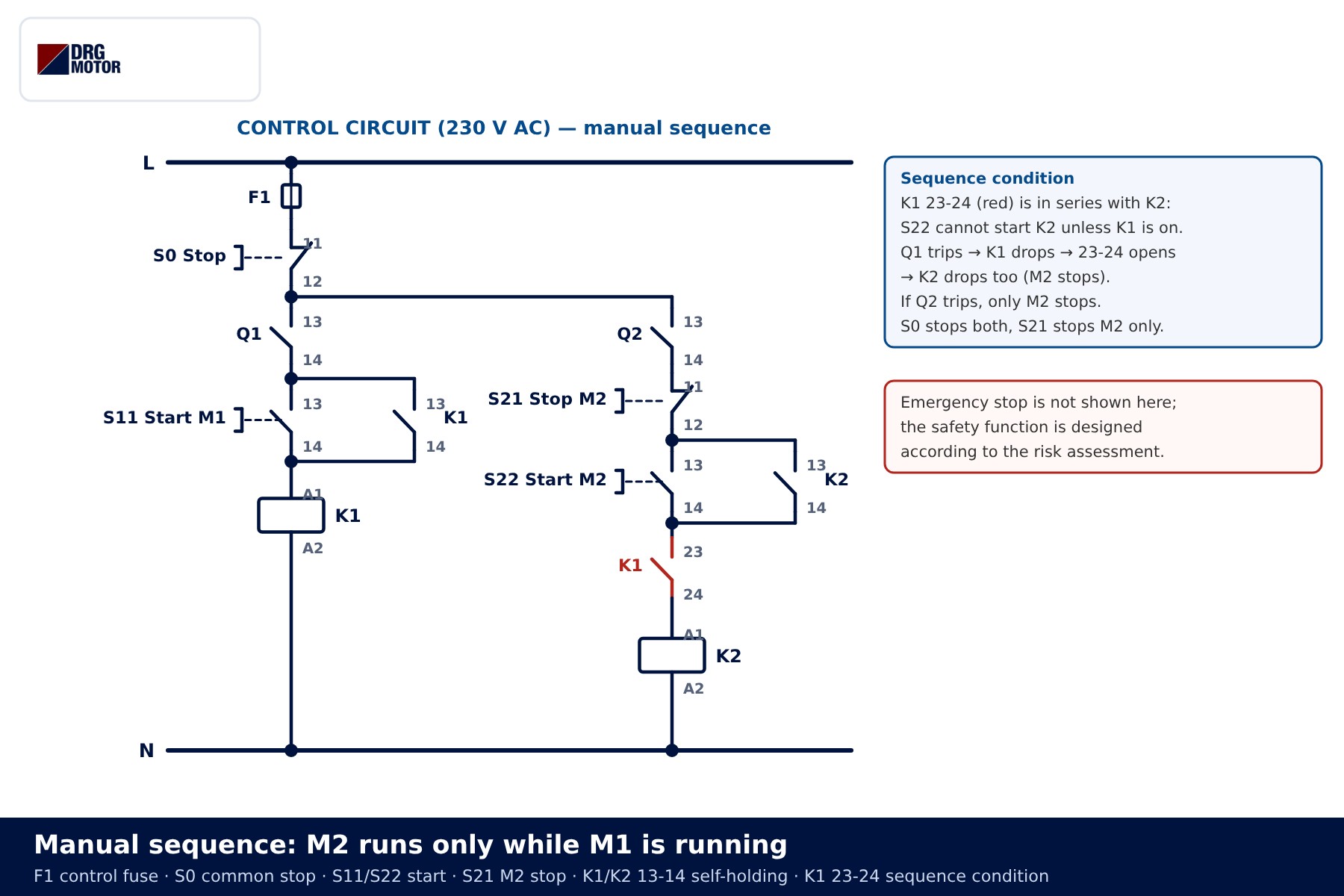
Step by step:
- S22 pressed first: K1 23-24 is open, so the K2 coil gets no voltage. M2 does not start.
- S11 pressed: K1 pulls in, holds itself via 13-14 and M1 runs. K1 23-24 closes and the M2 branch becomes “ready”.
- S22 pressed: K2 pulls in, holds via 13-14 and M2 runs.
- S21 pressed: only K2 drops out; M1 keeps running.
- S0 pressed or Q1 trips: K1 drops, K1 23-24 opens and K2 drops too. Both motors stop.
- Q2 trips: only M2 stops; M1 keeps clearing the material.
Watch the position: K1 23-24 must sit in the common path to the K2 coil, outside the self-holding loop. If it is placed only next to S22, stopping M1 will not stop M2 once K2 has latched.
📄 Download Wiring Diagram PDF A4 printable PDF of the diagrams and tables (no sign-up)
Click to see current electric motor prices and order nowSEE PRICES →
Solution 2: automatic staggered start with a timer
The second solution has a single start button and a timer relay decides when M2 starts. The common series path holds S0, Q1 13-14 and Q2 13-14, so a trip on either breaker stops the whole line. S11 energises K1, which latches. From the K1 output two branches split: one goes through K2 21-22 to the KT1 coil, the other through KT1 17-18 (with K2 13-14 in parallel) and K1 23-24 to the K2 coil.
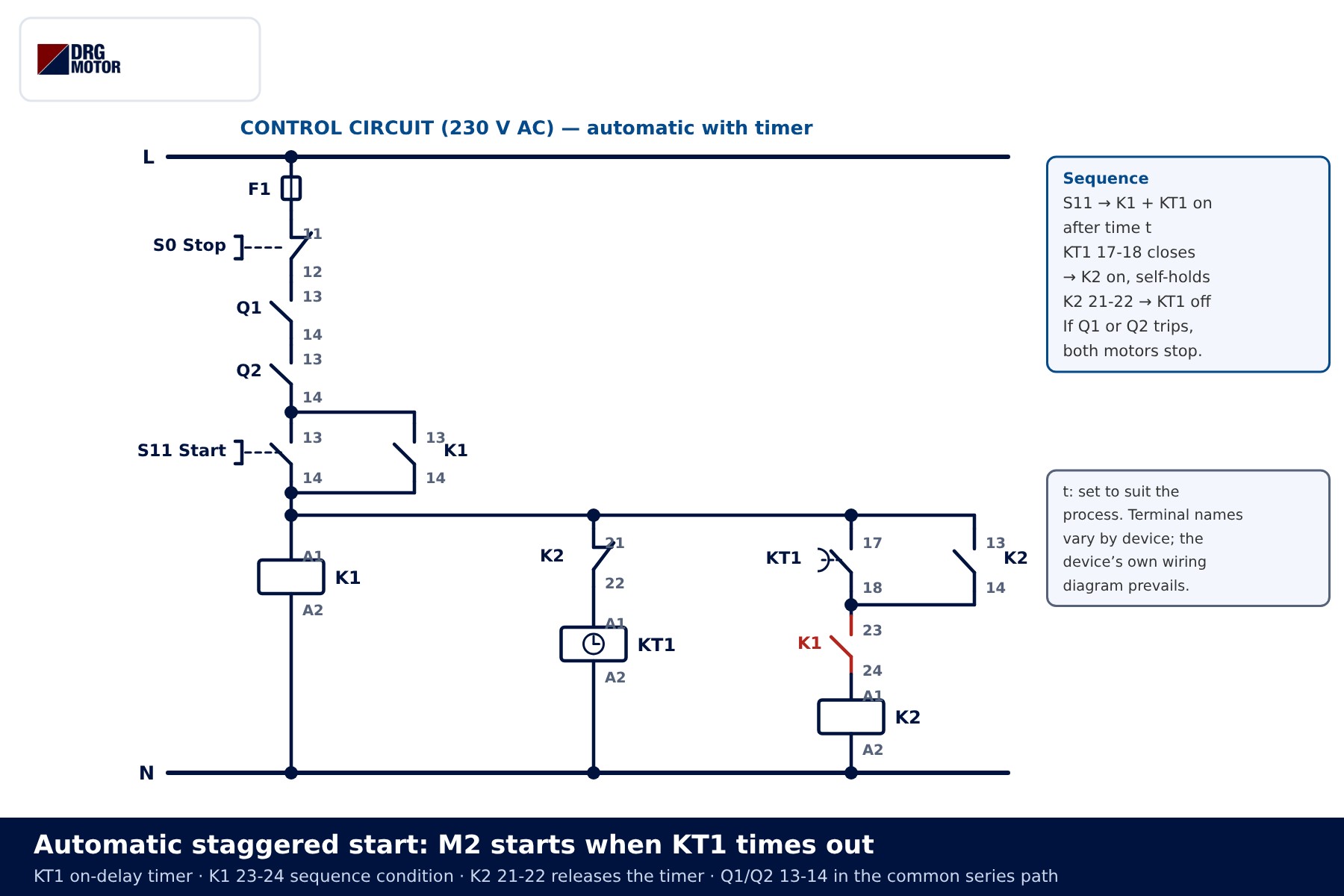
When S11 is pressed, K1 and KT1 are energised together. Once the KT1 delay has elapsed, contact 17-18 closes, K2 pulls in and latches through its own 13-14. As K2 closes, its 21-22 contact opens and de-energises the timer, so the relay is not left powered without reason. The delay is chosen so that M1 completes its start and the belt reaches conveying speed. There is no fixed figure; it is set at commissioning according to load and machine inertia. Another use of a timer relay is shown in the star-delta control circuit article.
Terminal names (A1-A2, 15-16-18, 17-18 and so on) vary by device; the device's own wiring diagram prevails.
Timing diagram and state table
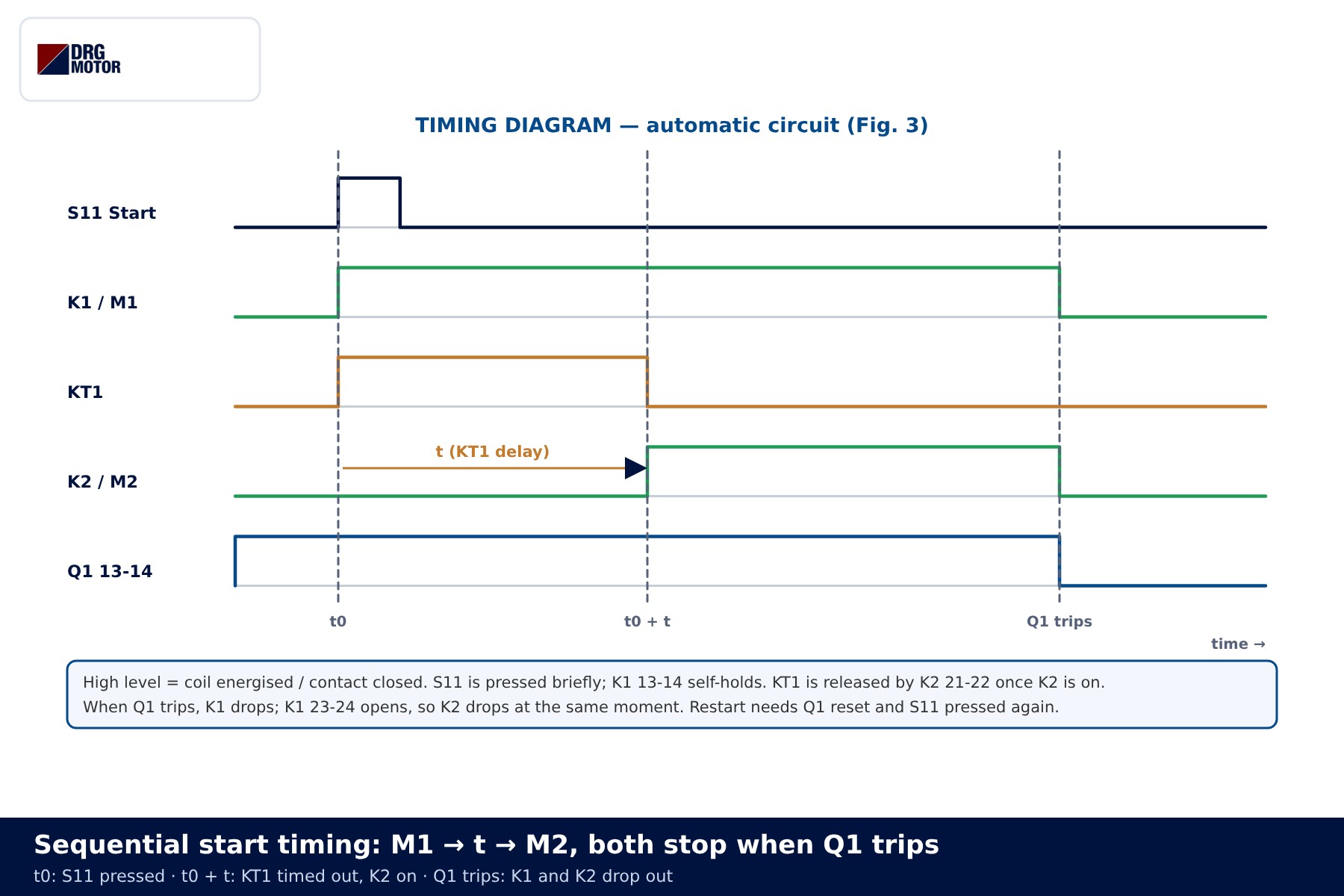
The timing diagram summarises the automatic circuit: at t0 S11 is pressed briefly and K1 and KT1 go high; at t0 + t KT1 goes low and K2 goes high. When Q1 trips, K1 and K2 fall on the same line.
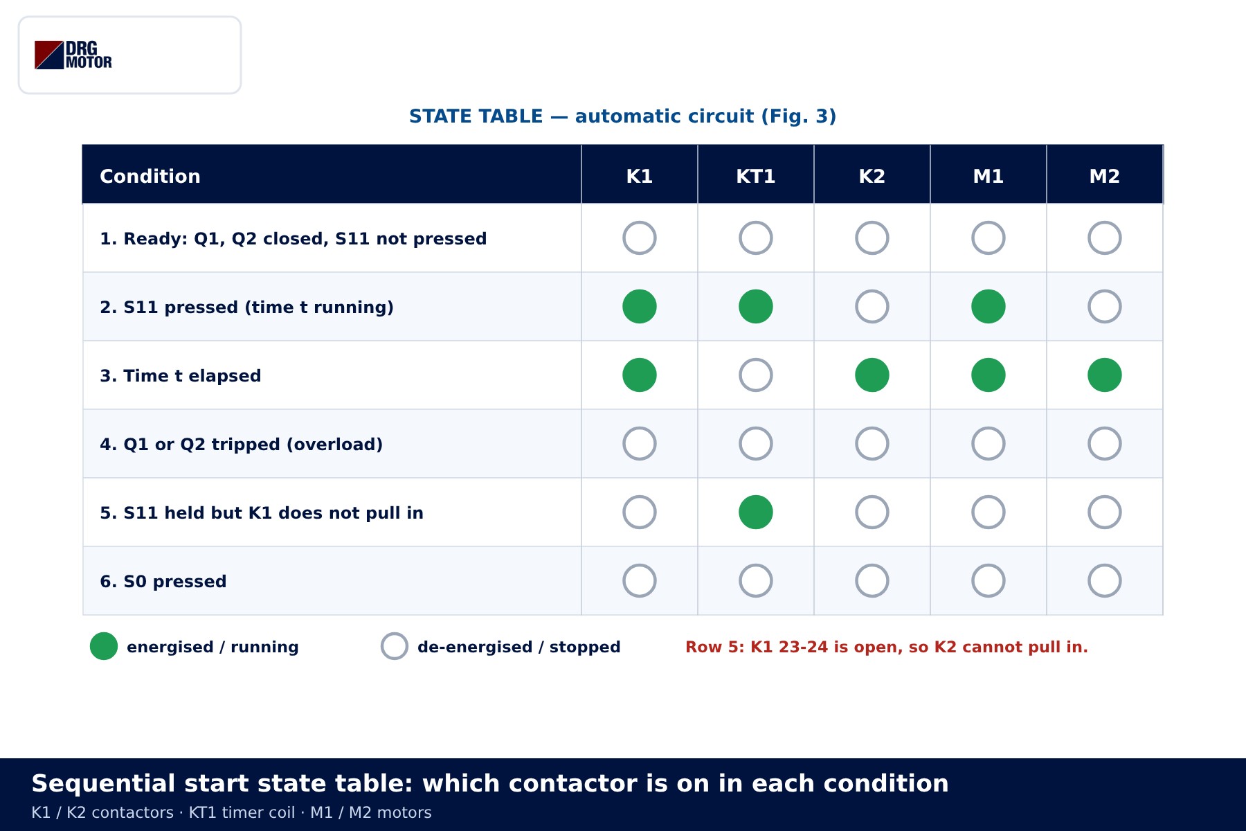
| Condition | K1 / M1 | K2 / M2 | Note |
|---|---|---|---|
| Ready, no start | Off | Off | Q1 and Q2 set, circuit waiting |
| S11 pressed, delay running | Running | Off | KT1 energised, M1 accelerating |
| Delay elapsed | Running | Running | KT1 de-energised, K2 latched |
| Q1 or Q2 tripped | Off | Off | Common series path open |
| S0 pressed | Off | Off | Restart needs S11 |
Conveyor line example: discharge belt first
On a two-belt line, belt B2 takes material from the hopper and drops it onto discharge belt B1, which carries it to the silo. Starting goes against the flow: the last belt in the flow (B1, M1) starts first, then the belt that feeds it (B2, M2). Stopping goes with the flow: the feed is cut first (M2 stops), and once B1 has emptied, M1 is stopped. In the manual circuit that means S21 first, then S0.
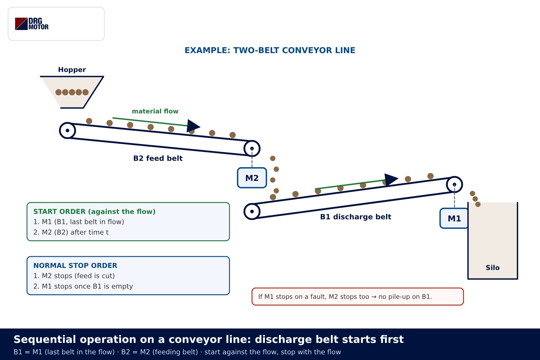
If M1 stops on a fault, the sequence condition also stops M2, so no material piles up on the stationary B1. With more than two belts the same logic is chained: each contactor coil branch gets a contact from the contactor of the belt that follows it in the flow. If a belt also has to run backwards, a forward-reverse contactor circuit is added.
Common wiring mistakes
| Symptom | Likely cause |
|---|---|
| M2 starts without M1 | K1 contact wired to NC terminals (21-22) or missing from the K2 branch |
| M2 keeps running after M1 stops | K1 23-24 placed only next to S22, outside the K2 self-holding path |
| M2 never starts | Missing K1 23-24 link, delay set far too long, or an NC terminal used instead of KT1 17-18 |
| K2 pulls in and drops at once | K2 13-14 self-holding contact not wired; the branch opens when KT1 releases |
| Both motors stop when Q2 trips | Normal in the automatic circuit (Q2 is in the common path); if unwanted, take Q2 13-14 into the K2 branch only |
Protection and motor selection
Q1 and Q2 are selected and set from each motor's nameplate current; motors of different power need different settings. Use the motor current chart for current values, the overload, fuse and contactor selection tool for device sizes and the motor cable size calculator for the supply cable. No single contactor size or cable cross-section fits every line; distance, ambient conditions and installation method change the result.
On conveyors M1 is often a little larger than M2, because the discharge belt carries its own load plus everything the feed belt delivers. Contactors, motor protection breakers, push buttons and timer relays are not sold by DRG; please contact your panel component supplier for those.
Frequently asked questions
Which K1 contact goes into the K2 branch?
A spare normally open auxiliary contact, usually 23-24 or 43-44. Since 13-14 is used for self-holding, a second NO contact is needed; if the contactor has none, an auxiliary contact block is added.
What if I want M1 to stop when M2 stops?
You cannot simply add a K2 NO contact to the K1 branch, because M1 would then never start. Instead, the Q2 13-14 contact is placed in the M1 series path, so an overload on M2 stops both motors. The automatic circuit already works this way.
How many seconds should the timer be set to?
There is no fixed value. The delay is set at commissioning so that M1 finishes its start, its current settles and the belt reaches conveying speed.
Can two motors be sequenced with one contactor?
No. A single contactor switches both motors at once and does not allow separate protection. Each motor needs its own contactor and its own protection.
Where does the emergency stop go?
An emergency stop should not be treated as just another stop contact in series. The safety function is designed according to the risk assessment.
Send a photo of your current motor nameplate and we will find the suitable DRG model together.Send on WhatsApp
DRG motors for sequenced conveyors and feeders
DRG Motor is an electric motor manufacturer, supplier and seller. Below are a few 1500 rpm three-phase IEC motors in the power range often used on belt conveyors and feeders. The full range is listed on the three-phase asynchronous electric motors page and in the online store.
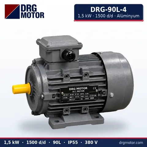
1.5 kW Three-Phase Motor 1500 rpm – DRG-90L-4 Aluminium
- 1.5 kW · 1500 rpm (4 poles)
- Aluminium frame · IEC 90L
- Mounting: B3 · B5 · B14 · B35
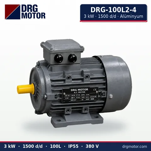
3 kW Three-Phase Motor 1500 rpm – DRG-100L2-4 Aluminium
- 3 kW · 1500 rpm (4 poles)
- Aluminium frame · IEC 100L
- Mounting: B3 · B5 · B14 · B35
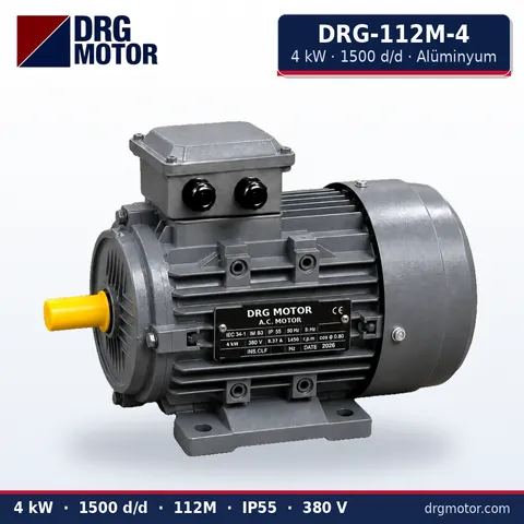
4 kW Three-Phase Motor 1500 rpm – DRG-112M-4 Aluminium
- 4 kW · 1500 rpm (4 poles)
- Aluminium frame · IEC 112M
- Mounting: B3 · B5 · B14 · B35
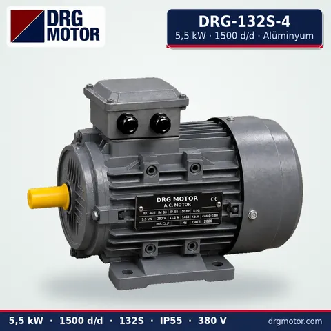
5.5 kW Three-Phase Motor 1500 rpm – DRG-132S-4 Aluminium
- 5.5 kW · 1500 rpm (4 poles)
- Aluminium frame · IEC 132S
- Mounting: B3 · B5 · B14 · B35
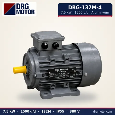
7.5 kW Three-Phase Motor 1500 rpm – DRG-132M-4 Aluminium
- 7.5 kW · 1500 rpm (4 poles)
- Aluminium frame · IEC 132M
- Mounting: B3 · B5 · B14 · B35
Click to see current prices for these motors and order nowSEE PRICES →
📄 Download Wiring Diagram PDF A4 printable PDF of the diagrams and tables (no sign-up)





