 English
 Le français
 Türkçe





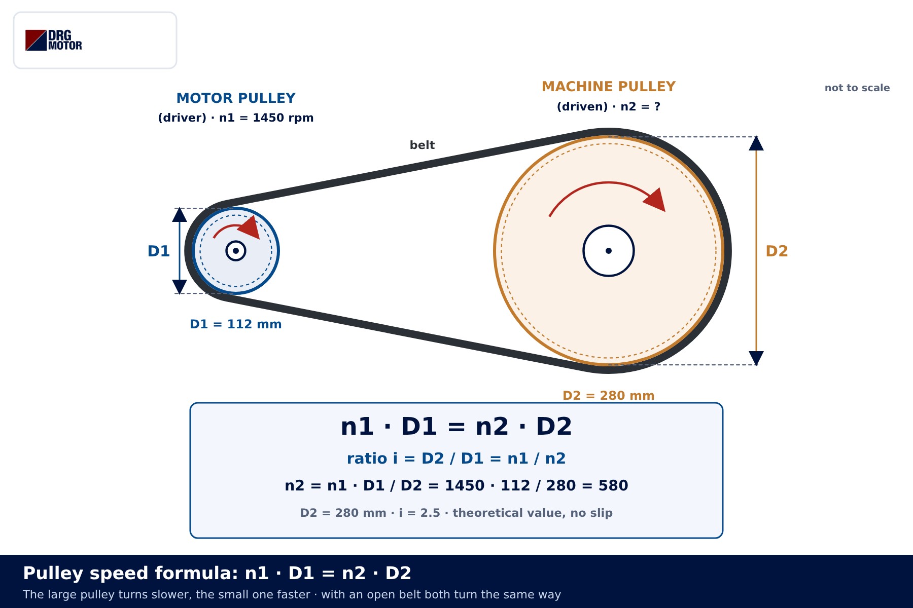
Pulley speed calculation rests on one equation: n1 · D1 = n2 · D2. Motor speed times motor pulley diameter equals machine speed times machine pulley diameter, so any one of the four values can be found from the other three. A motor running at 1450 rpm with a 112 mm motor pulley and a 280 mm machine pulley drives the machine at about 580 rpm.
Safety notice: This content is for technical information only. Wiring, measurement and commissioning must be carried out by qualified electrical personnel, following lock-out and verification of de-energised state, and in line with the motor and device manufacturer's documentation.
This article deals with the calculation only: the formula, which speed and which diameter to use, worked examples, two-stage drives, slip and torque. Selection topics such as motor power, shaft side load, bearings and belt tension are covered in Belt-Pulley Drive Motor Selection. For a quick check of your own numbers, use the pulley and belt calculator.
The pulley speed formula: n1 · D1 = n2 · D2
If the belt does not slip, every point on it travels at the same linear speed. On the motor pulley that speed is π · D1 · n1; on the machine pulley it is π · D2 · n2. Set the two equal, cancel π, and you are left with n1 · D1 = n2 · D2. The result matches intuition: the small pulley turns fast, the large one slowly. The drive ratio is written i = D2 / D1 = n1 / n2; with i above 1 the machine slows down, below 1 it speeds up.
| Symbol | Meaning | Unit |
|---|---|---|
| n1 | Motor (driver pulley) speed | rpm |
| D1 | Pitch diameter of the motor pulley | mm |
| n2 | Machine (driven pulley) speed | rpm |
| D2 | Pitch diameter of the machine pulley | mm |
| i | Drive ratio, D2 / D1 | none |
| z1, z2 | Tooth count of timing pulleys | teeth |
The formula is used in four forms: n2 = n1 · D1 / D2, D2 = n1 · D1 / n2, D1 = n2 · D2 / n1 and n1 = n2 · D2 / D1. As long as both diameters share one unit and both speeds share one unit, the answer is right; the ratio is dimensionless, so entering diameters in inches gives the same speed.
Which motor speed goes into the calculation?
The 1000, 1500 and 3000 rpm figures in a catalogue are synchronous speeds: the speed of the rotating field of a 6-, 4- or 2-pole motor on a 50 Hz supply. The rotor of an induction motor runs a little below that; the difference is the motor slip. For pulley calculations use the rated speed on the nameplate, not the synchronous figure. DRG three-phase induction motors come in the 1000, 1500 and 3000 rpm classes, and the rated speed of each model is shown on its nameplate and product page.
| Speed class (synchronous) | Poles | Typical nameplate speed |
|---|---|---|
| 3000 rpm | 2 | about 2800–2950 rpm |
| 1500 rpm | 4 | about 1380–1470 rpm |
| 1000 rpm | 6 | about 900–980 rpm |
These ranges are only a guide: small motors have more slip, large motors less. Calculate with 1500 and fit a motor rated at 1450, and the machine runs roughly 3 % slow. On 60 Hz the synchronous speeds become 1200, 1800 and 3600 rpm, and the nameplate value still rules. For power and current figures, the motor current chart and the electric motor calculator are useful.
Outside diameter or pitch diameter?
A V-belt pulley has three diameters you could measure: the outside diameter at the rim, the pitch (effective) diameter where the belt’s tension cords run, and the groove-bottom diameter. Belt speed equals the peripheral speed at the line of the tension cords, so the pitch diameter is the one that belongs in the formula. It is usually marked on the pulley or listed in the pulley catalogue.
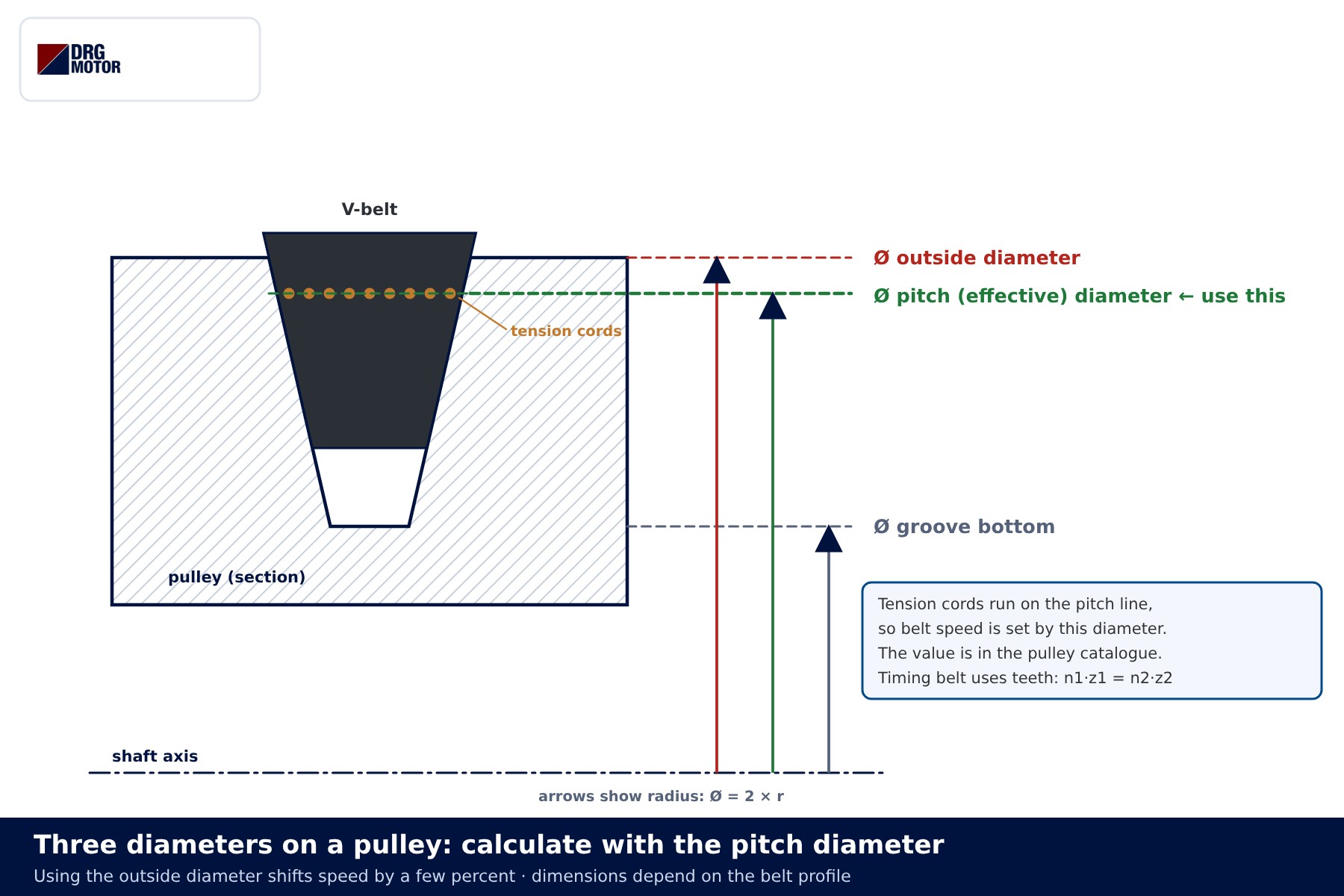
An outside-diameter calculation goes wrong most on small pulleys. The gap between outside and pitch diameter depends on the belt profile rather than on pulley size, so it is a roughly fixed amount; on a motor pulley of around 100 mm a few millimetres translate into a speed error of a few percent. Timing (toothed) belts use tooth counts instead of diameters: n1 · z1 = n2 · z2. Because a timing belt does not slip, that result is in practice what you will measure.
📄 Download Wiring Diagram PDF A4 printable PDF of the diagrams and tables (no sign-up)
Click to see current electric motor prices and order nowSEE PRICES →
Step-by-step calculation with examples
- Read the rated speed (n1) from the motor nameplate.
- Decide the machine speed (n2): the figure from the machine maker or the speed measured on the old setup.
- Find the ratio: i = n1 / n2.
- Choose the pitch diameter of one pulley; on the motor side, stay above the minimum diameter recommended for the belt profile.
- Calculate the other diameter and round it to the nearest standard pulley size.
- Recalculate the real speed with the rounded sizes and, allowing for slip, check it against the machine’s tolerance.
Example 1: machine speed from a 1450 rpm motor
Motor 1450 rpm, motor pulley 112 mm, machine pulley 280 mm. n2 = 1450 × 112 / 280 = 580 rpm, ratio i = 280 / 112 = 2.5. With a V-belt the measured speed will be a few rpm lower.
Example 2: machine pulley size from a target speed
A fan should run at 900 rpm; the motor turns at 1450 rpm and carries a 125 mm pulley. D2 = 1450 × 125 / 900 ≈ 201 mm. With a standard 200 mm pulley, n2 = 1450 × 125 / 200 ≈ 906 rpm. A gap of under one percent is acceptable for most fans.
Example 3: motor pulley when the machine pulley stays
The machine pulley is 250 mm and will not be changed; the target is 600 rpm. The motor is in the 1000 rpm class with a nameplate speed of 960 rpm. D1 = 600 × 250 / 960 ≈ 156 mm; the nearest 160 mm pulley gives n2 ≈ 614 rpm. Reaching the same target with a 1450 rpm motor would need D1 ≈ 103 mm. A small pulley bends the belt harder and raises belt force for the same power, so pulley size is part of choosing the motor speed class.
Calculation table
| Calculation | Known values | Formula | Result |
|---|---|---|---|
| Machine speed | n1 = 1450, D1 = 112, D2 = 280 | n2 = n1 · D1 / D2 | 580 rpm |
| Machine pulley | n1 = 1450, D1 = 125, n2 = 900 | D2 = n1 · D1 / n2 | ≈ 201 → 200 mm (≈ 906 rpm) |
| Motor pulley | n1 = 960, D2 = 250, n2 = 600 | D1 = n2 · D2 / n1 | ≈ 156 → 160 mm (≈ 614 rpm) |
| Ratio | D1 = 100, D2 = 315 | i = D2 / D1 | 3.15 |
| Two stages | n1 = 2900; 100/400 and 90/400 | n4 = n1 · (D1/D2) · (D3/D4) | ≈ 163 rpm |
| Belt speed | D1 = 112, n1 = 1450 | v = π · D1 · n1 / 60000 | ≈ 8.5 m/s |
All values are theoretical, without slip; diameters are pitch diameters in mm.
Two-stage pulley calculation
When one stage would need a very large ratio, either the big pulley no longer fits the machine or the wrap angle on the small pulley shrinks and the belt starts to slip. A countershaft solves this. Its two pulleys sit on the same shaft and turn at the same speed, and the overall ratio is the product of the stages: i = i1 · i2.
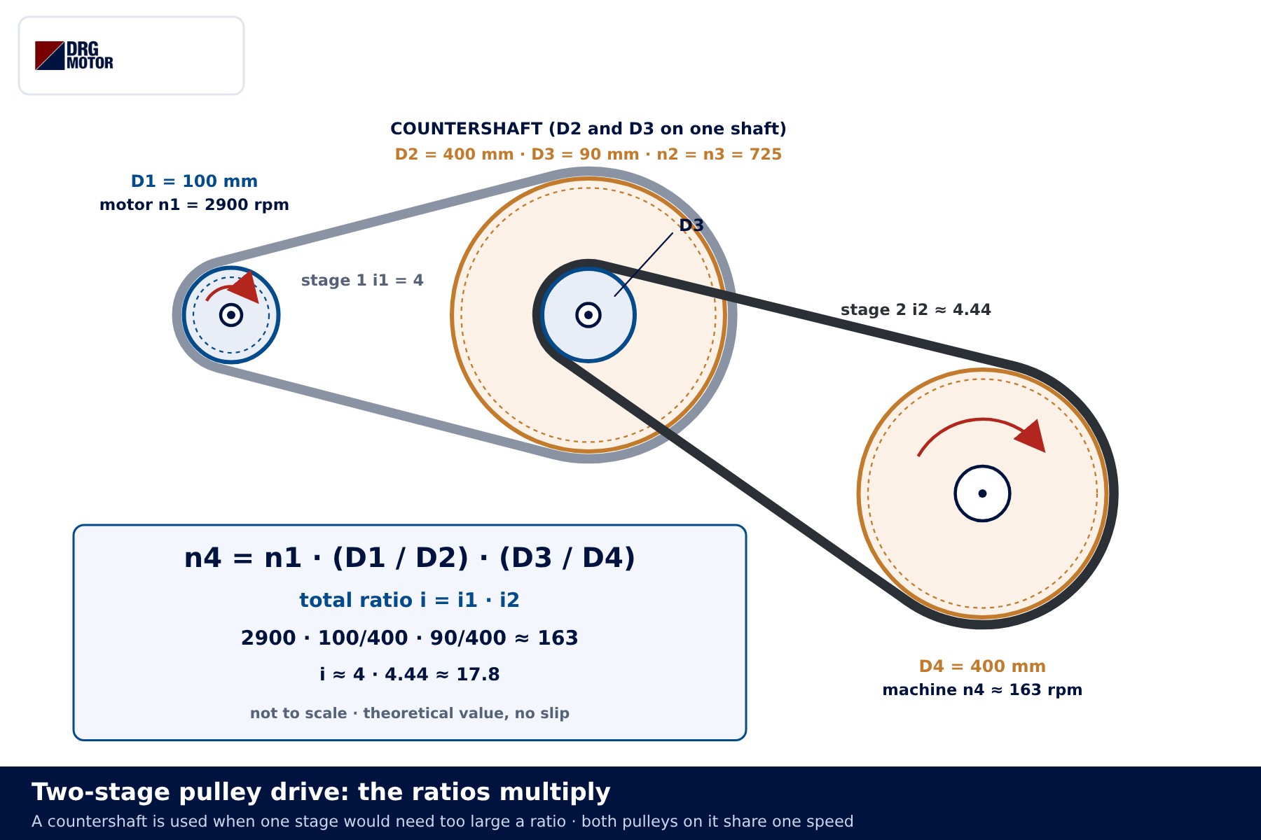
Example: a 2900 rpm motor, D1 = 100 mm, D2 = 400 mm, so the countershaft runs at 725 rpm. On the countershaft D3 = 90 mm, on the machine D4 = 400 mm: n4 = 725 × 90 / 400 ≈ 163 rpm. The overall ratio is 4 × 4.44 ≈ 17.8. Ratios multiply, they do not add; adding them is the classic two-stage mistake. Each stage slips on its own, so the total deviation is larger than with one stage. For very large ratios a gearbox can be more practical; gearboxes are not part of the DRG range and are selected from their manufacturer.
How much does belt slip change the speed?
The formula describes the no-slip case. Under load, a V-belt stretches more on the tight side than on the slack side, and this elastic creep makes the driven pulley turn a little below the theoretical speed. With a correctly tensioned belt of the right section the difference is usually small, typically within a few percent in most applications; the actual figure depends on belt type, load and tension. A loose belt is another matter: it really slips in the groove, heats up, squeals and loses speed as the load rises.
- If machine speed is critical, measure it with a tachometer after assembly and fine-tune a pulley diameter if needed.
- For work that needs speeds to stay in step (metering, dosing, timing), use a timing belt.
- Belt speed is v = π · D · n / 60000 (m/s); the permitted belt speed and the minimum pulley diameter come from the belt maker’s data.
Lower speed means higher torque: belt and pulley limits
A pulley does not create power; apart from losses, motor power reaches the machine unchanged. With power fixed, torque is inversely proportional to speed: T ≈ 9550 · P / n (T in Nm, P in kW, n in rpm). A 4 kW motor at 1450 rpm delivers about 26 Nm at its shaft; with i = 2.5 the machine shaft sees about 66 Nm.
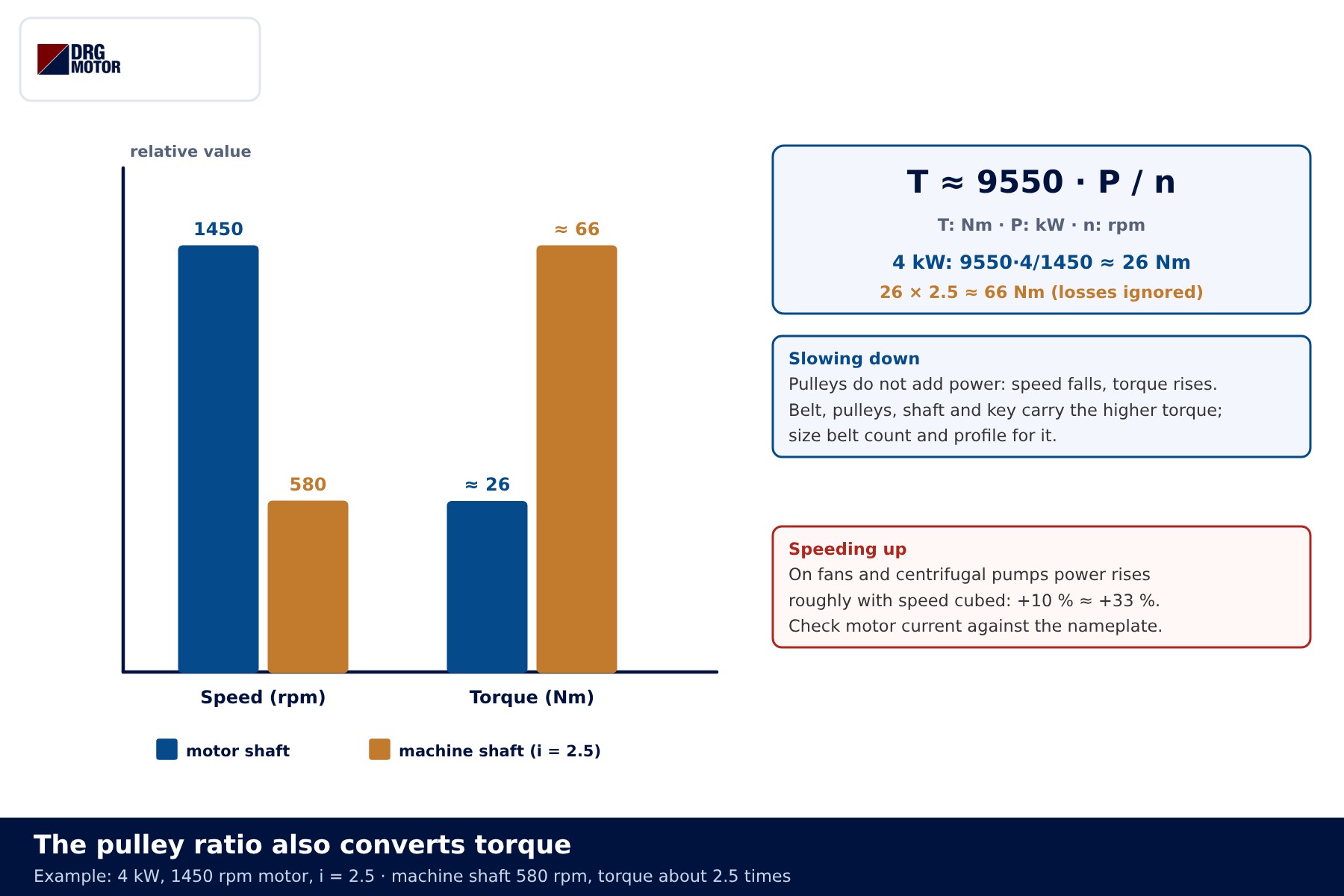
That higher torque loads the machine shaft, the pulley, the key and the belts. The number and profile of belts are chosen for the power and the small pulley diameter; a small motor pulley carries the same power with a higher belt force and puts more side load on the shaft and bearings. The opposite direction has its own trap: lowering the ratio to speed a machine up can overload the motor, because on fans and centrifugal pumps power demand rises roughly with the cube of speed, so 10 % more speed means about 33 % more power. After a pulley change, compare motor current with the nameplate current; if it has risen, expect overload trips. For large, heavy-starting drives, the article on star-delta connection covers one starting method.
Pulleys and belts are changed only with the machine de-energised and all rotating parts at a standstill; never run the drive without its belt guard refitted.
| Ratio | Machine speed | Machine torque | What to watch |
|---|---|---|---|
| i > 1 (D2 > D1) | lower | higher | belt count, key and shaft strength |
| i = 1 (D2 = D1) | same as motor | same as motor | only offsets the shaft axis |
| i < 1 (D2 < D1) | higher | lower | motor power, belt speed, machine speed limit |
Common calculation mistakes
| Symptom | Likely cause |
|---|---|
| Machine runs a few percent off the calculated speed | Outside diameter used instead of pitch diameter |
| Machine runs about 3–4 % slow | Calculated with the synchronous speed (1500) instead of the nameplate speed |
| Machine runs far faster than expected | Pulleys swapped; the ratio was applied the wrong way round |
| Two-stage result is far off | Ratios were added instead of multiplied, or the countershaft pulleys were mixed up |
| Speed drops under load, belt runs hot and squeals | Loose belt, too few belts or worn grooves |
| Motor current rose after speeding up | Fan or pump power demand climbed steeply with speed |
If an old pulley is reused on a replacement motor, compare shaft diameter and key size with the new motor. If the new motor’s rated speed differs from the old one, the machine speed changes by the same proportion, so redo the calculation with the new nameplate speed.
Send a photo of your current motor nameplate and we will find the suitable DRG model together.Send on WhatsApp
DRG motors for belt and pulley drives
DRG Motor is an electric motor manufacturer, supplier and seller. The three-phase IEC induction motors below cover the power range often used on belt-driven fans, compressors and machine tools; they come with IP55 protection, class F insulation and IC411 cooling. The 3 kW model is wound for 230/400 V, models from 4 kW upward for 400/690 V. Pulleys and belts are selected from the belt and pulley supplier’s catalogue. The full range is listed on the three-phase asynchronous electric motors page and in the online store.
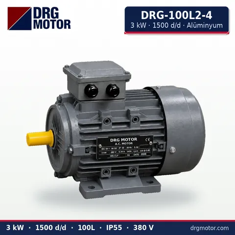
3 kW Three-Phase Motor 1500 rpm – DRG-100L2-4 Aluminium
- 3 kW · 1500 rpm (4 poles)
- Aluminium frame · IEC 100L
- Mounting: B3 · B5 · B14 · B35
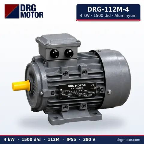
4 kW Three-Phase Motor 1500 rpm – DRG-112M-4 Aluminium
- 4 kW · 1500 rpm (4 poles)
- Aluminium frame · IEC 112M
- Mounting: B3 · B5 · B14 · B35
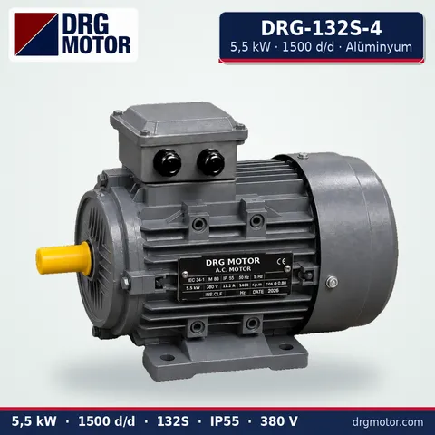
5.5 kW Three-Phase Motor 1500 rpm – DRG-132S-4 Aluminium
- 5.5 kW · 1500 rpm (4 poles)
- Aluminium frame · IEC 132S
- Mounting: B3 · B5 · B14 · B35
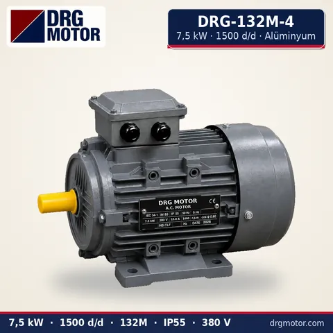
7.5 kW Three-Phase Motor 1500 rpm – DRG-132M-4 Aluminium
- 7.5 kW · 1500 rpm (4 poles)
- Aluminium frame · IEC 132M
- Mounting: B3 · B5 · B14 · B35
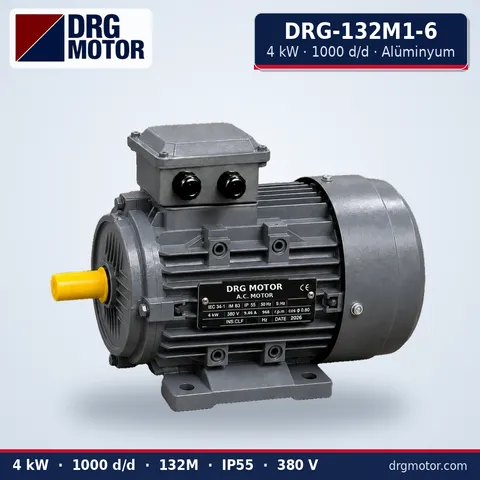
4 kW Three-Phase Motor 1000 rpm – DRG-132M1-6 Aluminium
- 4 kW · 1000 rpm (6 poles)
- Aluminium frame · IEC 132M
- Mounting: B3 · B5 · B14 · B35
Click to see current prices for these motors and order nowSEE PRICES →
Frequently asked questions
What ratio turns a machine at about 1000 rpm from a 1450 rpm motor?
i = 1450 / 1000 = 1.45. With a 100 mm motor pulley the machine pulley should be about 145 mm; a standard 150 mm pulley gives about 967 rpm.
Does the pulley ratio increase motor power?
No. Pulleys trade speed for torque; power only drops by the losses. Slowing down raises torque at the machine, speeding up lowers it.
Which pulley diameter should I measure?
Use the pitch (effective) diameter. It is marked on the pulley or given in its catalogue; if you only know the outside diameter, subtract the profile-specific difference from the catalogue.
Should I add a margin for belt slip?
Not if the speed is not critical. If it is, expect a result slightly below the theoretical value, measure after assembly or switch to a timing belt.
Try your own figures in the pulley and belt calculator, and keep all the drawings in one PDF:
📄 Download Wiring Diagram PDF A4 printable PDF of the diagrams and tables (no sign-up)





