English
 Le français
 Türkçe




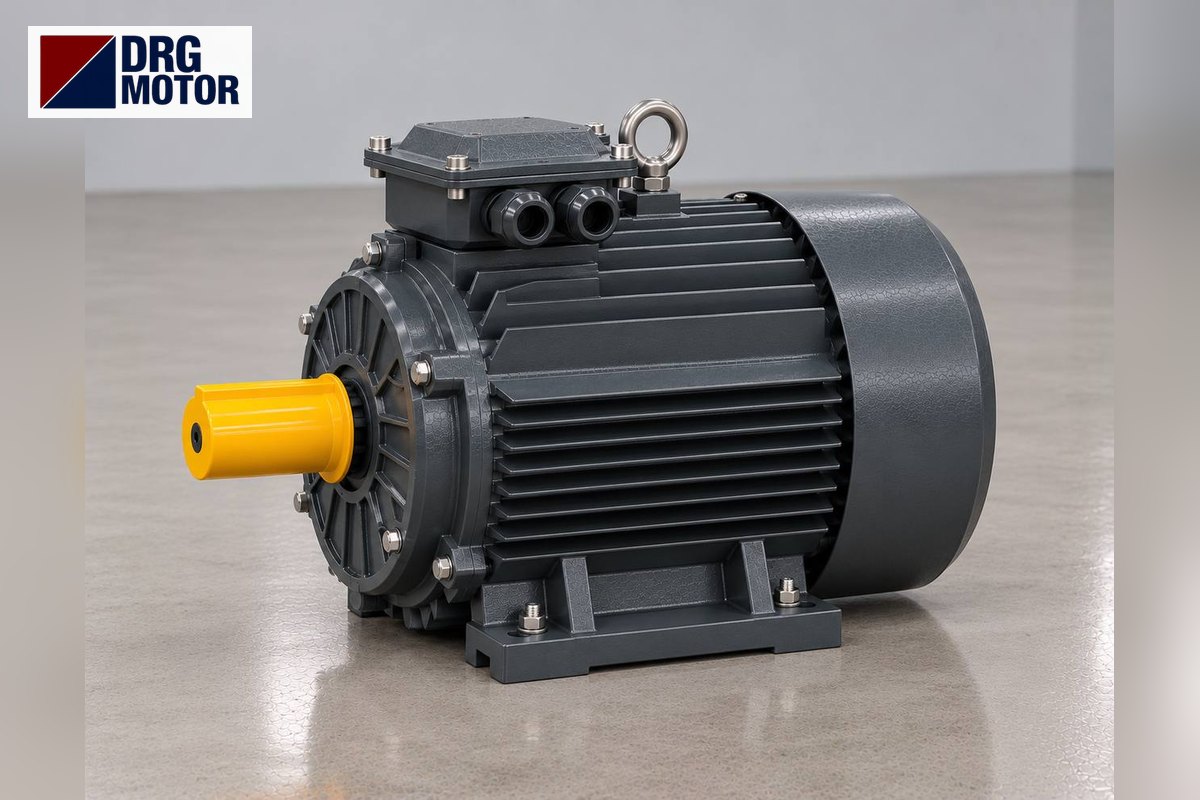

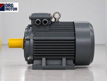
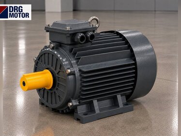
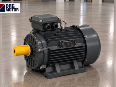
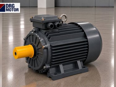
On a plastic film slitter rewinder, the main drive motor turns the draw roll that pulls the film through the knives at the set line speed and controls how the machine accelerates and decelerates. What decides the selection is not the steady load but the ability to reach full speed in a few seconds with a full mother roll and to stop precisely on the length counter. Four-pole three-phase motors on an inverter are used for this; power and housing options are listed in our online electric motor shop.
A slitter has more than one motor. The drives that unwind the mother roll, pull the film, turn the knives and wind the narrow reels are separate. This article centres on the main drive and also separates which of the others a standard motor can cover.
How Many Drives Does a Slitter Have?
The wide mother roll sits on the unwind shaft; the film passes over guide rolls to the roll pulled by the main drive. In the knife section, razor or shear-type circular knives cut the film into strips. The strips are wound into narrow reels on one or two rewind shafts, and the edge trim is pulled away by a fan.
| Drive | Function | Load type | Standard motor? |
|---|---|---|---|
| Main drive (draw roll) | Sets line speed | Acceleration, inertia | Yes, on inverter |
| Unwind | Brakes the mother roll | Regenerative braking | Mostly yes |
| Rewind shafts | Winds narrow reels | Tension, slipping | Depends on machine |
| Shear knife drive | Turns circular knives | Light, fixed speed | Yes |
| Edge trim fan | Pulls off edge trim | Fan load | Yes |
On most machines the unwind drive is an inverter-fed induction motor running regeneratively: it brakes the mother roll to create tension. The rewind side varies with machine design; we cover it separately below.
The Main Drive Carries Line Speed and Acceleration
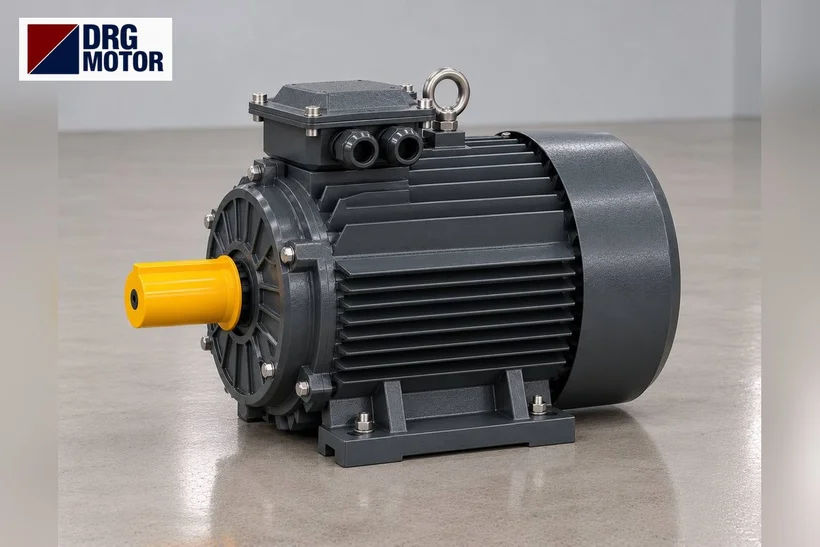
The main drive is the machine's speed reference; all other drives follow its speed. The film is clamped between the draw roll and a nip roll, so the roll's peripheral speed is the line speed.
Example / assumption: a 150 mm draw roll and 300 m/min line speed. From n = v / (π·D) the roll turns at about 637 rpm. With a 4-pole motor running at 1460 rpm this means a belt drive ratio of about 2.29. You can find the pulley diameters with our pulley and belt calculator.
The running load is small because film tension is balanced between unwind and rewind. The real load is accelerating the combined inertia of the mother roll, rolls and rewind reels on a short ramp. Since reel changes are frequent, the machine starts and stops dozens of times per shift.
Stopping and the braking resistor
When the set length is reached, the machine decelerates quickly. The energy of the rotating mass makes the motors act as generators and the inverter's DC bus voltage rises. This energy must be dissipated in the inverter's braking resistor; without one, or with one that is too small, the inverter trips on overvoltage. This is not a motor fault.
Click to see current electric motor prices and order nowSEE PRICES →
Rewind Side: Friction Shaft or Independent Drive?
On many machines the rewind shaft is a slipping (friction, differential) shaft. The shaft turns slightly faster than line speed and each narrow reel slips on its friction ring. Reels of different diameters are thus wound with the same tension. A single induction motor drives these shafts and torque is set with air pressure.
Example / assumption: 300 m/min line speed, 200 N total tension on the rewind, 76 mm cores and 400 mm full reels. If the shaft is run at about 1382 rpm, 1.1 times the reel speed at the core, the full reel needs 40 Nm on the shaft. From P = T·n/9550 power on the motor side is about 5.79 kW; only 1 kW of it goes into the film, the rest turns into heat in the slip rings.
This example explains why the motor of a friction shaft rewinder looks far larger than the film power. Do not downsize the old motor; overheating rings are a maintenance matter for the machine.
On rewinders with independent drives (each shaft centre wound by its own motor) and on very fast, high-precision machines, the rewind and unwind drives may be servo motors. A standard IEC motor cannot replace a servo motor; DRG's range has none. In that case DRG can only cover the induction motor parts such as the main drive, knife drive and fan.
Motor Dimensions and Connection: What to Check on Replacement
The main drive motor usually sits inside the machine side frame, foot mounted (B3) or B35, on slide rails with a belt connection. On replacement, measure the foot hole spacing, shaft height and pulley bore. On frame 100 the shaft is 28 mm and the foot holes 160×140 mm; on frame 132M the shaft is 38 mm and the foot holes 216×178 mm.
The inside of the side frame can be cramped and poorly ventilated; leave at least a hand's width in front of the fan cowl. Fine dust from the edge trim and film, attracted by static electricity, collects on the fan grille; regular cleaning keeps the motor cool at the same load.
Checklist before ordering or replacing
- Drive to be replaced: main draw, unwind, rewind shaft or knife
- Old nameplate: kW, rpm, voltage and connection
- Mounting (B3, B5, B35), foot hole spacing, shaft diameter and length
- Pulley or coupling connection, belt type
- Inverter present, maximum frequency and braking resistor
- Is the rewind or unwind motor a servo? If so, it cannot be replaced by a standard motor
Signs of a Wrong Choice on the Main Drive
If the inverter trips on overcurrent when starting with a full mother roll, either the ramp is too short or the motor power is not enough to accelerate the inertia. Lengthen the ramp first; if the fault remains, compare with the old nameplate. Overvoltage trips on stopping point to the braking resistor.
If the cut edges are wavy and line speed fluctuates during start-up, the speed match between main drive and rewind is off; this is usually a control setting. A motor fitted with the wrong number of poles changes the maximum line speed and shifts the counter settings.
DRG Motor is a manufacturer, supplier and seller of electric motors. We do not supply slitters, knife units, friction shafts or inverters; we supply the induction motors for these machines. All our models are also grouped on the three-phase asynchronous electric motors page.
DRG Motors Suited to Film Slitter Drives
The first three models cover the usual power range for main drives and friction shaft drives at 4-pole speed; the 0.75 kW model is for knives and small auxiliary drives.
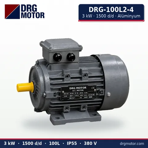
3 kW Three-Phase Motor 1500 rpm – DRG-100L2-4 Aluminium
- 3 kW · 1500 rpm (4 poles)
- Aluminium frame · IEC 100L
- Mounting: B3 · B5 · B14 · B35
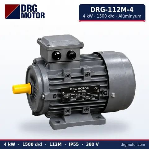
4 kW Three-Phase Motor 1500 rpm – DRG-112M-4 Aluminium
- 4 kW · 1500 rpm (4 poles)
- Aluminium frame · IEC 112M
- Mounting: B3 · B5 · B14 · B35
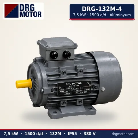
7.5 kW Three-Phase Motor 1500 rpm – DRG-132M-4 Aluminium
- 7.5 kW · 1500 rpm (4 poles)
- Aluminium frame · IEC 132M
- Mounting: B3 · B5 · B14 · B35
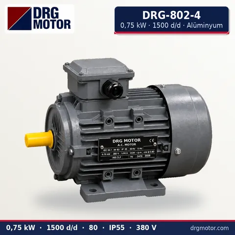
0.75 kW Three-Phase Motor 1500 rpm – DRG-802-4 Aluminium
- 0.75 kW · 1500 rpm (4 poles)
- Aluminium frame · IEC 80
- Mounting: B3 · B5 · B14 · B35
Click to see current prices and order these motors nowSEE PRICES →
Film Slitter Motor: Frequently Asked Questions
How many kW should a slitter rewinder main motor be?
Machine width, line speed and acceleration time decide; narrow, slow machines may use a few kW, wide and fast ones 15 kW and above. On replacement, go by the old nameplate; the exact value lies with the machine builder.
Why does the inverter trip on overvoltage when the slitter stops?
On a fast stop, the energy of the rotating reels returns to the inverter. Without a braking resistor, or with one that is too small, the DC bus voltage rises. The cure is a braking resistor on the inverter or a longer stop ramp.
Why is the motor of a friction shaft rewinder much larger than the film power?
The shaft turns faster than the reels and the difference becomes heat in the friction rings. The motor covers both the power going into the film and this slip loss.
Is the unwind motor harmed when it brakes?
No; regenerative operation is normal for an inverter-fed induction motor. The energy has to be dissipated in the inverter by a braking resistor or fed back to the grid.
To get a quote, send a photo of the label of the motor to be replaced, its power and speed, whether it is foot or flange mounted, the shaft size and which drive it runs on the machine via WhatsApp, or send the chosen models with the quote list. Phone: +90 (542) 666 11 11 · e-mail: info@drgmotor.com · contact page. Other powers and speeds are in our online shop.