 English
 Le français
 Türkçe





A forward-reverse motor control with limit switches is a contactor circuit that drives a carriage, gate or slide between two end points and stops the motor automatically at each end. Contactor K1 runs the motor forward and K2 runs it in reverse; the NC contact of limit switch B1 at the forward end opens the K1 rung, and B2 at the reverse end opens the K2 rung. Once an end is reached only the opposite-direction button works, so the carriage stops before it hits the end stop.
⚠ This content is for technical information only. Wiring, measurement and commissioning must be carried out by qualified electrical personnel, following lock-out and verification of de-energised state, and in line with the motor and device manufacturer's documentation.
The basic forward-reverse circuit (two contactors, holding contacts, interlock logic and motor selection) is covered in detail in our article on three-phase motor forward-reverse contactor wiring. This article focuses on how limit switches are added to that circuit, where they are connected and which wiring mistakes come up most often on site.
Power circuit: two contactors and phase reversal
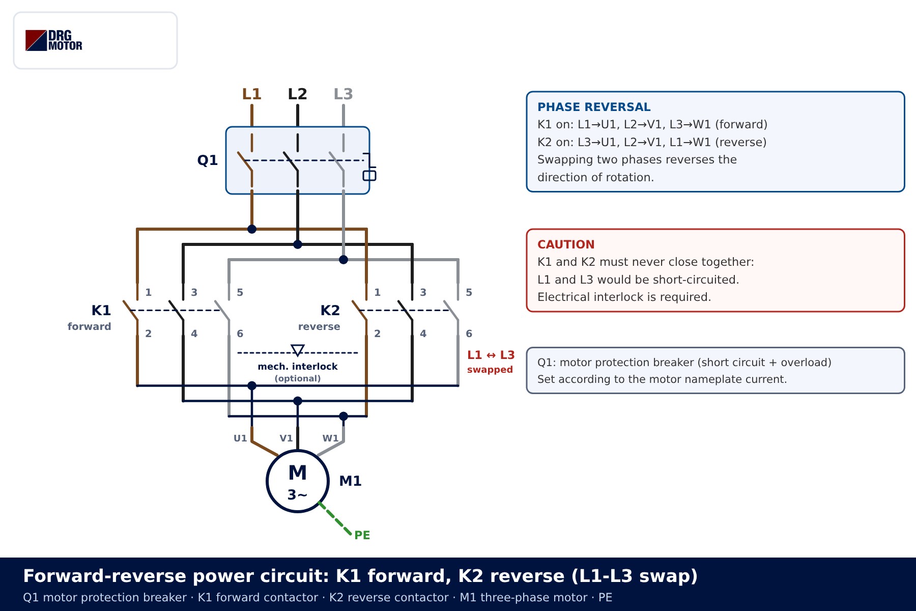
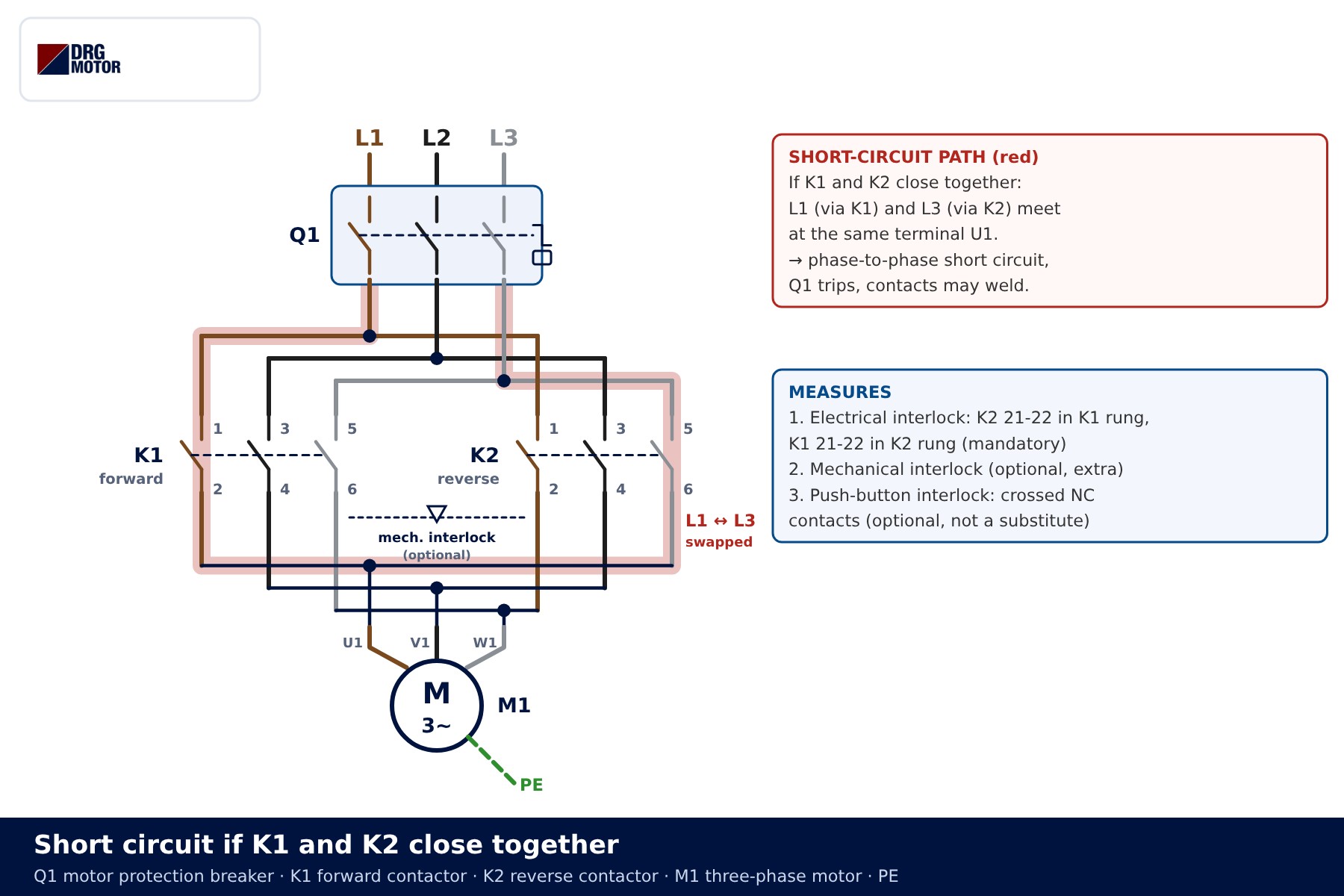
On the power side, the three phases coming from the Q1 motor protection breaker are split in parallel to two contactors. K1 feeds the motor in straight order (L1→U1, L2→V1, L3→W1). At the output of K2, L1 and L3 are swapped while L2 stays in the middle. Swapping two phases reverses the rotating field, so the motor turns the other way. The reasoning is explained in motor rotation direction reversing.
What happens if both contactors close together?
If K1 and K2 close at the same time, phase L1 (through K1) and phase L3 (through K2) arrive at the same terminal U1. That is a direct phase-to-phase short circuit: Q1 trips and the contactor contacts may burn or weld from the arc. A welded contact will cause trouble on the next start. This is why an electrical interlock in the control circuit is mandatory, while a mechanical interlock is an optional additional measure.
📄 Download Wiring Diagram PDF A4 printable PDF of the diagrams and tables (no sign-up)
Control circuit: where do the limit switches go?
The control circuit is drawn as a vertical ladder with the L rail at the top and the N rail at the bottom. The common line carries, in order, the F3 control fuse, auxiliary contact 13-14 of Q1, the S9 emergency stop and the S0 stop button. Two rungs branch off this line: forward (K1) on the left and reverse (K2) on the right. From top to bottom each rung contains:
- The direction button (NO, 13-14) with its own holding contact (K1 or K2, 13-14) in parallel.
- The end-position limit switch for that direction (B1 or B2, NC 21-22).
- The interlock contact of the opposite contactor (K2 or K1, NC 21-22).
- The contactor coil (A1-A2).
The key point: the limit switch is connected below the point where the holding contact rejoins the button branch. When B1 opens, current from both the button and the holding contact is cut and K1 drops out. If the limit switch is bridged by the holding contact, the carriage will run past the limit without stopping.
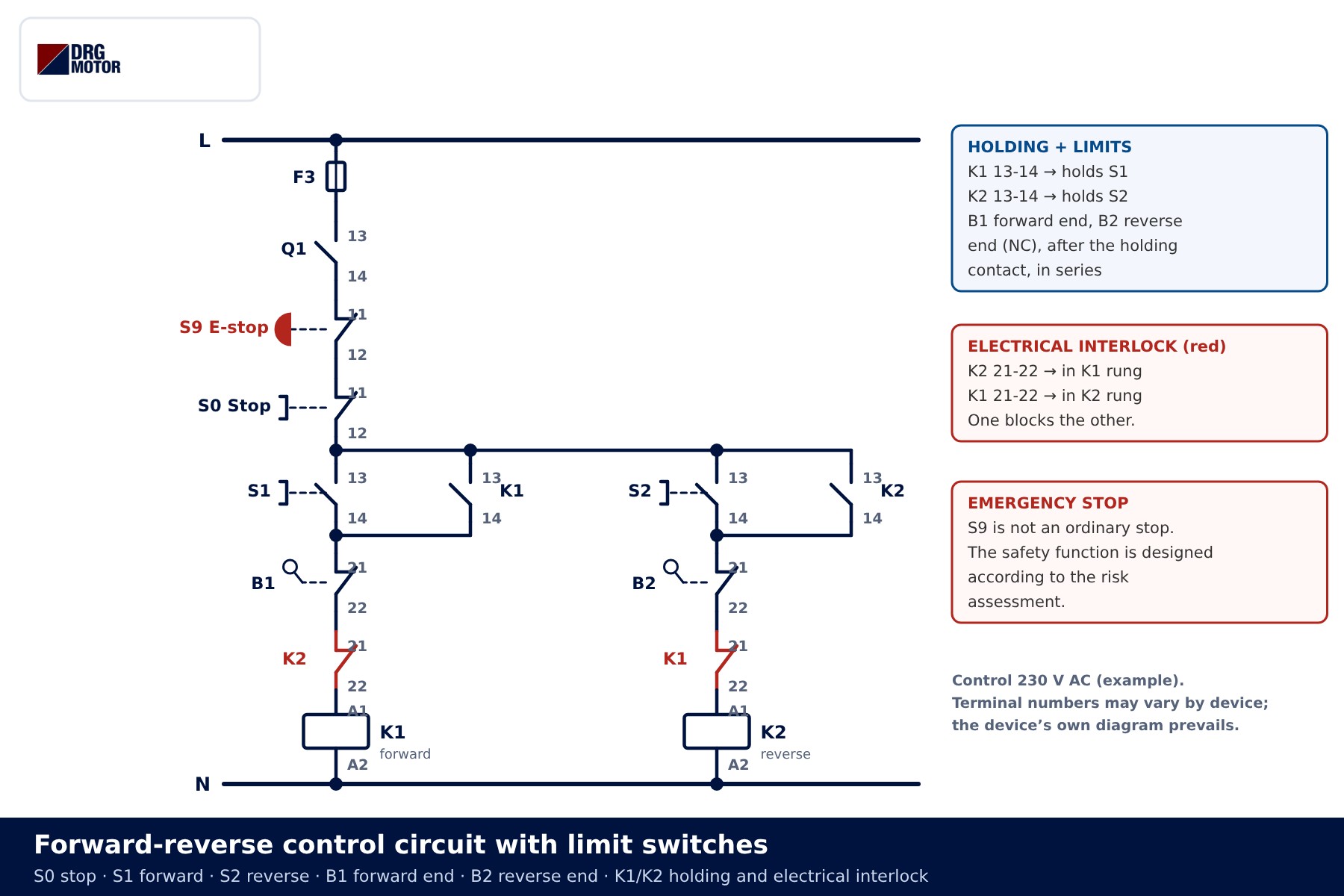
The S9 emergency stop is drawn as a separate device with its own symbol, not as an ordinary stop. Emergency stopping is a safety function; its category, number of channels and devices are designed according to the risk assessment. It is shown here only to indicate its position in the circuit. Terminal names vary by device; the device's own wiring diagram prevails.
Circuit components
| Code | Component | Contact | Function |
|---|---|---|---|
| Q1 | Motor protection breaker | 3 main + 13-14 NO | Short-circuit and overload protection; also cuts the control circuit when it trips |
| F3 | Control fuse | — | Protects the control circuit |
| S9 | Emergency stop | NC, latching | Safety function; designed according to the risk assessment |
| S0 | Stop button | NC 11-12 | Normal stop for both directions |
| Forward / reverse button | Direction buttons (forward and reverse) | NO 13-14 | Energise the corresponding contactor |
| K1 / K2 | Forward / reverse contactor | 13-14 NO, 21-22 NC | Holding and interlock of the other rung |
| B1 | Forward-end limit switch | NC 21-22 | Opens the K1 rung |
| B2 | Reverse-end limit switch | NC 21-22 | Opens the K2 rung |
A limit switch with a positive-opening NC contact is preferred: even if the contact sticks, the cam pressing the roller separates it mechanically. The NO contact (13-14) of the limit switch is not used to cut the direction in this circuit; if needed it is reserved for a pilot lamp or a PLC input.
Click to see current electric motor prices and order nowSEE PRICES →
Travel path and limit switch positioning
A cam (striker) fixed to the carriage presses the limit switch roller at the end of travel. B1 sits at the forward end, B2 at the reverse end. Behind each limit switch there is a mechanical end stop; in normal operation it should never be touched and remains only as a last resort.
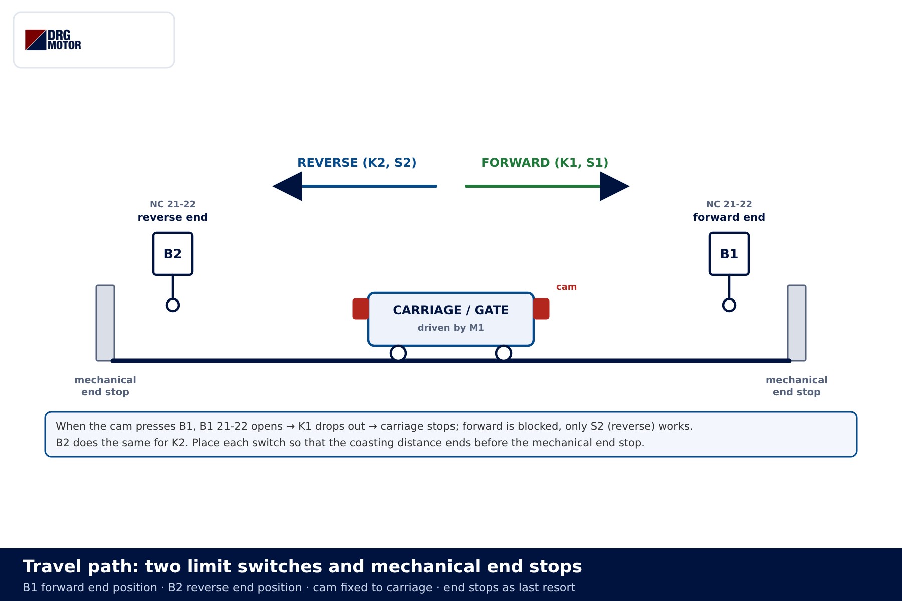
After the motor is switched off, the carriage coasts a little further. Each limit switch is positioned so that this stopping distance ends before the end stop. Heavier loads and higher speeds lengthen the stopping distance, so the setting is checked under load during commissioning. For heavy or fast movements, a brake or controlled deceleration with a drive should be considered as well.
Sequence of operation, step by step
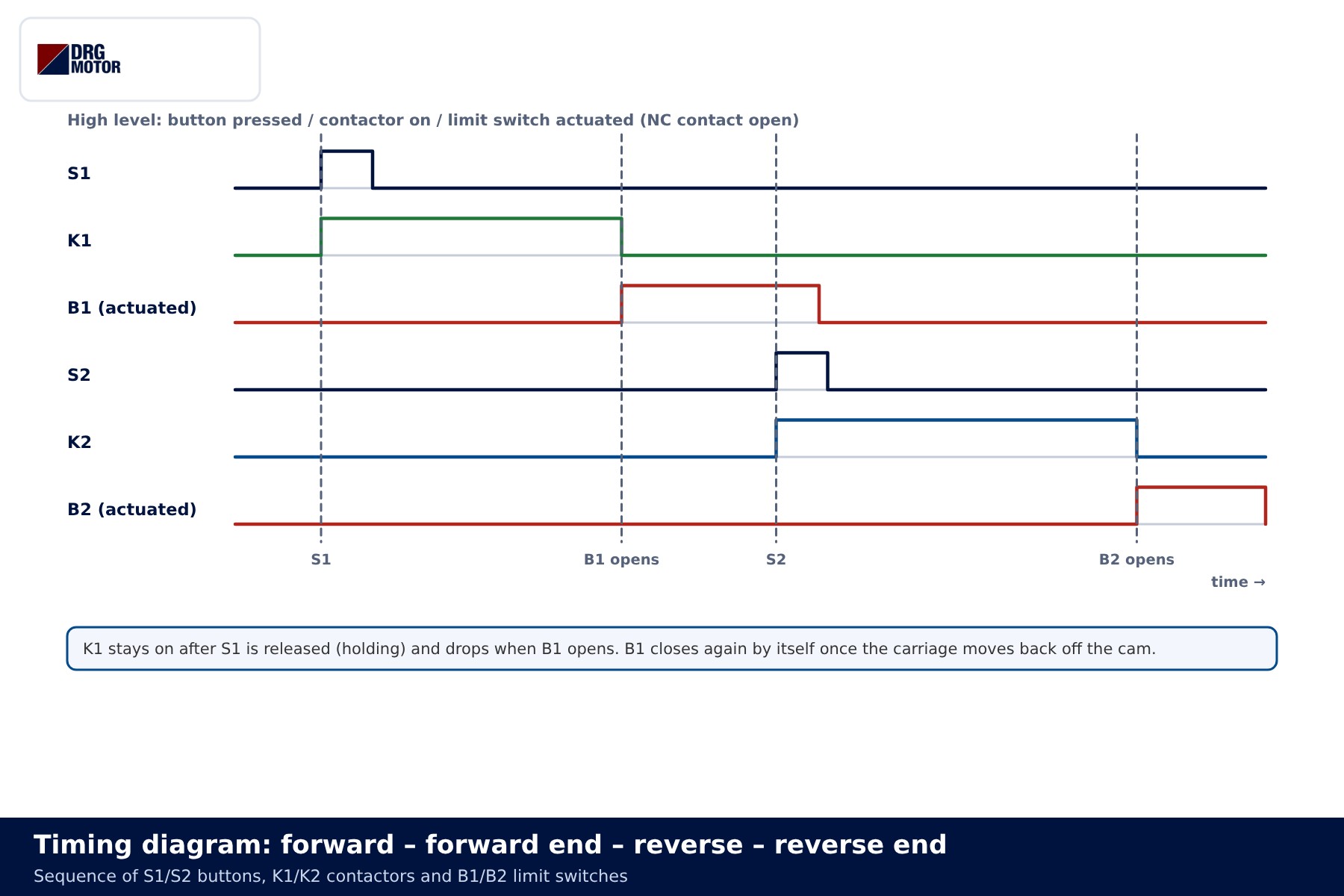
- Forward button pressed: current flows through S9, S0, the button, B1 (closed) and K2 21-22 (closed) to the K1 coil. K1 pulls in and the motor runs forward.
- Button released: K1 13-14 is closed, so the coil stays energised (holding). At the same time K1 21-22 opens and locks out the K2 rung.
- Reverse button pressed while K1 is on: nothing happens, because K1 21-22 has opened the K2 rung. To change direction, stop first with S0.
- Cam reaches B1: B1 21-22 opens, K1 drops out and the motor stops. K1 21-22 closes and the K2 rung is released.
- Forward button while B1 is actuated: B1 is open, so K1 cannot pull in; the carriage cannot go past the forward end.
- Reverse button pressed: K2 pulls in and the carriage moves back; once the cam leaves B1, B1 closes by itself.
- Cam reaches B2: K2 drops out and the carriage stops at the reverse end.
- S0, S9 or Q1 opens: whichever direction is running stops and the holding is released; the motor does not restart by itself when power returns.
State table
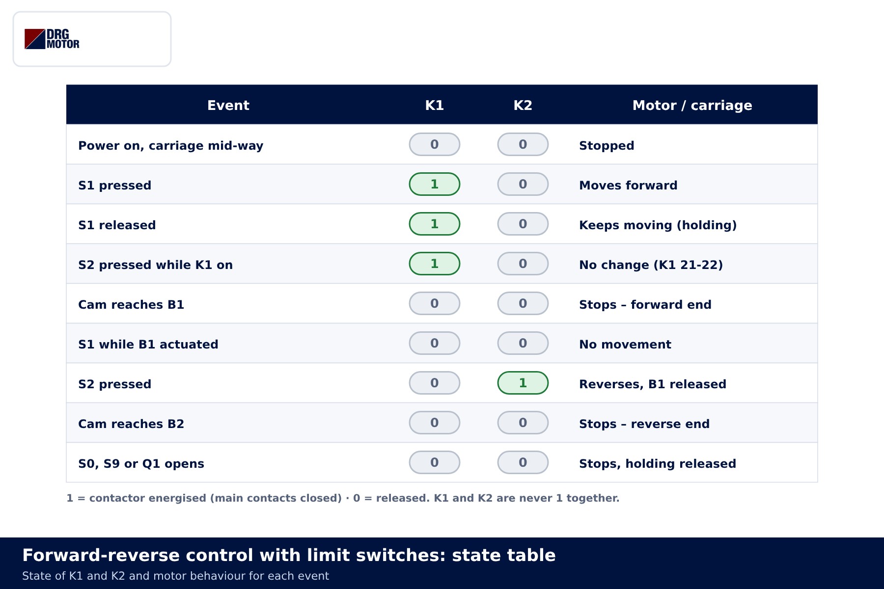
| Event | K1 | K2 | Result |
|---|---|---|---|
| Power on, carriage mid-way | 0 | 0 | Stopped |
| Forward button pressed | 1 | 0 | Moves forward |
| Forward button released | 1 | 0 | Keeps moving (holding) |
| Reverse button while K1 is on | 1 | 0 | No change (K1 21-22 interlock) |
| Cam reaches B1 | 0 | 0 | Stops at forward end |
| Forward button while B1 actuated | 0 | 0 | No movement |
| Reverse button pressed | 0 | 1 | Moves back, B1 released |
| Cam reaches B2 | 0 | 0 | Stops at reverse end |
| S0, S9 or Q1 opens | 0 | 0 | Stops, holding released |
No row shows K1 and K2 both at 1. Checking this is the quickest way to confirm the circuit is built correctly.
Is a mechanical or push-button interlock needed?
The electrical interlock (NC 21-22 contact of the opposite contactor) is essential in this circuit. A mechanical interlock fitted between the two contactors is optional: it physically prevents one from closing even if the other has a welded contact or a mechanically stuck armature. Cross-wiring the NC contacts of the direction buttons (push-button interlock) is also possible, but it does not replace the electrical interlock. Which measures are required is decided by the risk assessment of the application.
Reversing before the motor has stopped stresses both the mechanism and the contactors. In applications with frequent reversing, the contactor must suit that utilisation category; for sizing you can use the overload, fuse and contactor selection tool and the motor current chart.
Common wiring mistakes
| Symptom | Likely cause |
|---|---|
| Carriage does not stop at the limit | Limit switch bridged by the holding contact, or its NO contact (13-14) wired |
| Does not stop at forward end; forward button dead at reverse end | B1 and B2 swapped; forward limit wired into the K2 rung |
| Forward button moves the carriage backwards and it does not stop at the limit | Motor phase sequence reversed; carriage travels towards the other rung's limit |
| Q1 trips when changing direction | No interlock contact, or NO used instead of NC; reversing before the motor stops |
| Motor stops when the button is released | Holding contact wrong (NC used) or not in parallel with the button |
| No button works | F3 blown, S9 latched, Q1 13-14 open, or carriage at a limit and the wrong direction pressed |
The third row is particularly dangerous: if the motor is connected in the wrong phase order, the forward button drives the carriage towards B2, but B2 only sits in the K2 rung, so it does not stop K1 and the carriage hits the mechanical end stop. During commissioning, first run a short direction test well away from the limit switches, then press each limit switch by hand to confirm that the corresponding contactor drops out.
Application and motor selection examples
- Sliding yard gate or sliding panel: light loads with 0.75–1.5 kW, 1500 rpm motors and a gear transmission. Wind load and gate weight must be taken into account.
- Rail transfer cart or feed slide: motors of 1.5–3 kW are common; with a high number of starts, motor heating and cooling must be considered.
- Heavy transfer car: at 4 kW and above the stopping distance grows, so a brake or controlled deceleration is considered together with the limit switches.
On the protection side, we compared the Q1 motor protection breaker with a thermal relay in thermal relay vs motor protection breaker. For another application of holding-contact logic, see the star-delta control circuit.
Send a photo of your current motor nameplate and we will find the suitable DRG model together.Send on WhatsApp
DRG motors for forward-reverse applications with limit switches
DRG Motor is a manufacturer, supplier and seller of electric motors. The three-phase induction motors below have IP55 protection and class F insulation and can be used with a forward-reverse contactor circuit. Contactors, limit switches, push-buttons and motor protection breakers are not sold by DRG; please contact your panel component supplier for those. Other ratings and speeds are listed on the three-phase asynchronous electric motors page and in the online store.
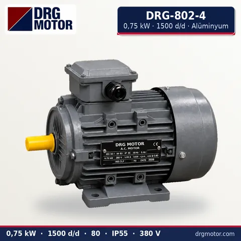
0.75 kW Three-Phase Motor 1500 rpm – DRG-802-4 Aluminium
- 0.75 kW · 1500 rpm (4 poles)
- Aluminium frame · IEC 80
- Mounting: B3 · B5 · B14 · B35
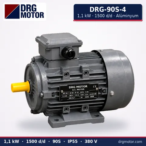
1.1 kW Three-Phase Motor 1500 rpm – DRG-90S-4 Aluminium
- 1.1 kW · 1500 rpm (4 poles)
- Aluminium frame · IEC 90S
- Mounting: B3 · B5 · B14 · B35
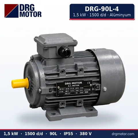
1.5 kW Three-Phase Motor 1500 rpm – DRG-90L-4 Aluminium
- 1.5 kW · 1500 rpm (4 poles)
- Aluminium frame · IEC 90L
- Mounting: B3 · B5 · B14 · B35
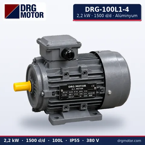
2.2 kW Three-Phase Motor 1500 rpm – DRG-100L1-4 Aluminium
- 2.2 kW · 1500 rpm (4 poles)
- Aluminium frame · IEC 100L
- Mounting: B3 · B5 · B14 · B35
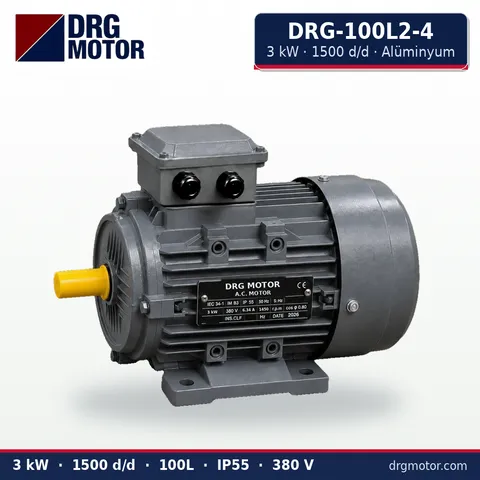
3 kW Three-Phase Motor 1500 rpm – DRG-100L2-4 Aluminium
- 3 kW · 1500 rpm (4 poles)
- Aluminium frame · IEC 100L
- Mounting: B3 · B5 · B14 · B35
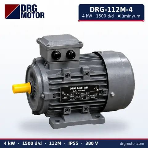
4 kW Three-Phase Motor 1500 rpm – DRG-112M-4 Aluminium
- 4 kW · 1500 rpm (4 poles)
- Aluminium frame · IEC 112M
- Mounting: B3 · B5 · B14 · B35
Click to see current prices for these motors and order nowSEE PRICES →
Frequently asked questions
Is the NO or the NC contact of the limit switch used?
The NC contact (21-22) is used, wired in series in the rung of the corresponding contactor. If a wire breaks or the contact opens, the motor also stops, so a fault ends on the safe side.
Why does the forward button not work while the carriage is at the limit?
That is the intended behaviour. As long as B1 is actuated the K1 rung is open; the carriage can only be moved away from the limit with the reverse button.
With an electrical interlock, is a mechanical interlock still needed?
The electrical interlock is mandatory. The mechanical interlock is an extra measure against contact welding or mechanical sticking and is added according to the risk assessment.
Is any further protection needed beyond the limit switch?
Each end should have a mechanical end stop. In higher-risk systems, a second overtravel switch that cuts the common control line can be placed slightly beyond each limit.
📄 Download Wiring Diagram PDF A4 printable PDF of the diagrams and tables (no sign-up)





