 English
 Le français
 Türkçe





When a motor contactor does not pull in, the fault is usually not in the contactor itself but in the control chain that feeds its A1-A2 coil: the control fuse, the overload relay's 95-96 contact, the stop button or a loose wire. If the contactor pulls in but chatters or buzzes, check first that the coil voltage matches the label and does not sag at pull-in, then look at the pole faces and the shading ring. The numbered test points and the symptom table below help you narrow the fault down in minutes.
⚠ This content is for technical information only. Wiring, measurement and commissioning must be carried out by qualified electrical personnel, following lock-out and verification of de-energised state, and in line with the motor and device manufacturer's documentation.
How a contactor pulls in: know the chain first
A contactor is an electromagnet: when its coil is energised, it pulls an iron armature and closes the main contacts (1-2, 3-4, 5-6). The coil voltage has to travel through a series chain from the top rail (L) down to the bottom rail (N). In a typical start-stop circuit the chain is: F3 control fuse → Q1 motor protection breaker auxiliary contact 13-14 → F2 overload relay NC contact 95-96 → S0 stop button (NC) → S2 start button (NO) with the K1 13-14 holding contact in parallel → K1 coil A1-A2.
If any element in this chain stays open, the coil gets no voltage and the contactor is completely silent. If the chain is complete but the coil voltage is low, or the magnet cannot close fully, the contactor pulls in but chatters. Telling these two cases apart is the first step of any diagnosis. For a detailed look at self-holding and interlocking logic, see the star-delta control circuit article.
| Device | Terminals | Function | Symptom when faulty |
|---|---|---|---|
| F3 control fuse | in / out | Protects the control circuit against short circuits | If blown, no contactor pulls in |
| Q1 motor protection breaker | 13-14 (NO) | Enables control only when Q1 is closed | No pull-in if Q1 is open or the contact is faulty |
| F2 overload relay | 95-96 (NC) | Opens the coil chain on overload | No pull-in when tripped; may trip again after reset |
| S0 stop / S2 start | 11-12 / 13-14 | Stop and start commands | Twitching on dirty contacts, no pull-in on a broken wire |
| K1 auxiliary contact | 13-14 (NO) | Self-holding: keeps the coil energised after Start is released | Pulls in while pressed, drops on release |
| K1 coil | A1-A2 | Pulls the armature in | Open coil: voltage present, no pull-in |
Numbered test points in the control circuit
In Figure 1 the rings (○) are test points and the solid dots (●) are electrical junctions. Keep one meter probe on the N rail (0 V) and move the other from point 1 to point 6. The first point where the voltage disappears lies right after the faulty element. For example, 230 V at point 3 but nothing at point 4 means F2 95-96 is open: the overload has tripped and not been reset, or the contact or wire is broken. To find out why the overload trips, follow the checks in why an electric motor trips the thermal overload.
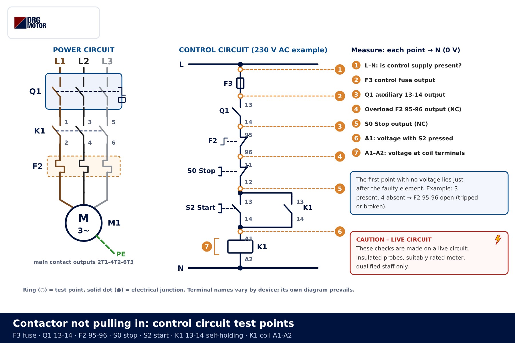
Live-work warning: measurements 1–7 are taken with the circuit energised. Use insulated probes, a meter with a measurement category suited to the installation and personal protective equipment; only qualified electrical staff should do this. Coil resistance, contact continuity and mechanical checks are made only after isolation and verification of the de-energised state.
Measurement sequence:
- 1 (L–N): no control supply means the problem is at the panel input or the control transformer.
- 2 (F3 output): voltage at 1 but not at 2 means the control fuse has blown. Before replacing it, look for a short in the coil or wiring.
- 3 (Q1 13-14): no voltage with Q1 closed points to the auxiliary contact or its wiring.
- 4 (F2 95-96): if the overload has tripped, reset it, but do not keep restarting the motor before finding the cause.
- 5 (S0 output): the stop button must be NC; if wired to the NO contact by mistake, the chain is always open.
- 6 (A1): voltage must appear while S2 is pressed. If not, the start button or its wire is faulty.
- 7 (A1–A2): measured directly across the coil. Voltage present but no pull-in means an open coil or a mechanically jammed armature.
If A1 shows voltage to N but there is none across A1–A2, the A2 return to the N rail is broken — an easily overlooked fault.
📄 Download Wiring Diagram PDF A4 printable PDF of the diagrams and tables (no sign-up)
Click to see current electric motor prices and order nowSEE PRICES →
Coil voltage mismatch: read the label
The contactor coil carries its voltage, current type and frequency (for example “Uc 230 V AC 50/60 Hz” or “24 V DC”). The control supply must match all three. Fitting a replacement contactor with a different coil after a breakdown is a common field mistake.
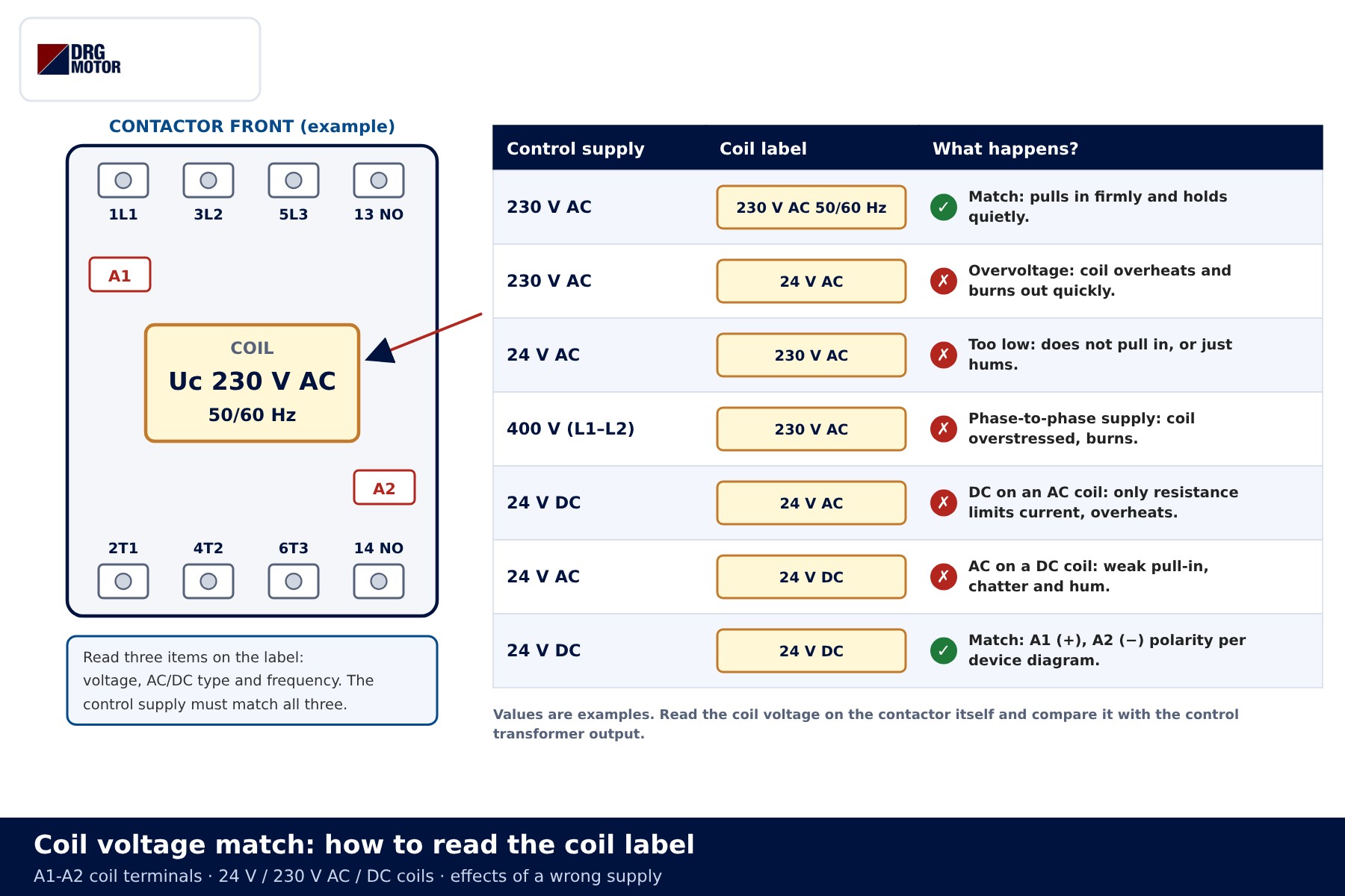
- Supply higher than the label (24 V AC coil on 230 V AC): the coil overheats and burns out quickly.
- Supply lower than the label (230 V AC coil on 24 V AC): the contactor does not pull in, or only hums.
- Phase-to-phase supply: a 230 V coil connected between L1 and L2 (400 V) is severely overstressed.
- DC on an AC coil: on AC, inductance limits most of the current; on DC only the winding resistance does, so the coil overheats.
- AC on a DC coil: the pull-in force is weak and the contactor chatters and hums. On DC coils, watch A1 (+) and A2 (−) polarity, especially with a built-in diode or an electronic coil.
If the label does not say 50/60 Hz, check the frequency as well. For contactor size and coil selection, see how to choose a contactor for a motor panel.
Why does a contactor chatter?
In an AC coil, the magnetic flux passes through zero every half cycle. At those instants the holding force also drops to zero, the spring pushes the armature back and chatter starts. The part that prevents this is the copper shading ring embedded in the pole face of the fixed core: the current induced in the ring produces a second, phase-shifted flux that keeps the holding force from reaching zero.
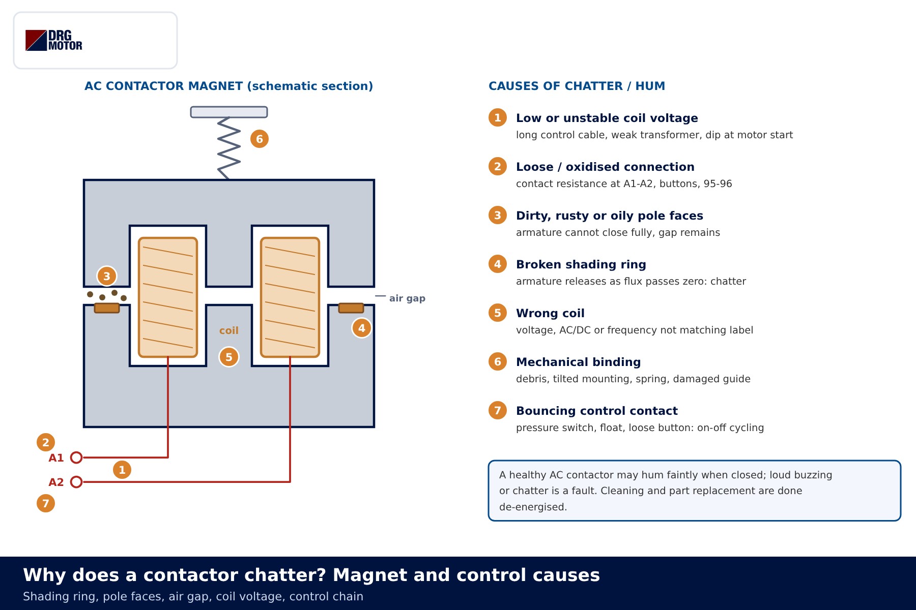
The main causes of chatter:
- Low or unstable coil voltage: an AC coil draws several times its holding current at pull-in. A weak control transformer or a long, thin control cable makes the voltage sag at that moment.
- Loose or oxidised connection: contact resistance at A1-A2, at a button or at 95-96 drops voltage and heats up.
- Dirty, rusty or oily pole faces: the armature cannot close fully, an air gap remains, the coil current stays high and the coil heats up.
- Broken shading ring: causes a loud, harsh rattle. The ring cannot be repaired; the contactor or magnet assembly is replaced.
- Wrong coil: voltage, AC/DC type or frequency does not match the label.
- Mechanical binding: debris, tilted mounting, a fatigued spring or a damaged guide.
- Bouncing control contact: a pressure switch, float switch or loose button can switch the coil on and off several times a second.
A healthy AC contactor may hum faintly when closed; loud buzzing or rattling is a fault. Cleaning and part replacement are always done with the circuit isolated.
Symptom → check → possible cause table
The drawing and table below summarise the eight most common field situations. Checks marked ⚡ are made on a live circuit.
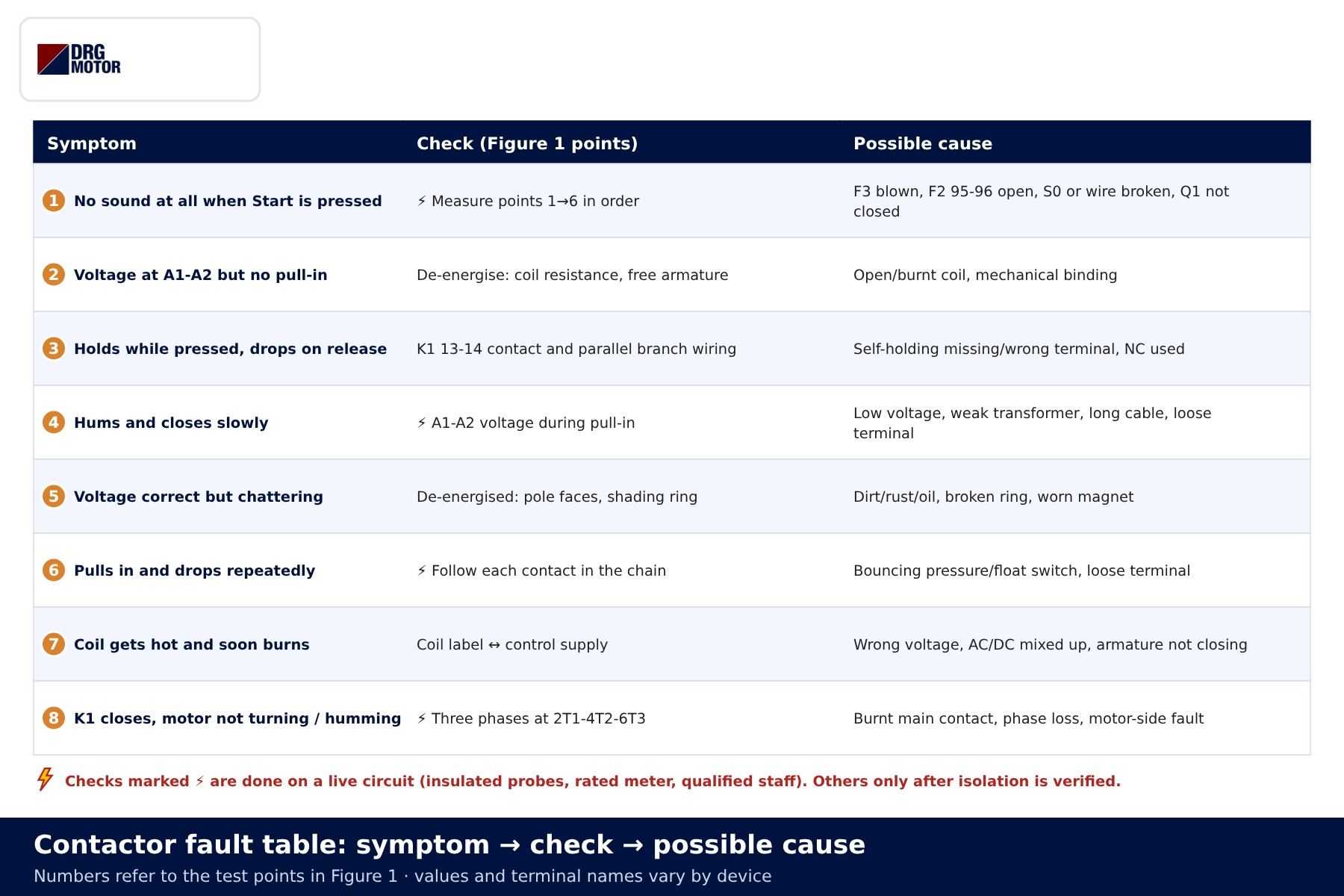
| Symptom | Check | Possible cause |
|---|---|---|
| No sound at all when Start is pressed | ⚡ Measure points 1→6 in order | F3 blown, F2 95-96 open, S0 or wire broken |
| Voltage at A1-A2 but no pull-in | Isolate; measure coil resistance | Open or burnt coil, armature jammed |
| Holds while pressed, drops on release | K1 13-14 and parallel branch wiring | Self-holding missing, wrong terminal or NC contact |
| Hums and closes slowly | ⚡ A1-A2 voltage during pull-in | Low voltage, weak transformer, long cable |
| Voltage correct but chattering | De-energised: pole faces and shading ring | Dirt, rust, broken shading ring |
| Pulls in and drops repeatedly | ⚡ Follow each contact in the chain | Bouncing pressure or float switch, loose terminal |
| Coil gets hot and soon burns out | Coil label ↔ control supply | Wrong voltage, AC/DC mixed up |
| K1 closes, motor not turning or humming | ⚡ Three phases at 2T1-4T2-6T3 | Burnt main contact, phase loss, motor fault |
In the last case the problem is no longer in the control circuit but in the power circuit: if a worn main contact fails to pass one phase, the motor runs on two phases. The risks are covered in why phase loss is dangerous for an electric motor.
Step-by-step troubleshooting flowchart
The flowchart starts with one question — “Does K1 pull in?” — and splits into three branches: no pull-in, drops on release, pulls in but chatters. In each branch the most likely and easiest check comes first; replacing parts is the last step.
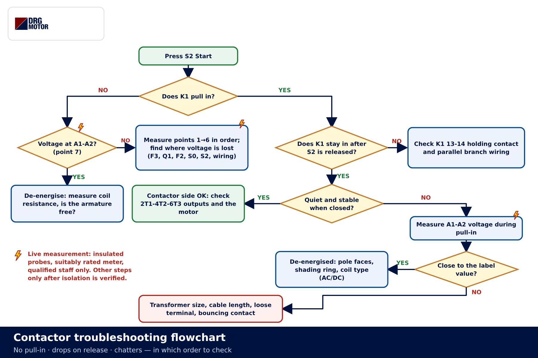
If the contactor stays in quietly and steadily but the motor still does not turn, check for three phases at the main contact outputs. If all three are present, move on to the motor; winding and insulation checks are a separate subject.
Common wiring mistakes
- Stop button wired to its NO contact: the contactor never pulls in, or pulls in when Stop is pressed.
- K1's NC contact (21-22) used for self-holding: drops on release or never holds.
- Overload contact 97-98 (NO) wired into the chain instead of 95-96: the circuit stays open unless the overload trips.
- A2 connected to another phase instead of N: the coil sees overvoltage.
- Control transformer too small for the total pull-in power of the coils: when several contactors close together, they all chatter.
You can pre-check overload and fuse values with the motor overload, fuse and contactor selection tool; the final setting follows the rated current on the motor nameplate and the device manufacturer's data.
Send a photo of your current motor nameplate and we will find the suitable DRG model together.Send on WhatsApp
If the motor needs replacing after a contactor fault: suitable DRG motors
A contactor that chatters for a long time, or a burnt main contact, can leave the motor on two phases and damage the winding. If the motor has to be replaced: DRG Motor is an electric motor manufacturer, supplier and seller, and the three-phase models below are in a power range common in panel applications. Contactors, overload relays, buttons and control transformers are not sold by DRG; please contact your panel component supplier for those. All options are listed on the three-phase asynchronous electric motors page and in the online store.
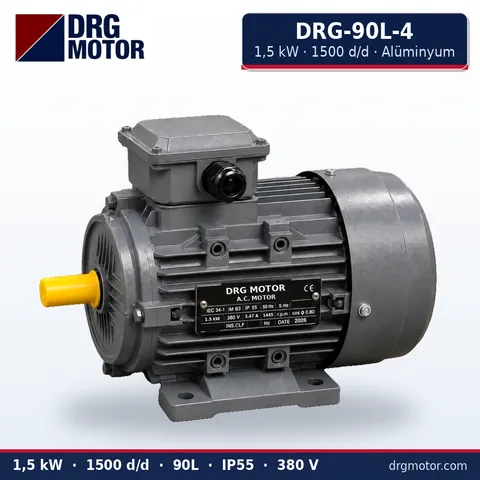
1.5 kW Three-Phase Motor 1500 rpm – DRG-90L-4 Aluminium
- 1.5 kW · 1500 rpm (4 poles)
- Aluminium frame · IEC 90L
- Mounting: B3 · B5 · B14 · B35
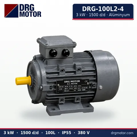
3 kW Three-Phase Motor 1500 rpm – DRG-100L2-4 Aluminium
- 3 kW · 1500 rpm (4 poles)
- Aluminium frame · IEC 100L
- Mounting: B3 · B5 · B14 · B35
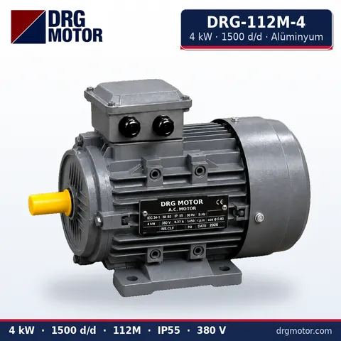
4 kW Three-Phase Motor 1500 rpm – DRG-112M-4 Aluminium
- 4 kW · 1500 rpm (4 poles)
- Aluminium frame · IEC 112M
- Mounting: B3 · B5 · B14 · B35
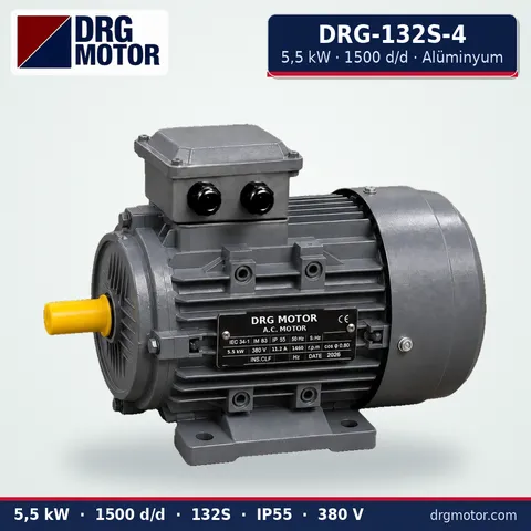
5.5 kW Three-Phase Motor 1500 rpm – DRG-132S-4 Aluminium
- 5.5 kW · 1500 rpm (4 poles)
- Aluminium frame · IEC 132S
- Mounting: B3 · B5 · B14 · B35
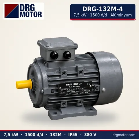
7.5 kW Three-Phase Motor 1500 rpm – DRG-132M-4 Aluminium
- 7.5 kW · 1500 rpm (4 poles)
- Aluminium frame · IEC 132M
- Mounting: B3 · B5 · B14 · B35
Click to see current prices of these motors and order nowSEE PRICES →
Frequently asked questions
Why does a contactor pull in and then drop out immediately?
The most common reason is a missing or miswired self-holding branch: K1's 13-14 NO contact must be in parallel with the start button. If that is correct, a voltage dip at pull-in or a loose terminal in the chain gives the same symptom.
Can contactor chatter damage the motor?
Yes. The main contacts of a chattering contactor open and close repeatedly, arc, wear and may lose a phase. The motor can then run on two phases and overheat. The coil also burns out quickly.
What happens if I connect a 24 V coil contactor to 230 V?
The coil sees far more than its rated voltage, draws excessive current and burns out within a short time. When replacing a contactor, always compare the coil label with the control supply.
How can I tell if the shading ring is broken?
If there is a harsh rattle even though the voltage is correct and the pole faces are clean, suspect the ring. After isolating and verifying the de-energised state, open the contactor and look for a crack or break in the copper ring on the core face. The ring is not repaired; the part is replaced.
📄 Download Wiring Diagram PDF A4 printable PDF of the diagrams and tables (no sign-up)





