English
 Le français
 Türkçe




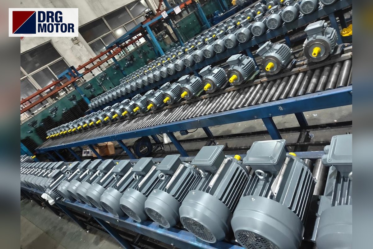

A metal chip conveyor motor is a low-power motor that drives the belt or auger under a machine tool at a very slow speed, often just a few metres per minute; its real job is not speed but stopping safely when a chip nest jams, without tearing the belt. That is why the decisive factors in a replacement are not kilowatts but the gearbox connection dimensions, the motor speed and the protection chain that reacts to a jam. On most CNC lathe and machining centre conveyors, a 4-pole motor in the 0.25–0.75 kW range is coupled to a worm gearbox; the exact value is on the conveyor manufacturer's rating plate.
This article covers load behaviour by conveyor type, jam and reverse logic, the dimensions to measure when matching a motor to the gearbox, and the common mistakes. If you have the nameplate data, you can find the equivalent by model code in the DRG online electric motor store.
Hinged Belt, Scraper and Auger: What Load Does the Motor See?
The three common types of chip conveyor load the motor differently. In all of them the motor sits behind a gearbox; what changes is how resistance builds up at the output shaft.
- Hinged steel belt: Perforated steel plates are linked to a chain and climb out of the coolant tank. They carry the long, curly chips of steel and stainless steel. The load comes less from weight than from chip nests catching on the cover or channel edge.
- Scraper type: Scraper bars on a chain push short chips and cast iron fines along the tank bottom. Sludgy chips settling at the bottom raise the load at start-up.
- Auger: A screw turning in a channel in the machine bed pushes chips to the collection point. If long chips wrap around the screw, torque rises within seconds.
What they share is a constant-torque load at a very low output speed. Speed is not increased; torque comes from the gearbox.
What Happens During a Jam: Torque Limiter, Overload Relay and Reversing
When the conveyor jams, the motor does not stop at once; its current rises first. The high gearbox ratio turns the motor's small torque into a very large force at the sprocket. Without protection, the weak link is not the motor but the belt pin, a chain link or the gearbox output shaft.
Well-designed conveyors therefore have three layers:
- Mechanical torque limiter (slip clutch): Fitted between the sprocket and the gearbox output shaft and set by spring pressure. It slips during a jam and saves the belt.
- Overload relay: Because motor current is small, the setting must be precise. A 0.25 kW motor draws only 0.66 A at 400 V; an overload set to 1 A will not protect it. Use the overload, fuse and contactor selection tool for the setting.
- Reverse operation: Many machine control programs have a conveyor forward/reverse command. Contactors swap two phases, the belt runs back briefly and releases the nest. A three-phase induction motor handles this reversal well; waiting for the motor to stop before reversing protects the gear teeth.
If the overload trips often, check the mechanics first. A dry chain, a worn sprocket, chip sludge filling the tank or a slack belt raise current long before the motor fails.
Click to see current electric motor prices and order nowSEE PRICES →
Worked Example: From Belt Speed to Gearbox Ratio
The values below are an example; a real conveyor may have a different sprocket diameter and speed.
Assumption: The hinged belt moves at 2 m/min and the sprocket pitch diameter is 160 mm. Sprocket speed is n = v / (π·D) = 2 / (π·0.16) ≈ 3.98 rpm. The DRG-711-4 motor has a rated speed of 1340 rpm, so the total reduction is about 337. This is typically a 1:50 worm gearbox combined with a chain stage of about 1:6.7.
The motor's rated torque is 1.78 Nm. Assuming a factor of 0.55 to cover gearbox and chain losses, torque at the sprocket shaft is 9550·0.25/3.98·0.55 ≈ 330 Nm and the belt pull is about 4.1 kN. This force shows clearly why a torque limiter is essential in a jam. You can also check your own gearbox output speed and torque with the matching logic on the electric motors for worm gearboxes page.
What to Measure When Matching a Motor to the Gearbox
On a chip conveyor the motor almost always mounts to the gearbox by flange. If the gearbox stays, the new motor's flange, shaft and key must match it exactly. Small worm gearboxes often use B14 (small flange); B14 dimensions are confirmed at order. For B5 large-flange frames, the DRG catalogue dimensions are:
| Frame | Shaft dia. × length (mm) | Flange OD / bolt circle (mm) | Spigot diameter (mm) |
|---|---|---|---|
| 71 (0.25–0.37 kW, 4-pole) | 14 × 30 | 160 / 130 | 110 |
| 80 (0.55–0.75 kW, 4-pole) | 19 × 40 | 200 / 165 | 130 |
The step in the table matters: going from 0.37 kW to 0.55 kW moves the frame from 71 to 80 and the shaft from 14 mm to 19 mm. So a "one size up" decision may also require changing the gearbox input sleeve. For the general framework of connecting motors to different gearbox types, see electric motors for gearboxes.
Coolant, Oily Chips and Mounting Position
The conveyor motor usually sits just above the coolant tank at the discharge end of the belt. Emulsion and cutting oil droplets, hot chips and metal dust surround it. DRG motors are rated IP55; they are protected against splashing liquid and dust, but they are not suitable for immersion.
When mounting, pay attention to the following:
- The terminal box cable entry should face downwards; an upward entry leads oily liquid into the box.
- The frame fan (IC411) inlet must not clog with chips and oily dust. A blocked fan cover burns a motor through heat, not load.
- The motor must not sit below the tank overflow level.
Ambient temperature should be within −15…+40 °C. In hotter places such as foundry workshops, state this when asking for a quote.
The Cost of a Wrong Choice on a Chip Conveyor
The most frequent mistake is fitting a stronger motor to a conveyor that keeps tripping. More power means more force released in a jam; the overload trips later and what breaks is the belt pin or the gearbox. If the problem is mechanical, more power only moves the failure elsewhere.
The second mistake is changing speed. A 2-pole motor on the same gearbox doubles belt speed, and chips are thrown onto the floor instead of into the cart. With a 6-pole motor the belt slows and the tank overflows when chip volume is high. If you want the general belt and gearbox ratio calculation for conveyors, our conveyor belt motor selection article covers it separately.
The third mistake is voltage. Motors up to 3 kW are 230/400 V and are connected in star (Y) on a 400 V supply. Copying a delta connection from an old motor overstresses the new winding.
Checklist Before Replacing the Motor
- Photo of the old motor nameplate: power, speed, voltage, connection.
- Mounting: B5 large flange or B14 small flange; flange outside diameter and bolt circle.
- Shaft diameter and length, key width.
- Gearbox type and ratio (shown on its plate).
- Is there a torque limiter, and when was its slip setting last checked?
- Overload relay setting, and is the machine's reverse command used?
- Conveyor type and chips carried: steel, cast iron, aluminium, long or short.
DRG Motors Suitable for Chip Conveyors
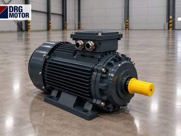
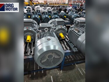
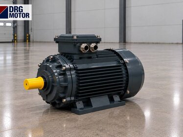
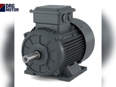
These four models cover the 0.25–0.75 kW range common on chip conveyors at 4-pole speed; the aluminium housing reduces the load on the gearbox flange. Note the frame step (71 / 80) when replacing.
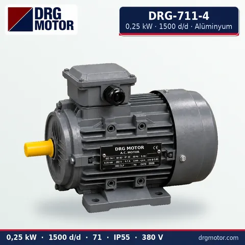
0.25 kW Three-Phase Motor 1500 rpm – DRG-711-4 Aluminium
- 0.25 kW · 1500 rpm (4 poles)
- Aluminium frame · IEC 71
- Mounting: B3 · B5 · B14 · B35
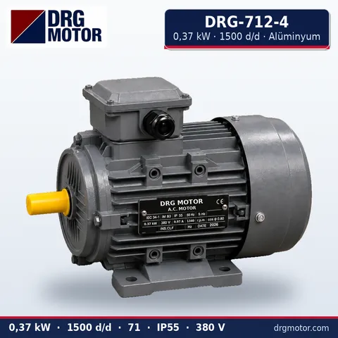
0.37 kW Three-Phase Motor 1500 rpm – DRG-712-4 Aluminium
- 0.37 kW · 1500 rpm (4 poles)
- Aluminium frame · IEC 71
- Mounting: B3 · B5 · B14 · B35
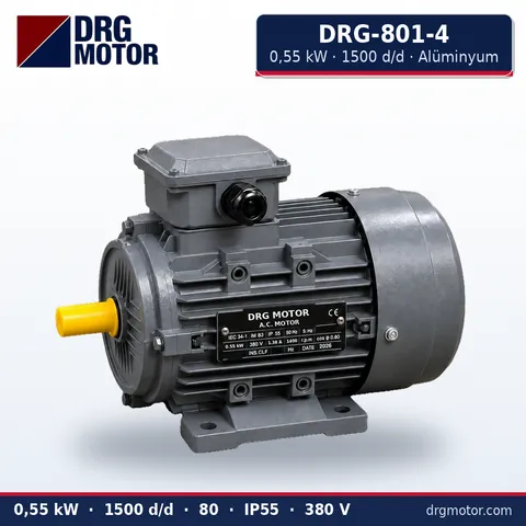
0.55 kW Three-Phase Motor 1500 rpm – DRG-801-4 Aluminium
- 0.55 kW · 1500 rpm (4 poles)
- Aluminium frame · IEC 80
- Mounting: B3 · B5 · B14 · B35
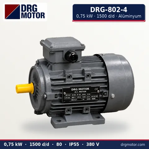
0.75 kW Three-Phase Motor 1500 rpm – DRG-802-4 Aluminium
- 0.75 kW · 1500 rpm (4 poles)
- Aluminium frame · IEC 80
- Mounting: B3 · B5 · B14 · B35
Click to see current prices and order these motors nowSEE PRICES →
Chip Conveyor Motor FAQ
Why does my chip conveyor motor keep tripping the overload?
In most cases the cause is mechanical, not the motor. A dry chain, chip sludge in the tank, wrapped long chips or a worn sprocket raise current. First turn the belt by hand to find the tight spot, then check that the overload setting matches the current on the motor nameplate.
What happens if the chip conveyor motor runs in reverse?
The belt carries chips back into the tank, towards the machine. If the belt runs backwards after a motor change, swapping two phases at the motor terminals is enough. Long reverse running can push the belt against the tank wall on types without a torque limiter.
Will a more powerful motor prevent jams?
No. A larger motor does not prevent a jam; it increases the force during one. Also, going from 0.37 kW to 0.55 kW changes frame and shaft diameter, so the motor may not fit the gearbox.
Can a chip conveyor motor run on an inverter?
Yes, DRG three-phase induction motors can be driven by an inverter. Builders who want to adjust belt speed to chip volume use one. Inverters are not part of the DRG range and are sourced separately.
To replace your motor, send a photo of the old nameplate, its power, speed, mounting (foot or flange), shaft size and conveyor type via WhatsApp, or add the models to the quote list. Phone: +90 (542) 666 11 11, e-mail: info@drgmotor.com. Other options are on the contact page. DRG Motor is a manufacturer, supplier and seller of electric motors; you can browse all models in the online store.