 English
 Le français
 Türkçe

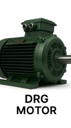
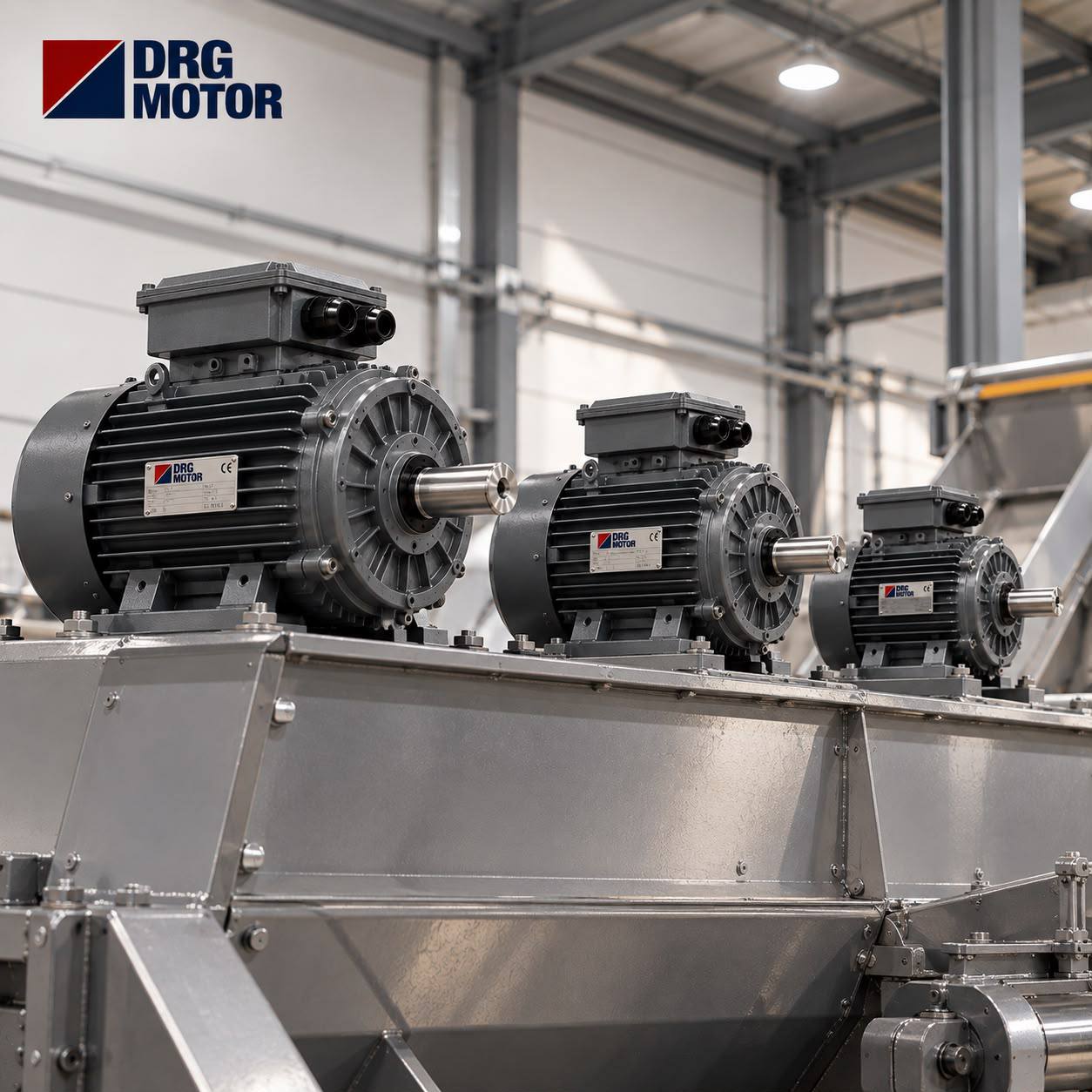

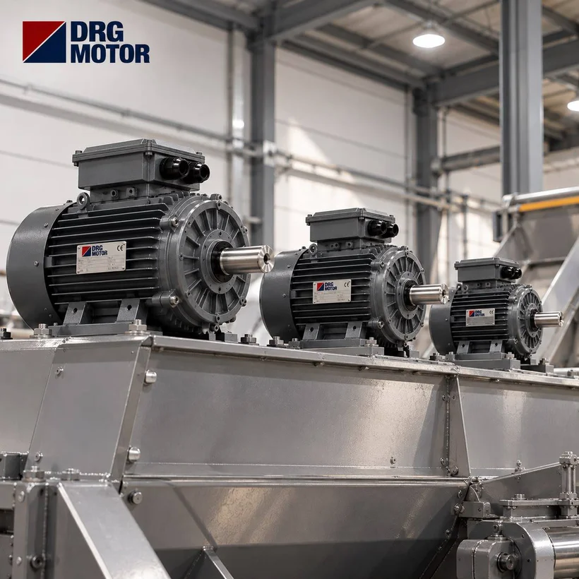
At a sand and gravel plant, an 8-degree inclined belt with a 400 mm drive pulley refuses to move at the first start of the morning; the thermal relay trips, the operator clears the belt by hand and tries again. On the evening shift the same belt turns easily when empty. When you look at the motor nameplate, the problem is usually not the power but another link in the chain: the wrong gearbox ratio makes the belt run faster than intended, the loaded starting torque was never considered, or the motor and gearbox do not meet on the same flange. In this article we treat the conveyor drive as a single chain: belt speed → pulley speed → gearbox ratio → pulling force → torque → power. We link each step with numbers and finish with a real model from the catalogue.
Six Pieces of Information to Collect on Site First
Before starting any calculation, write down the following. If any of them is missing, the resulting power figure is little more than a guess:
- Target belt speed v (m/s) and the allowed tolerance.
- Outer diameter D (mm) of the lagged drive pulley — including lagging thickness.
- The heaviest instantaneous load on the belt (kg) and the type of material (wet sand, crushed stone, cartons, crates).
- An approximate value for the moving mass of belt, idlers and pulleys.
- Inclination angle and whether the load is carried upwards or downwards.
- Input type of the existing gearbox (IEC flange size, bore diameter) or whether a new gearbox will be purchased.
From Belt Speed to Pulley Speed
Belt speed is the peripheral speed of the pulley. The formula is simple: npulley = v · 60 / (π · D). For example, with a target speed of 0.8 m/s and a pulley diameter of 0.40 m: 0.8 · 60 / (3.1416 · 0.40) ≈ 38.2 rpm. The most common mistake here is using the diameter of the bare steel pulley; 10 mm of rubber lagging increases the diameter by 20 mm and raises belt speed by about 0.04 m/s. On a short feed belt this looks negligible, but on a belt feeding a screen or a crusher it changes the feed rate.
Gearbox Ratio i: Calculated versus Available
The gearbox ratio is motor speed divided by pulley speed: i = nmotor / npulley. If the on-load speed of a 4-pole motor is taken as about 1450 rpm, 1450 / 38.2 ≈ 38. Instead of searching for a 38:1 gearbox, you move to a standard step; most manufacturers list 40. The actual pulley speed then becomes 1450 / 40 = 36.25 rpm and the actual belt speed 36.25 · π · 0.40 / 60 ≈ 0.76 m/s. This small reduction is usually acceptable; if not, the pulley diameter or frequency adjustment with a drive comes into play.
How many poles?
Choosing a 6-pole motor (about 1000 rpm) for the same pulley speed lowers the gearbox ratio (about 25–26 in this example), which can reduce gearbox size and noise; on the other hand, at the same kW a 6-pole motor has a larger frame and a higher price. A 2-pole motor requires a very high ratio and rarely makes sense on a conveyor. In practice, 4 poles is the balanced choice for most belts.
Pulling Force, Pulley Torque and Power: A Step-by-Step Example
Example belt: at most 2000 kg of material on the belt at once, an equivalent moving mass of 900 kg for belt + idlers + pulleys, 8° inclination, a simplified overall friction coefficient f = 0.04, pulley diameter 0.40 m, gearbox ratio 40, gearbox efficiency 0.90.
- Friction force: Fs = f · g · (mload + mmoving) · cos α = 0.04 · 9.81 · 2900 · cos 8° ≈ 1127 N.
- Lifting force: Fe = mload · g · sin α = 2000 · 9.81 · sin 8° ≈ 2731 N. Since the belt itself returns, only the material is lifted.
- Total pulling force: F = 1127 + 2731 ≈ 3857 N.
- Pulley torque: Tpulley = F · D / 2 = 3857 · 0.20 ≈ 771 Nm.
- Power at the pulley: P = F · v = 3857 · 0.76 ≈ 2.93 kW.
- Power at the motor shaft: 2.93 / 0.90 ≈ 3.25 kW.
- Torque at the motor shaft (steady state): 771 / (40 · 0.90) ≈ 21.4 Nm.
At first glance 4 kW looks sufficient. But stopping the calculation here is exactly the “belt that won’t start in the morning” story from the introduction. To try these steps with different values, you can use the power and torque calculators on the electric motor calculators page.
Starting a Loaded Belt: Where the Real Sizing Happens
On a stopped, loaded belt, the breakaway resistance is clearly higher than the running resistance because of idler bearings, scrapers and material trapped under the belt. For the example, take the friction share as 1.5 times at start: Fk = 2731 + 1.5 · 1127 ≈ 4421 N. Pulley torque is 4421 · 0.20 ≈ 884 Nm, and at the motor shaft 884 / (40 · 0.90) ≈ 24.6 Nm. This value only gets the belt moving; acceleration needs extra torque on top.
Let us compare with catalogue values: the rated torque of a 4 kW 4-pole motor is 26.3 Nm, which leaves only a small margin above the 24.6 Nm starting requirement. Applying a safety factor of 1.25 to 3.25 kW also gives 4.07 kW, so 4 kW falls short. The rated torque of a 5.5 kW 4-pole motor is 36.0 Nm, leaving comfortable margin for both acceleration and cold mornings. In this example the right choice is 5.5 kW. With a soft starter or a drive the starting current drops, but the required torque does not; when starting with a drive, also check the torque limit at low frequency.
Why a Backstop Is Essential on an Inclined Belt
When power is cut, a loaded inclined belt wants to run backwards. Let us be optimistic and lower the friction coefficient to 0.02: the holding friction is about 563 N, while the force pulling back is 2731 − 563 ≈ 2167 N. A reverse torque of about 433 Nm develops at the pulley. This torque piles material at the tail end, the reversing belt overflows the feed chute, and at restart the motor meets a load turning in the opposite direction.
- The backstop can be in the gearbox or on the pulley shaft; its rated holding torque must be at least the reverse torque, increased by the factor recommended by the gearbox manufacturer.
- On a gearbox with a backstop, check the motor’s direction of rotation uncoupled before assembly; a reversed phase loads the locked gearbox.
- A brake motor does not replace a backstop; they serve different purposes.
Gearbox and Motor Flange Compatibility
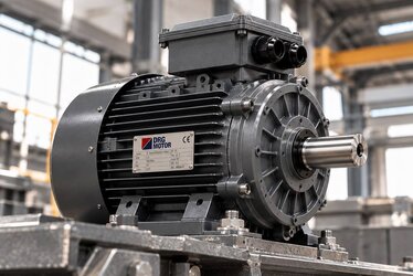
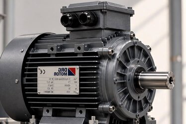
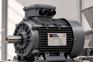
In most conveyor drives the motor is attached to the gearbox’s IEC input flange as B5 (large flange, clearance holes) or B14 (small flange, tapped holes). Before ordering, check: the motor frame size (e.g. 132S/132M share the same flange), shaft diameter and length (D × E), key size and flange type. If the gearbox input bore is 38 mm, a 132-frame motor fits; the 28 mm shaft of a 112-frame motor needs an adapter sleeve. The gearbox output torque capacity must also match what the motor can deliver: a 5.5 kW motor at a ratio of 40 can produce 36.0 · 40 · 0.90 ≈ 1296 Nm; the gearbox’s rated output torque is chosen above this value. In older drives with a foot-mounted (B3) motor and a coupling, shaft height and foot hole dimensions must match.
Example Models and Store Prices
The table below shows the powers commonly used from small parcel belts to medium-sized material belts. You can filter the full range by power and speed on the buy electric motors online page.
| Model | Power (kW) | Speed (rpm) | Housing | IEC | Rated torque (Nm) | excl. VAT | incl. VAT |
|---|---|---|---|---|---|---|---|
| DRG-90L-4 | 1.5 | 1500 | Aluminium | 90L | 9.91 | 6,210.75 TRY | 7,452.90 TRY |
| DRG-100L2-4 | 3 | 1500 | Aluminium | 100L | 19.8 | 8,783.25 TRY | 10,539.90 TRY |
| DRG-112M-4 | 4 | 1500 | Cast iron | 112M | 26.3 | 11,482.90 TRY | 13,779.48 TRY |
| DRG-132S-4 | 5.5 | 1500 | Cast iron | 132S | 36 | 15,438.50 TRY | 18,526.20 TRY |
| DRG-132M-4 | 7.5 | 1500 | Cast iron | 132M | 49.1 | 17,825.50 TRY | 21,390.60 TRY |
| DRG-160M-6 | 7.5 | 1000 | Cast iron | 160M | 73.8 | 26,158.00 TRY | 31,389.60 TRY |
Prices are taken from the DRG Motor online store list dated 24.09.2026; a 3% discount applies to bank transfer/EFT payments, shipping is not included in the price and is paid by the buyer.
For the 5.5 kW requirement in the example, the DRG-132S-4 in the table is suitable; if you want to reach the same pulley speed with a 6-pole motor and a lower-ratio gearbox, a larger frame in the 7.5 kW class such as the DRG-160M-6 comes into consideration. For a more general look at belt line layout and motor placement, see the article on choosing an electric motor for conveyors and belt lines.
Common Mistakes and Pre-Order Checklist
- Measuring the pulley without lagging and miscalculating belt speed.
- Sizing power from running resistance only and skipping loaded starting torque.
- Treating the calculated ratio as the purchased one; not checking how belt speed changes with the standard step.
- Skipping the backstop on an inclined belt because “there is a brake”.
- Not matching motor flange, shaft diameter and key to the gearbox input before ordering.
- Not asking about IP55 protection, cable entry direction and terminal box position on dusty open sites.
- Not evaluating whether a long belt needs multiple drives or a soft start with a drive.
Additional ambient conditions for belts on crushing and recovery lines are covered in the article on crusher and conveyor motor supply for recycling plants.
Frequently Asked Questions
Can I estimate conveyor motor power from belt length?
Length alone is not enough. Two belts of the same length can require very different power depending on the conveyed mass, inclination and idler condition. You need to calculate the pulling force from its friction and incline components, then work down to pulley torque and motor shaft torque.
What happens if the gearbox ratio does not match exactly?
With a standard ratio the belt speed changes by a few percent. If the process is sensitive to this, the pulley diameter or pulley ratio is changed, or the frequency is adjusted with a drive. When reducing speed with a drive, remember that the motor fan also slows down and heating may increase.
Should I choose a 4-pole or a 6-pole motor?
A 4-pole motor offers a smaller frame and a more affordable price at the same kW; the gearbox ratio is higher. A 6-pole motor lowers the gearbox ratio but the frame gets larger. The existing gearbox input flange and ratio decide the choice.
Is a brake motor enough on an inclined belt?
No. A brake is for controlled stopping and holding while the motor is powered; the element that mechanically prevents rollback when power is lost is the backstop. On loaded inclined belts the backstop is selected separately.
Send us your belt speed, pulley diameter, load and incline data and the flange size of your existing gearbox, and we will determine the right motor together: +90 (542) 666 11 11, [email protected] or our contact page.