 English
 Le français
 Türkçe




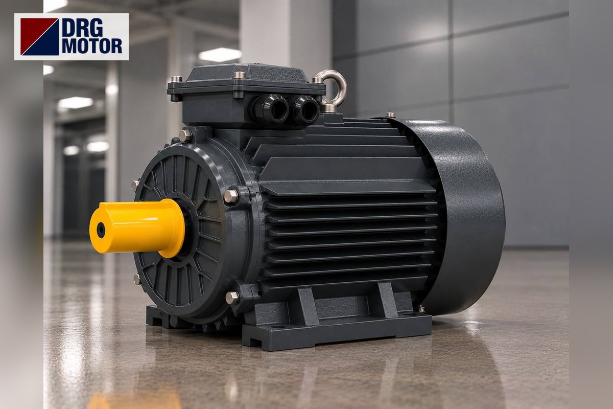

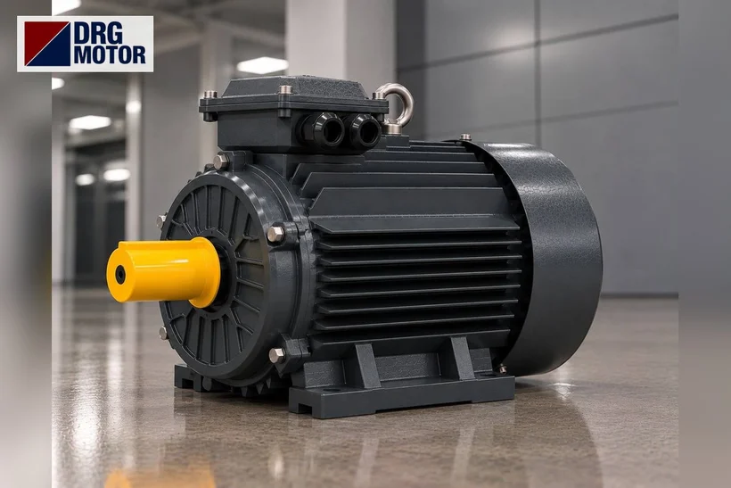
The spring-applied electromagnetic brake used on brake motors is fail-safe: springs hold the shaft and the brake only releases when its DC coil is energised. Because the coil needs DC, the AC supply is converted by a brake rectifier. The correct wiring depends on where the rectifier takes its supply from and whether the brake is switched on the AC side or the DC side.
Safety notice: This content is for technical information only. Wiring, measurement and commissioning must be carried out by qualified electrical personnel, following lock-out and verification of de-energised state, and in line with the motor and device manufacturer's documentation.
This article uses diagrams to explain how the brake works, half-wave and full-wave rectifiers, supply from the motor terminals versus a separate supply, AC-side versus DC-side switching and use with a drive. Terminal names in the diagrams are representative; they vary by device and the brake and rectifier maker's wiring diagram prevails. When a brake is actually needed is covered in when is a brake electric motor needed.
How does a spring-applied electromagnetic brake work?
The brake is a unit fitted to the fan-side end shield. A lined disc keyed to the shaft sits between a fixed friction face and an armature plate that can slide axially. Springs behind the armature press it onto the disc, and the disc onto the friction face, so the shaft is locked. When DC voltage reaches the coil in the magnet body, the armature is pulled back against the springs, the disc is freed and the motor can turn.
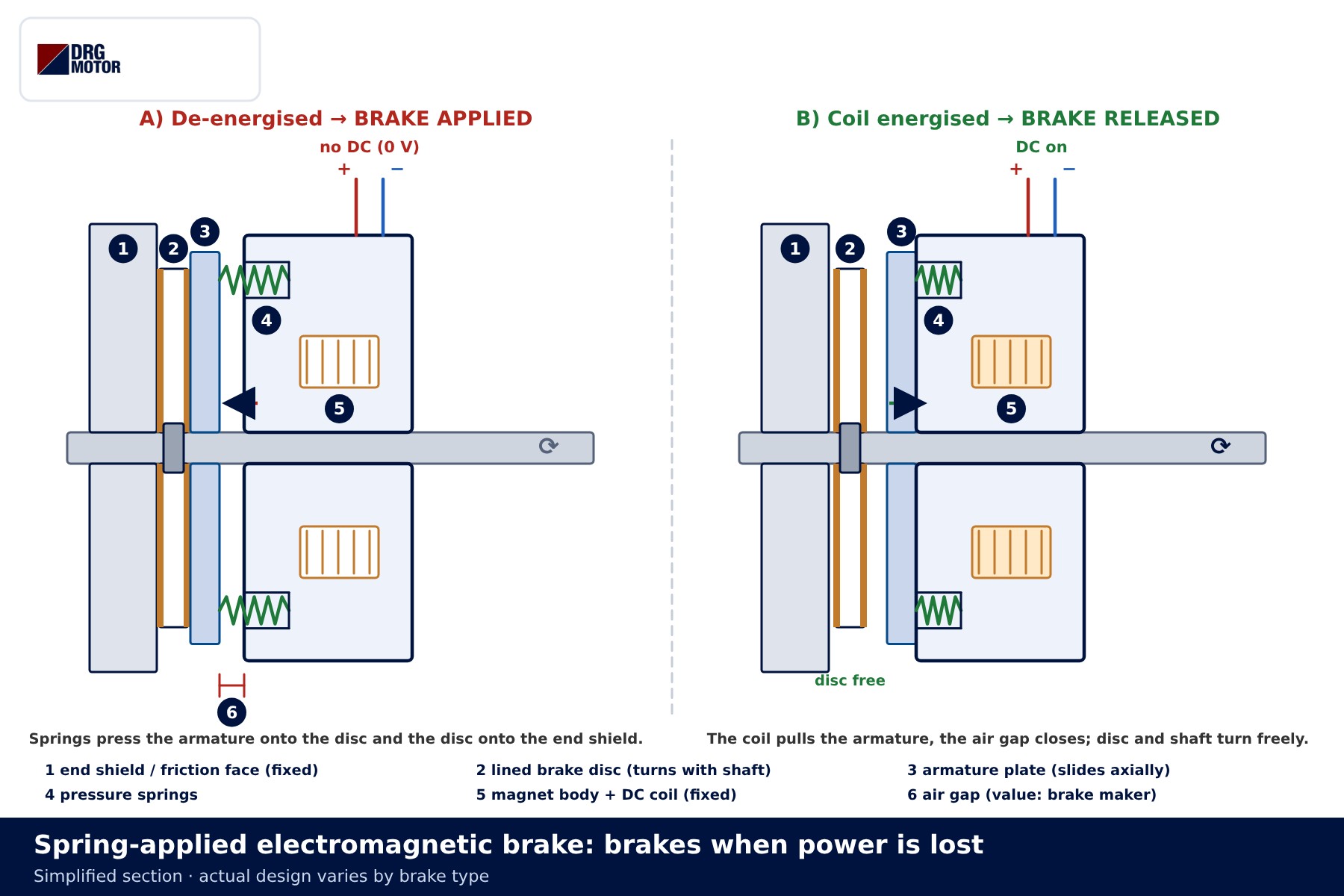
The key consequence: the brake is open when voltage is present and closed when it is not. A power cut, a broken wire or a failed rectifier all leave the load held. The air gap between armature and magnet body grows as the lining wears; beyond a certain limit the coil can no longer pull the armature and the brake will not release. The gap value and adjustment method belong to the brake maker; see brake motor air gap adjustment for details.
| Component | Terminals (representative) | Function |
|---|---|---|
| Q1 motor protection breaker | 1-2 / 3-4 / 5-6, 95-96 | Protects the motor against short circuit and overload |
| K1 motor contactor | A1-A2, 1…6, 13-14, 23-24 | Connects the motor; its auxiliary contact drives K2 |
| K2 brake contactor | A1-A2, 1-2, 3-4, 13-14 | Switches the brake supply; can also break the DC side |
| F4 brake fuse | single pole | Protects the separate brake line |
| G1 brake rectifier | ~ ~ / + − | Converts AC into DC for the coil |
| Y1 brake coil | + − | Pulls the armature when energised, releasing the brake |
Brake rectifier: half-wave and full-wave
In a half-wave rectifier a single diode passes only the positive half-cycles; a freewheel diode connected in reverse across the coil keeps the coil current flowing during the other half-cycle. The ideal average DC voltage is about 0.45 times the AC value. A full-wave (bridge) rectifier uses four diodes and both half-cycles, raising the average to about 0.9 times.
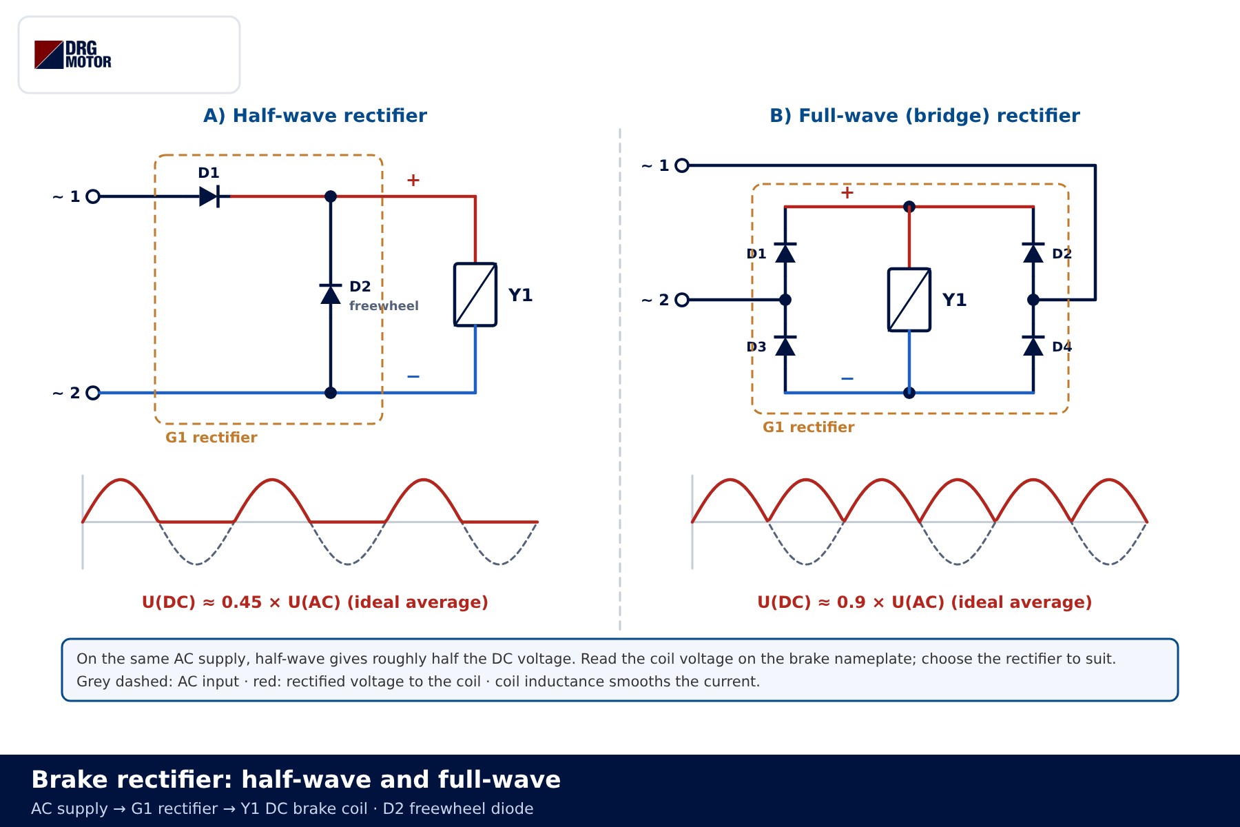
In practice the choice starts from the coil voltage. The brake nameplate gives the coil DC voltage and the matching AC supply for the rectifier; the rectifier type follows from the ratio between the two. Swapping in another brake's rectifier without reading the nameplate can leave the coil unable to release or make it overheat. Some rectifiers briefly apply a higher voltage at switch-on and then drop to the holding level; with these, terminal wiring follows the maker's diagram exactly.
📄 Download Wiring Diagram PDF A4 printable PDF of the diagrams and tables (no sign-up)
Should the rectifier be fed from the motor terminals or a separate line?
On small direct-on-line motors the rectifier AC input is often wired to two motor terminals inside the terminal box. The brake then releases as soon as K1 closes, with no extra contactor or cable. The rectifier's AC input voltage must match the voltage across the terminals it is connected to, which depends on the star or delta connection of the motor.
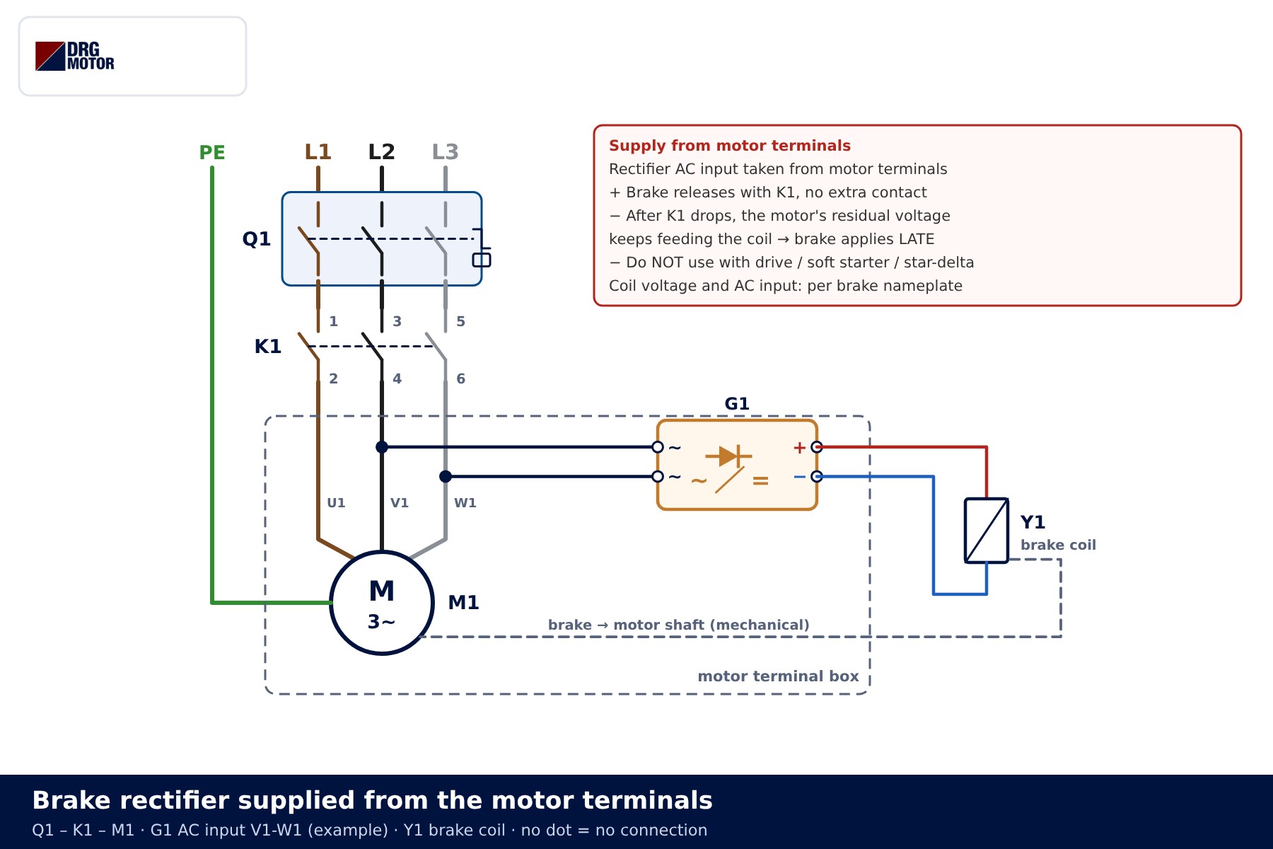
This arrangement has a known weakness. When K1 drops out the motor is still turning, and residual magnetism in the windings generates voltage for a short while. That voltage keeps feeding the rectifier, so the brake applies late. And if the terminal voltage changes during starting (star-delta changeover, soft starter ramp, drive output), the brake can open or close at the wrong moment.
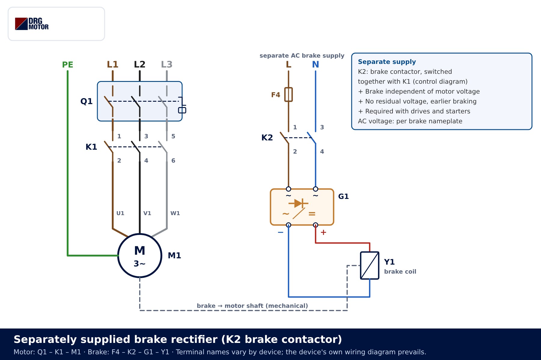
With a separate supply the rectifier is fed from its own AC line through its own fuse (F4) and contactor (K2). The brake is independent of the motor voltage, there is no residual-voltage delay and DC-side switching is easy to add. This is the method for every application with a starter or drive. For the star-delta circuit itself, see the star-delta power circuit.
Click to see current electric motor prices and order nowSEE PRICES →
AC-side switching versus DC-side switching
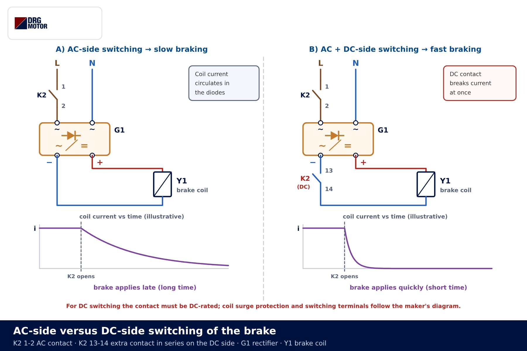
What sets the brake application time is how quickly the coil current falls to zero. With AC-side switching (K2 1-2 only) the rectifier input opens, but the energy stored in the coil circulates through the diodes and decays slowly. The brake applies softly and late, which is acceptable for horizontal motion where stopping distance is not critical.
With DC-side switching a second contact (K2 13-14 in the diagram) is placed in series with the coil. When K2 drops out the current path is broken directly, the current dies away very quickly and the brake applies fast. This is generally preferred for vertical loads and wherever a short stopping distance is required; the method an application needs is set by the machine and brake maker's documents. The contact breaking DC must be rated for DC switching, and because a high voltage appears across the coil at the moment of breaking, the protective element and switching terminals are wired to the maker's diagram.
Selection examples
| Application | Rectifier supply | Switching |
|---|---|---|
| Direct-on-line horizontal conveyor | Motor terminals or separate | AC side may be enough |
| Machine axis needing a short stop | Separate (K2) | AC + DC side |
| Vertical load, lifting motion | Separate (K2) | AC + DC side; the maker's diagram prevails |
| Drive, soft starter or star-delta | Always separate | Per application; sequence per device maker |
Control circuit and operating sequence
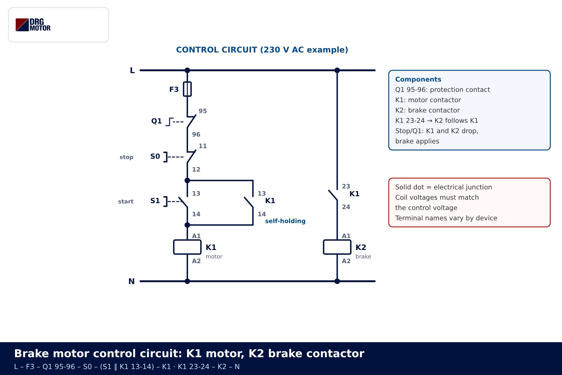
The control for a separately supplied brake is the familiar start-stop circuit with one extra rung. K1, the motor contactor, works with the stop button, the start button and its 13-14 self-holding contact; K1's second auxiliary contact 23-24 feeds the coil of K2, the brake contactor. K2 therefore picks up and drops out together with K1.
- Standby: K1 and K2 are de-energised, there is no coil current and the springs hold the shaft.
- Start button pressed: K1 picks up and seals in; 23-24 closes, K2 picks up and the rectifier is supplied. Coil current rises, the brake releases after a short release delay and the motor accelerates.
- Running: the coil current is steady and the brake stays released.
- Stop button or Q1 trip: K1 and K2 drop out. With AC switching the brake applies late, with DC switching at once.
- Mains failure: all supplies are lost and the brake applies by itself; when power returns the motor waits for a new start.
State table and timing diagram
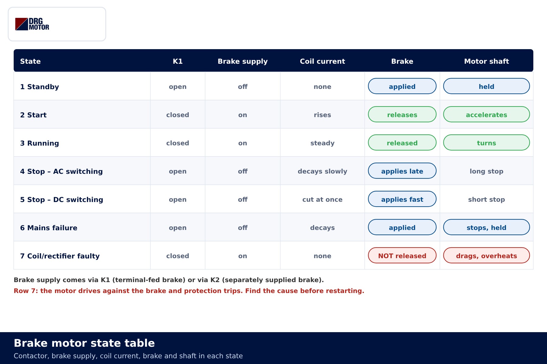
| State | Brake supply | Brake | Motor shaft |
|---|---|---|---|
| Standby | off | applied | held |
| Start | on | releases | accelerates |
| Stop – AC switching | off | applies late | stops over a longer time |
| Stop – DC switching | off | applies fast | stops quickly |
| Coil or rectifier faulty | on | does not release | drives against the brake, protection trips |
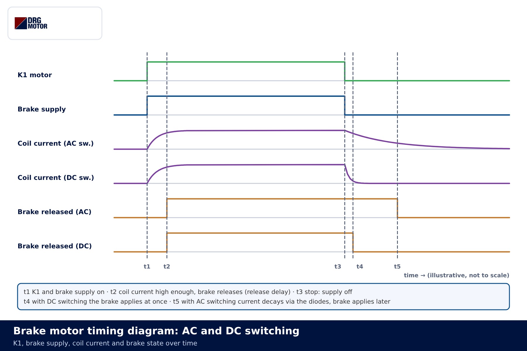
In the timing diagram K1 and the brake supply come on at t1, and at t2 the coil current is high enough for the brake to release. Stop is given at t3; with DC switching the brake applies straight away at t4, while with AC switching it applies later, at t5, because the current decays through the diodes. The diagram is illustrative; real times depend on the brake type and coil.
Why is the brake fed separately when a drive is used?
A drive varies output voltage and frequency with motor speed, so the voltage is low at low speed. A rectifier fed from that output cannot release the brake fully; the lining drags and heats up. Fast switching at the drive output can also damage the rectifier. The brake is therefore always fed from a separate AC line, and K2 is driven by the drive's relay output intended for brake control. The release and apply sequence (torque first, then release; at stop, brake first, then output off) is set according to the drive maker's documents; no parameter values are given here.
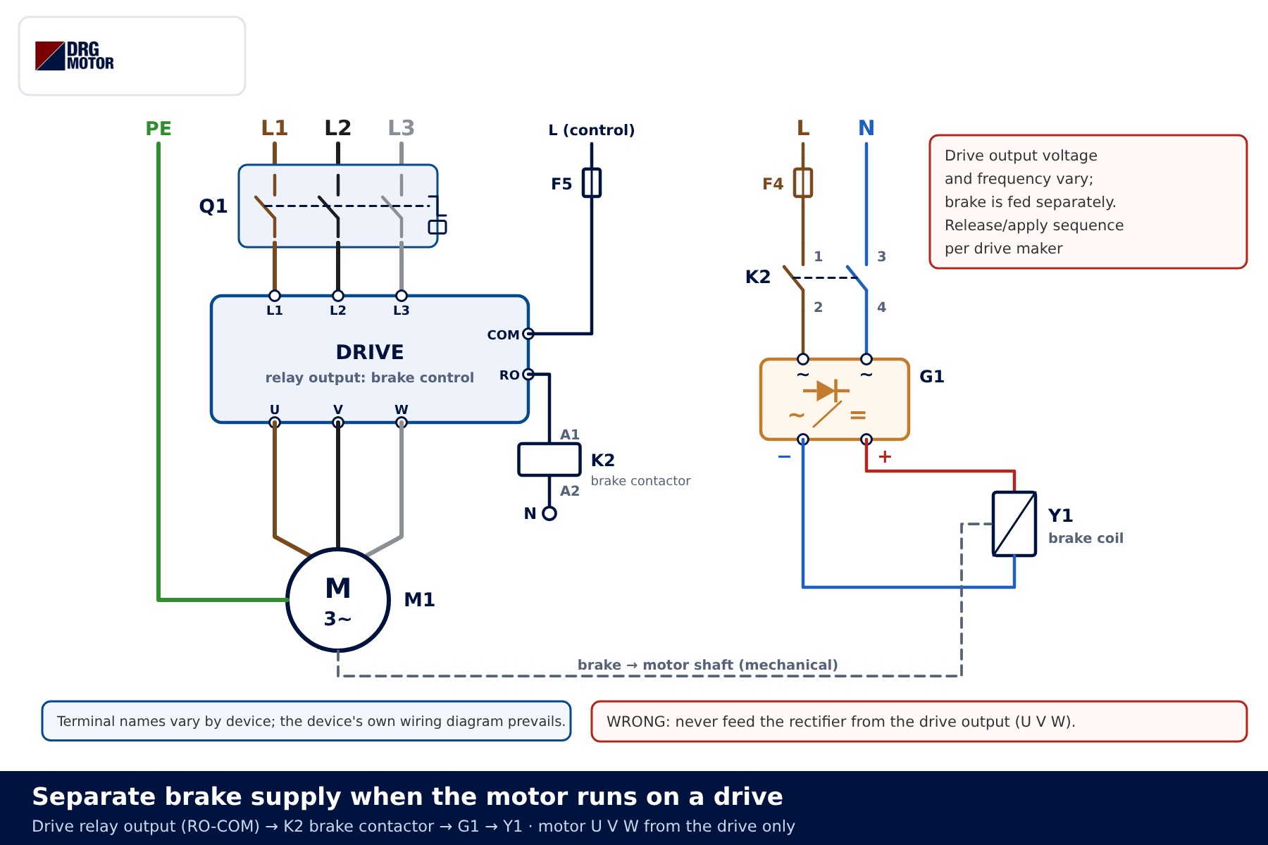
Do not confuse this brake with the drive dissipating energy in a resistor during deceleration; that topic is covered in dynamic braking and braking resistors on inverters. The drive slows the motion; the mechanical brake holds the load once it has stopped.
Coil voltage, air gap and nameplate data
Before wiring, check three items on the brake nameplate: the coil DC voltage, the AC supply intended for the rectifier and the braking torque. No values are given here because the same frame size can carry brakes with different coil voltages. If a measurement is needed, the DC voltage at the coil terminals is measured by qualified personnel with a DC voltmeter and is not to be confused with the AC input. The air gap grows as the lining wears; late release, humming or no release at all usually means the gap has passed its adjustment limit.
Common wiring mistakes
| Symptom | Likely cause |
|---|---|
| Motor runs but the brake does not release, motor heats up | No rectifier supply, open coil, wrong coil voltage or air gap beyond its limit |
| Brake applies very late at stop | Rectifier fed from the motor terminals (residual voltage) or switched on the AC side only |
| On a drive, the brake drags at low speed | Rectifier fed from the drive output (U V W) |
| Brake closes briefly at star-delta changeover | Rectifier wired to the motor terminals; voltage is lost during changeover |
| Arcing on the DC contact, rectifier failure | Contact not rated for DC switching or no coil protection element |
| Brake releases weakly after a rectifier change | Full-wave fitted instead of half-wave (or the reverse); output does not match the coil |
If the motor keeps running against a closed brake, its protection will trip; find the cause before restarting. Other reasons for repeated overload trips are listed in why an electric motor trips the overload relay. To size protective devices use the overload, fuse and contactor selection tool, and for cabling the motor cable size calculator; no single cross-section fits every installation.
📄 Download Wiring Diagram PDF A4 printable PDF of the diagrams and tables (no sign-up)
Send a photo of your current motor nameplate and we will find the suitable DRG model together.Send on WhatsApp
DRG three-phase motors for braking applications
DRG Motor is an electric motor manufacturer, supplier and seller. Brake motors and brake rectifiers are not part of DRG's standard range. Where a brake is needed, DRG three-phase IEC motors can be considered; the brake unit and rectifier are sourced separately, their suitability for the motor is checked with the brake maker, and wiring follows the brake maker's diagram. For contactors, fuses and drives, please contact your panel component supplier. Other ratings are listed on the three-phase asynchronous electric motors page and in the online store.
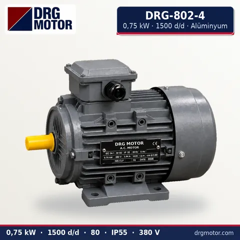
0.75 kW Three-Phase Motor 1500 rpm – DRG-802-4 Aluminium
- 0.75 kW · 1500 rpm (4 poles)
- Aluminium frame · IEC 80
- Mounting: B3 · B5 · B14 · B35
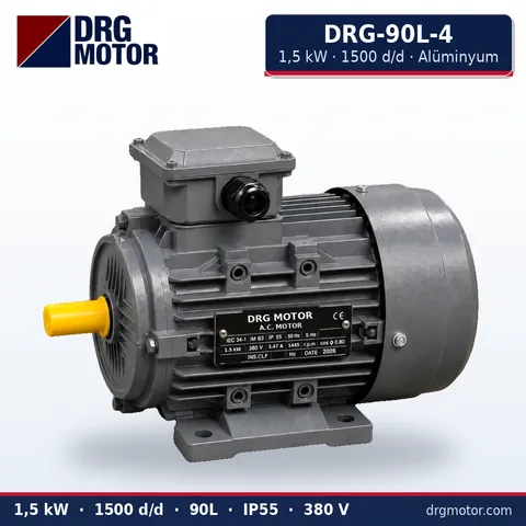
1.5 kW Three-Phase Motor 1500 rpm – DRG-90L-4 Aluminium
- 1.5 kW · 1500 rpm (4 poles)
- Aluminium frame · IEC 90L
- Mounting: B3 · B5 · B14 · B35
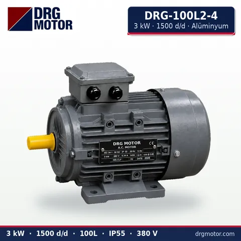
3 kW Three-Phase Motor 1500 rpm – DRG-100L2-4 Aluminium
- 3 kW · 1500 rpm (4 poles)
- Aluminium frame · IEC 100L
- Mounting: B3 · B5 · B14 · B35
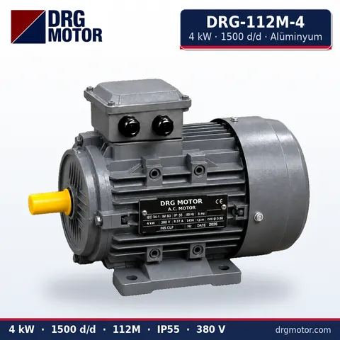
4 kW Three-Phase Motor 1500 rpm – DRG-112M-4 Aluminium
- 4 kW · 1500 rpm (4 poles)
- Aluminium frame · IEC 112M
- Mounting: B3 · B5 · B14 · B35
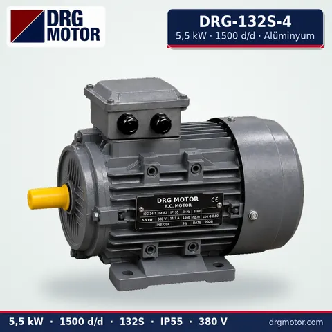
5.5 kW Three-Phase Motor 1500 rpm – DRG-132S-4 Aluminium
- 5.5 kW · 1500 rpm (4 poles)
- Aluminium frame · IEC 132S
- Mounting: B3 · B5 · B14 · B35
Click to see current prices for these motors and order nowSEE PRICES →
Frequently asked questions
Why is the brake closed when there is no power?
In a spring-applied brake the springs provide the holding force; the coil is energised only to release the brake. If power is lost or a wire breaks, the load stays held.
Should I use a half-wave or a full-wave rectifier?
It depends on the ratio between the coil DC voltage and the available AC supply. On the same supply, half-wave gives roughly half the average voltage. The right type is taken from the brake nameplate and the brake maker's diagram.
Is it wrong to connect the brake rectifier to the motor terminals?
On direct-on-line motors it is a common and valid method; its only drawback is the delayed braking caused by residual voltage. It is not used with drives, soft starters or star-delta starting, where the brake is fed separately.
Is DC-side switching always required?
No. For horizontal motion where stopping distance does not matter, AC-side switching may be enough. DC-side switching is preferred for vertical loads and precise positioning; the decision follows the machine and brake maker's documents.





