English
 Le français
 Türkçe


The winding resistance of a three-phase motor means measuring the copper resistance of the three phase windings — labelled U-V-W — one by one with an ohmmeter (or a micro-ohmmeter for very low values). In a healthy motor these three values come out very close to each other; a marked difference between them points to a short circuit, an open winding or a degraded connection in one of them. This article explains, as information, what the winding resistance test tells you and how the results are interpreted.
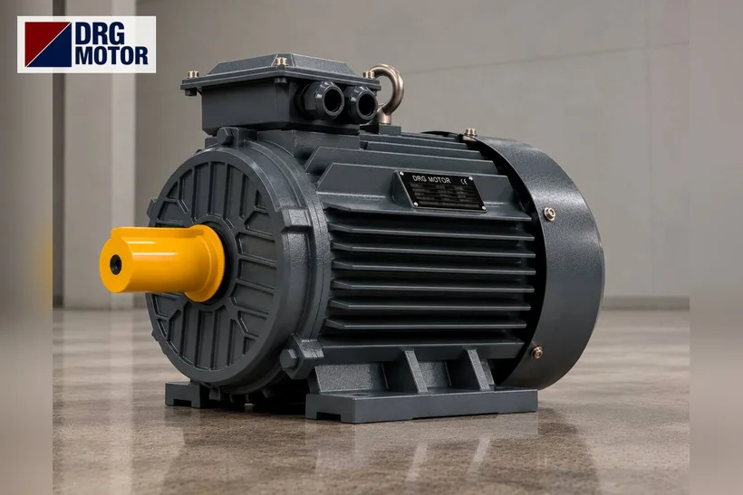
DRG Motor is a manufacturer, supplier and seller of electric motors. If a motor whose winding cannot be repaired has to be renewed, you can select a suitable power from the online motor shop and see all models together in the three-phase asynchronous electric motors category.
What is winding resistance and what does it show?
Winding resistance is the ohmic resistance of the copper wire that forms the motor winding itself. Since each phase winding is a conductor wound to a certain length and cross-section, it has a small but measurable resistance in ohms. This value depends on the wire's length, cross-section and temperature. Because the three phase windings are made with the same wire and the same number of turns, in a sound factory-fresh motor the resistance of the three windings is almost identical.
The aim of the measurement is not to catch an absolute figure but to see the balance of the three windings relative to each other. A small spread between the windings is normal; a large, unexplained difference is the first sign of a problem inside a winding.
Winding resistance is not the same as insulation resistance
These two measurements are often confused but describe different things. Winding resistance is the winding's own copper resistance, in the order of ohms (Ω), measured with an ordinary ohmmeter between the phase windings. Insulation resistance, on the other hand, is the soundness of the insulation between the winding and the frame (earth), in the order of megohms (MΩ), measured with a separate insulation tester. In short, winding resistance questions the winding's conductivity, while insulation resistance questions the integrity of the insulation. The subject of this article is the former — the ohmic resistance of the winding.
Before measuring: switch off the supply
Winding resistance is always measured de-energised. Switch off the relevant breaker in the panel, confirm the de-energised state with a suitable instrument and apply lock-out/tag-out where possible. If the motor is fed from a drive (inverter), allow the time needed for the DC-link capacitors to discharge. All of this must be carried out only by qualified electrical personnel; this article is not a field instruction but a guide to the logic of the measurement.
Measuring U-V-W winding resistances with an ohmmeter
Once the supply is off and the terminal box is open, the link (bar) connections that join the winding ends are removed; otherwise the three windings stay interconnected and cannot be measured individually. The ohmmeter is then applied across the winding ends. On the standard terminal plate the phase windings correspond as follows:
- Phase U: between U1 and U2
- Phase V: between V1 and V2
- Phase W: between W1 and W2
Because winding resistances are often a few ohms or less, the probe and lead resistance of the instrument can affect the result. On small motors an ordinary ohmmeter gives an idea; for very low resistances a micro-ohmmeter using a four-wire (Kelvin) measurement is more accurate. The three readings should be taken under the same conditions, with the same instrument and while the motor is at the same temperature, so the comparison is meaningful.
Click to see current electric motor prices and order nowSEE PRICES →
The three values should be close: what imbalance tells you
At the end you have three numbers: RU, RV, RW. In a healthy winding these three values are close. In the assessment, the percentage difference between them matters more than the absolute figure. If the three values diverge markedly, there is an imbalance in the winding and its cause must be investigated. Rather than fixing the acceptable deviation limit with a figure from memory, it is correct to interpret it according to the motor manufacturer's data and the instrument's documentation.
An unbalanced winding is not merely a measurement scatter; during operation it makes the phases draw different currents, leading to heating and vibration. So a clear imbalance is a finding to take seriously even if the motor still turns.
Diagnosing short circuit and open circuit
Comparing the three winding values helps to distinguish two typical internal faults:
- Turn-to-turn short circuit: Touching turns in a winding reduce the effective number of turns, and that winding's resistance comes out lower than the others. A phase read markedly low can be a sign of a turn-to-turn short.
- Open circuit: If there is a break in a winding or its connection, the ohmmeter reads very high or infinite (open circuit) across those ends. This shows the winding or a connection is electrically interrupted.
To keep the measurement from misleading you, when a value reads high or low the link connections, cable lugs and tightening torques are reviewed first, because a loose or oxidised connection can also look like a winding fault. If the difference persists while the connections are sound, the problem is in the winding itself.
Factors that affect the measurement
For a sound comparison you need to know what influences the measurement:
- Temperature: Copper resistance rises with temperature. A warm motor that just stopped and a cold motor give different values; the three phases should therefore be measured at the same temperature, one after another.
- Link connections: A measurement taken without removing the star/delta links shows the windings as parallel/series and misleads.
- Probe and lead resistance: At very low winding resistances the instrument's own resistance adds to the result; a four-wire measurement removes this.
- Contact quality: Oxidised or loose ends make the value read higher than it is.
Winding checks on DRG three-phase models
A winding resistance test is the first step in deciding whether a motor can be serviced. Below are the power, pole/speed and 400 V rated current values of common DRG aluminium-housing models in the 1500 rpm (4-pole) class; these serve as a reference when you compare the operating current you measure. The voltage on all of them is 400/690 V (Δ/Y).
| Model | Power | Poles / Speed | Rated current (400 V) |
|---|---|---|---|
| DRG-112M-4-AL | 4.0 kW | 4 / 1500 rpm | 7.95 A |
| DRG-132S-4-AL | 5.5 kW | 4 / 1500 rpm | 10.7 A |
| DRG-112M-4K-AL | 5.5 kW | 4 / 1500 rpm | 10.7 A |
| DRG-132M-4-AL | 7.5 kW | 4 / 1500 rpm | 14.3 A |
| DRG-160M-4-AL | 11.0 kW | 4 / 1500 rpm | 20.4 A |
| DRG-132M-4K-AL | 11.0 kW | 4 / 1500 rpm | 20.4 A |
To compare the current or power you measure with these values, the motor current chart and electric motor calculator tools are a useful guide. If a motor with a permanently damaged winding has to be renewed, base the choice on the power, speed, housing and connection on the existing motor's nameplate.
Send a photo of your current motor nameplate and we will find the suitable DRG model together.Send on WhatsApp
Once you have identified the right replacement motor from the measurement result, you can compare all power and speed options and current prices through the shop.
If a motor with a faulty winding must be renewed, compare the three-phase asynchronous models and current prices in the shopSEE PRICES
Frequently asked questions
How many ohms should the winding resistance be?
There is no single correct figure; the value depends on the motor's power, number of turns and temperature. What matters is that the three phases are close to each other. For the acceptance limit, refer to the motor manufacturer's data and the instrument's documentation.
What is the difference between winding resistance and insulation resistance?
Winding resistance is the winding's own copper resistance, in the order of ohms, measured across the phases. Insulation resistance is the resistance of the insulation between the winding and the frame, in the order of megohms, measured with a separate instrument. The two reveal different faults.
What does it mean if one phase reads a low resistance?
A phase read markedly low suggests there may be a turn-to-turn short in that winding. The link connections and terminals are checked first; if the problem is not there, a winding fault is likely.
Can I measure the winding resistance myself?
The measurement must be done de-energised and with the correct method. No work should be done without switching off the supply and confirming the de-energised state; measurement and connection tasks should be carried out by qualified electrical personnel.
Electric Motors Related to This Topic — Models and Current Prices
Suitability is not decided by power alone: compare the speed, voltage, mounting, shaft and fixing dimensions of your machine with the product data; if unsure, send us the nameplate of your current motor.
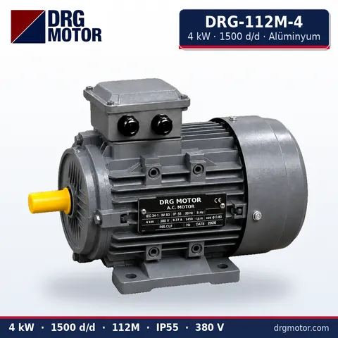
4 kW Three-Phase Motor 1500 rpm – DRG-112M-4 Aluminium
- 4 kW · 1500 rpm (4 poles)
- Aluminium frame · IEC 112M
- Shaft: 28 × 60 mm
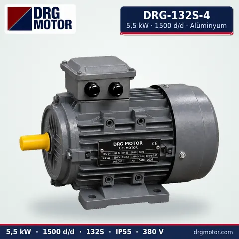
5.5 kW Three-Phase Motor 1500 rpm – DRG-132S-4 Aluminium
- 5.5 kW · 1500 rpm (4 poles)
- Aluminium frame · IEC 132S
- Shaft: 38 × 80 mm
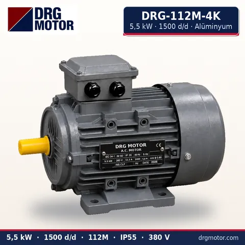
5.5 kW Compact Three-Phase Motor 1500 rpm – DRG-112M-4K Aluminium
- 5.5 kW · 1500 rpm (4 poles)
- Aluminium frame · IEC 112M
- Shaft: 28 × 60 mm
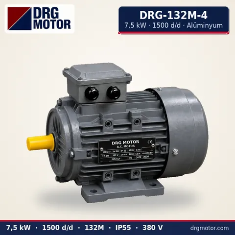
7.5 kW Three-Phase Motor 1500 rpm – DRG-132M-4 Aluminium
- 7.5 kW · 1500 rpm (4 poles)
- Aluminium frame · IEC 132M
- Shaft: 38 × 80 mm
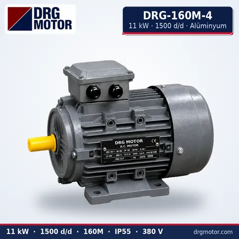
11 kW Three-Phase Motor 1500 rpm – DRG-160M-4 Aluminium
- 11 kW · 1500 rpm (4 poles)
- Aluminium frame · IEC 160M
- Shaft: 42 × 110 mm
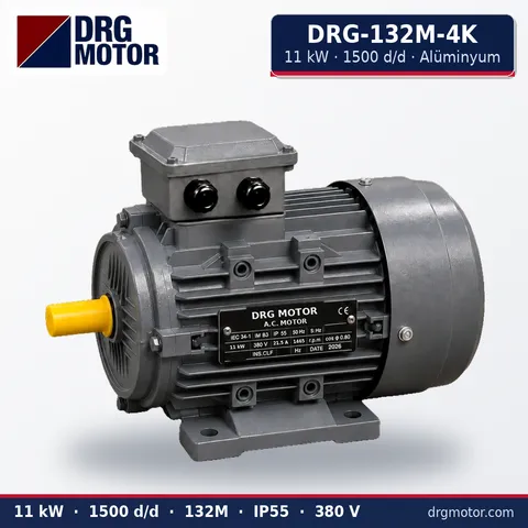
11 kW Compact Three-Phase Motor 1500 rpm – DRG-132M-4K Aluminium
- 11 kW · 1500 rpm (4 poles)
- Aluminium frame · IEC 132M
- Shaft: 38 × 80 mm