 English
 Le français
 Türkçe




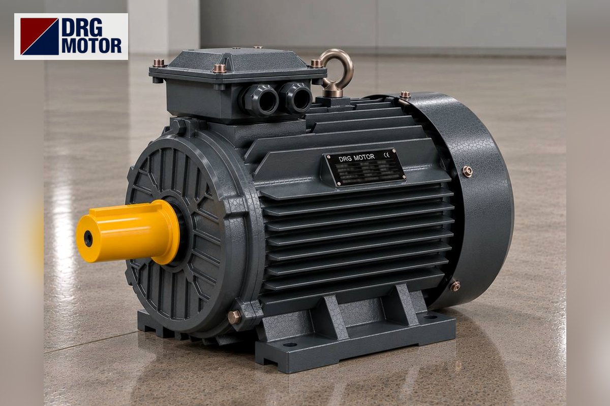

The U1-V1-W1 and U2-V2-W2 markings you see in a three-phase motor terminal box are the start and finish ends of the three windings; they let the motor be bridged correctly in star or delta. On older motors the same ends are written U-V-W and X-Y-Z. Cable colours are only a helper and never replace these markings.
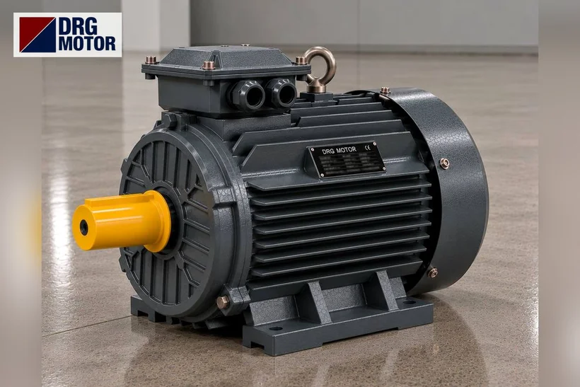
DRG Motor is a manufacturer, supplier and seller of electric motors. You can review every three-phase asynchronous motor whose terminals you are checking, by power and speed, in the online motor shop, and see the same models together in the three-phase asynchronous electric motors category.
What do U1-V1-W1 and U2-V2-W2 mean?
A three-phase asynchronous motor has three separate windings inside. Both ends of each winding are brought out to the terminal board, so there are six ends and six screws in total. In current IEC marking, the winding starts are U1, V1, W1 and the winding finishes are U2, V2, W2. In other words U1 and U2 are the two ends of the same winding, and so are V1-V2 and W1-W2.
The ends are placed in a crossed order on the board: the top row usually carries U1-V1-W1 and the bottom row W2-U2-V2. This layout lets the bridge links (bars) be set either straight or across, so star or delta can be made quickly. Because the physical order can differ slightly between brands, always rely on the stamped markings on the board.
How do old U-V-W / X-Y-Z map to new U1-V1-W1?
On older motors, or on some replacement parts, the markings may be written differently. In the old system the winding starts were U, V, W and the finishes were X, Y, Z. Functionally these ends are the exact equivalents of the new marking; only the names changed. The table below places the two notations side by side.
| Winding / Phase | New marking (start–finish) | Old marking |
|---|---|---|
| Phase 1 | U1 – U2 | U – X |
| Phase 2 | V1 – V2 | V – Y |
| Phase 3 | W1 – W2 | W – Z |
When replacing a motor and you see U-V-W / X-Y-Z on the old board, there is no need to worry: you can read U1=U, V1=V, W1=W and U2=X, V2=Y, W2=Z. The key is to know correctly which two ends belong to the same winding.
How are the markings linked to star and delta bridging?
The way the six ends are bridged decides whether the motor runs in star or delta. The two basic cases are:
- Star (Y) connection: the winding finishes U2-V2-W2 are joined together with three links to form a common point (the star point). Supply phases feed the U1-V1-W1 ends.
- Delta (Δ) connection: the links join each winding finish to the next winding start (U1-W2, V1-U2, W1-V2). Supply phases are again given to the U1-V1-W1 ends.
Which connection to choose depends on the voltage printed on the nameplate and on the mains voltage. You can find the exact link positions and the diagram detail step by step in our three-phase motor wiring diagram and terminal links and star and delta connection at the motor terminals articles.
Click to see current electric motor prices and order nowSEE PRICES →
Cable and terminal colour codes: idea and limits
On supply cables, colours help to tell the phases and the protective conductor apart. In common practice the protective earth conductor is green-yellow and the neutral (if used) is light blue. Brown, black and grey are often seen for the phase conductors. However, the colour rule can change by country, cable type and installation date, so it is wrong to impose any colour as a fixed rule.
At the motor's own output ends the stamped letter markings (U1-V1-W1…) govern, not the colour. Instead of guessing a phase by its colour, the safest path is to read the marking on the terminal board and verify the direction of rotation under control. If two phases swap places the motor turns the other way; this is corrected only by looking at the markings and by measurement. To check phase-neutral and phase-phase values you can use the motor current chart tool.
DRG models marked 400/690 V and the terminal box
The markings in the terminal box work the same way whatever the model. The 4-pole (1500 rpm class) DRG models below are wound 400/690 V (Δ/Y); that is, they run in delta (Δ) bridging on a 400 V three-phase mains. Each model's rated current and connection voltage are in the table, and the model codes link straight to the product page.
| Model | Power | Rated current (400 V) | Connection voltage |
|---|---|---|---|
| DRG-112M-4 (DRG-112M-4-AL) (aluminium) | 4 kW | 7.95 A | 400/690 V (Δ/Y) |
| DRG-132S-4 (DRG-132S-4-AL) (aluminium) | 5.5 kW | 10.7 A | 400/690 V (Δ/Y) |
| DRG-112M-4K (DRG-112M-4K-AL) (aluminium) | 5.5 kW | 10.7 A | 400/690 V (Δ/Y) |
| DRG-132M-4 (DRG-132M-4-AL) (aluminium) | 7.5 kW | 14.3 A | 400/690 V (Δ/Y) |
| DRG-160M-4 (DRG-160M-4-AL) (aluminium) | 11 kW | 20.4 A | 400/690 V (Δ/Y) |
| DRG-132M-4K (DRG-132M-4K-AL) (aluminium) | 11 kW | 20.4 A | 400/690 V (Δ/Y) |
The current values in the table are approximate; always check the motor nameplate for the exact value. On small-power models marked 230/400 V, star (Y) connection is used on a 400 V mains; the nameplate decides this choice.
A note on safe connection
Reading the markings is for information; the actual connection is site work. Before any terminal work, switch off the supply, verify the absence of voltage with a suitable device, and have only authorised electrical personnel make the connection. Apply the bridge links, cable lugs and tightening torque according to the motor nameplate and panel documents; set values such as the thermal protection current from the rated current on the nameplate, not from memory.
Send a photo of your current motor nameplate and we will find the suitable DRG model together.Send on WhatsApp
Compare the suitable three-phase DRG model and current prices in the shop for the motor whose terminals you are readingSEE PRICES
Frequently asked questions
Are U1-V1-W1 and U-V-W the same thing?
Functionally yes. U1, V1, W1 are the winding starts in current IEC marking; in the old system these were written U, V, W. The winding finishes are U2-V2-W2 in the new system and X-Y-Z in the old one.
What are the terminal links for?
The links (bars) are metal parts that join the six winding ends to form either star or delta. The position of the links decides which connection the motor runs in; the detailed diagram is in our wiring diagram article.
Can I tell the phase from the cable colour?
Colours help but are not definitive; the colour rule can change with the installation. On the motor side, the stamped U1-V1-W1 markings on the terminal board are what matter. Do not assume a phase from colour alone.
What happens if I swap two phases?
In a three-phase motor, if any two phase ends are swapped the motor turns the other way. Correcting the direction is done by switching off, checking the markings, and having the work carried out by authorised personnel.
Electric Motors Related to This Topic — Models and Current Prices
Suitability is not decided by power alone: compare the speed, voltage, mounting, shaft and fixing dimensions of your machine with the product data; if unsure, send us the nameplate of your current motor.
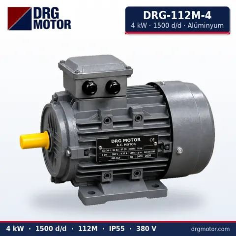
4 kW Three-Phase Motor 1500 rpm – DRG-112M-4 Aluminium
- 4 kW · 1500 rpm (4 poles)
- Aluminium frame · IEC 112M
- Shaft: 28 × 60 mm
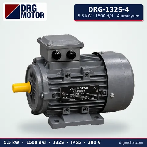
5.5 kW Three-Phase Motor 1500 rpm – DRG-132S-4 Aluminium
- 5.5 kW · 1500 rpm (4 poles)
- Aluminium frame · IEC 132S
- Shaft: 38 × 80 mm
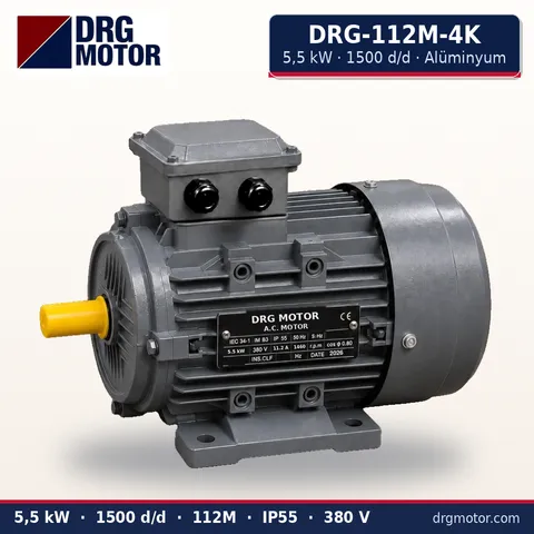
5.5 kW Compact Three-Phase Motor 1500 rpm – DRG-112M-4K Aluminium
- 5.5 kW · 1500 rpm (4 poles)
- Aluminium frame · IEC 112M
- Shaft: 28 × 60 mm
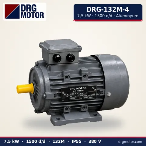
7.5 kW Three-Phase Motor 1500 rpm – DRG-132M-4 Aluminium
- 7.5 kW · 1500 rpm (4 poles)
- Aluminium frame · IEC 132M
- Shaft: 38 × 80 mm
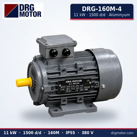
11 kW Three-Phase Motor 1500 rpm – DRG-160M-4 Aluminium
- 11 kW · 1500 rpm (4 poles)
- Aluminium frame · IEC 160M
- Shaft: 42 × 110 mm
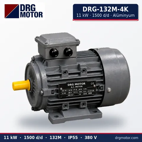
11 kW Compact Three-Phase Motor 1500 rpm – DRG-132M-4K Aluminium
- 11 kW · 1500 rpm (4 poles)
- Aluminium frame · IEC 132M
- Shaft: 38 × 80 mm





