 English
 Le français
 Türkçe

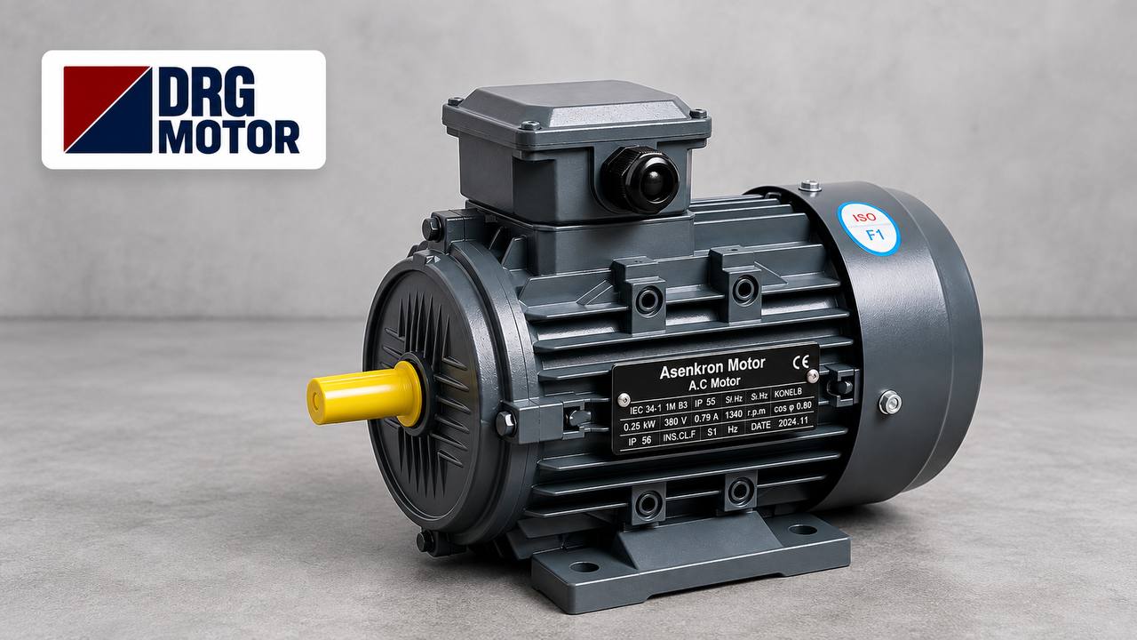

When a new machine arrives at the workshop or the motor of a well pump burns out, the first question is usually “How many kW do I need?” Yet most of the problems we encounter in the field do not come from the wrong power rating; they come from a capacitor arrangement that does not match the load, a flange whose dimensions do not fit, or an undersized cable. We have structured this article to answer, in order, the questions you should ask yourself before buying a single-phase motor.
What Is a Single-Phase Motor and Where Is It Used?
A single-phase induction motor is an electric motor that runs on a single phase and neutral, in other words on the 220–230 V supply found in homes and small businesses. Its main difference from a three-phase motor is that a single phase cannot create a rotating magnetic field on its own. For this reason, single-phase motors have an auxiliary winding next to the main winding and, in most cases, one or two capacitors. The capacitor shifts the phase of the current in the auxiliary winding and allows the motor to start by itself.
The range of applications is wide: booster and circulation pumps, fans and extractors, small conveyors, feed crushers, compressors, woodworking and metalworking machines, and gate and barrier systems are among the most common. If you are looking for a general introduction to the subject, you can also read our article on single-phase electric motors operating on 220 volts.
Know Your Load First: Power and Starting Torque
The first step in choosing the right motor is to understand not the motor but the machine it will drive. Two questions are decisive here: How much power does the machine draw while running, and how hard is it to turn at the very first moment?
On the power side, the value recommended by the machine manufacturer or the kW rating on the existing motor's nameplate is a good starting point. Adding a reasonable margin to the calculated value is a sound approach, but oversizing the motor far beyond what is needed is not a good idea either. A motor running at low load has lower efficiency and power factor, and draws more current than necessary.
In single-phase motors, starting torque is often even more critical than power. Loads such as centrifugal pumps and fans are light at start-up and become harder to drive as speed increases. By contrast, a conveyor with a loaded belt, a compressor starting against back pressure or a crusher full of material demands high torque right from the first moment. A motor with insufficient starting torque either will not turn at all with these loads or will draw high current for a long time and overheat.
Capacitor Motor Types: Which One for Which Application?
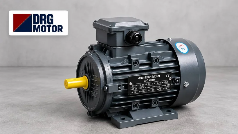
The most important feature that distinguishes single-phase motors from one another is the arrangement they use for starting. The three designs most often encountered in the field are:
Permanent Split Capacitor Motors
In this type, a single run capacitor remains permanently connected to the auxiliary winding. The design is simple, it runs quietly and smoothly, and its power factor is good. Its weak point is low starting torque. That is why it suits fans, extractors, circulation pumps and centrifugal pumps that are light at start-up; it should not be chosen for machines that start under load.
Start-Run (Dual Capacitor) Motors
These motors have two capacitors: one for starting (start) and one for running (run). At start-up both capacitors are in circuit and the motor produces high starting torque. Once the motor reaches a certain speed, a centrifugal switch or an electronic relay disconnects the start capacitor and the motor continues with the run capacitor. This is usually the first choice for heavy-starting applications such as compressors, conveyors, crushers and loaded machine tools.
Auxiliary Winding (Switched Start) Motors
In this design, starting is provided either by the auxiliary winding alone or by a start capacitor connected in series with the auxiliary winding; once the motor has accelerated, a centrifugal switch disconnects the auxiliary winding completely. During operation, however, the motor runs on the main winding only, so its efficiency and power factor are somewhat lower than those of the dual capacitor design. With this type it is important that the switch opens on time; a stuck switch can cause the auxiliary winding to overheat.
Quick decision summary:
- Fan, extractor, circulation pump: permanent split capacitor motor.
- Compressor, loaded conveyor, crusher: start-run motor.
- If you are not sure: consult us and describe how your machine starts.
Choosing the Speed: 1500 or 3000 rpm?
The speed of an induction motor depends on its number of poles. On a 50 Hz supply, the synchronous speed is 3000 rpm for a 2-pole motor, 1500 rpm for a 4-pole motor, 1000 rpm for a 6-pole motor and 750 rpm for an 8-pole motor. The actual speed shown on the nameplate is slightly below these values because of slip; for example, a 4-pole motor runs at around 1400–1450 rpm under load.
Centrifugal pumps and some fans are generally designed for 3000 rpm. In machines driven by belts and pulleys or gearboxes, in conveyors and in machine tools, 1500 rpm motors are more common; at the same power they deliver higher shaft torque and run more quietly. If you are replacing an existing motor, the safest approach is to keep the speed of the old motor. If the speed changes, the pump head, the fan airflow or the operating speed of the machine will change as well.
Mounting Type: B3, B5 and B14
How the motor will be attached to the machine must be clarified before ordering:
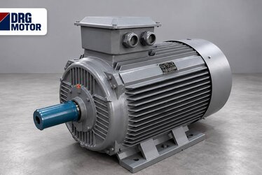
- B3 (foot-mounted): The motor is fixed to a base or frame by the feet on its housing. It is the most common type in belt-and-pulley and coupling applications.
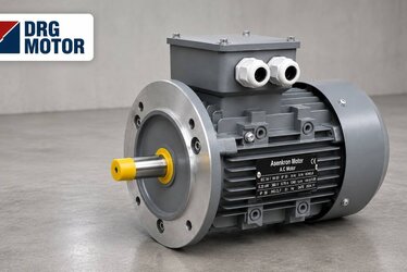
- B5 (large flange): The motor is attached directly to the pump casing, gearbox or machine by a large flange with through holes on the shaft side.
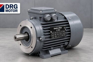
- B14 (small flange): The connection is made through threaded holes on the flange face. Being more compact, it is frequently chosen for small pumps and gearboxes.
- B35 (foot and flange): It has both feet and a flange; it is used in applications where the motor must both sit on a base and be bolted by its flange.
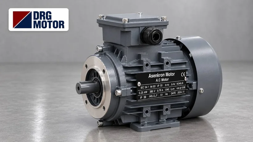
With flange-mounted motors, not only the mounting type but also the flange size, shaft diameter and shaft length must match the existing machine exactly. You can check these dimensions in the drawings of the DRG Motor technical and product catalogue, available through our products page.
Protection Class and Insulation Class
The IP protection class shows how well the motor is protected against dust and water. The first digit refers to protection against solid objects, the second to protection against water. For example, IP54 provides protection against dust deposits and water splashing from any direction, while IP55 provides protection against dust and water jets. This value must be taken into account for motors that will operate outdoors, in a dusty workshop, in an agricultural facility or in areas where washing is carried out.
The insulation class indicates the maximum temperature the winding insulation can withstand. Class B corresponds to a limit temperature of 130 °C and class F to 155 °C. A motor with class F insulation operating with a class B temperature rise provides a significant safety margin in hot environments and under heavy operating conditions. If the ambient temperature is above 40 °C or the motor will operate at an altitude above 1000 metres, it may be necessary to derate the motor or choose the next power size up.
The 220 V Line, Cable Cross-Section and Voltage Drop
A large share of the problems encountered with single-phase motors in the field originates not from the motor but from the supply line. Compared with a three-phase motor of the same power, a single-phase motor draws a higher current through a single line. As a rough calculation, a 2.2 kW single-phase motor draws an operating current of around 13–15 A at 230 V; at start-up this value rises to several times that figure.
On long and thin cables, this current causes a significant voltage drop. The voltage drop on a single-phase line can be estimated with the formula ΔU = 2 × L × I × cosφ / (56 × S) (L: line length in metres; I: current in amperes; S: copper cable cross-section in mm²). For example, for a motor drawing 14 A on a 30-metre line, the drop is about 9.5 V (more than 4%) with a 1.5 mm² cable, whereas with a 2.5 mm² cable it falls to around 5.7 V (about 2.5%).
When the voltage drops, the motor's starting torque decreases in proportion to the square of the voltage. The result is a motor that starts with difficulty, accelerates slowly and overheats. As the line length increases, it is therefore necessary to increase the cable cross-section and to select the fuse and motor protection switch to suit the starting current. We recommend that calculations and work on the electrical installation be carried out by a qualified electrician.
The Power Limit: Where Does Single-Phase End?
In practice, single-phase motors are an efficient and economical solution up to a few kilowatts. The DRG Motor single-phase series is likewise manufactured in the 0.18–3.0 kW power range, with a 220 V supply and speed options from 750 to 3000 rpm. Above this level, the current drawn through a single line reaches values that are difficult to manage on both the cable and the fuse side. In such cases, if a three-phase supply is available, choosing a three-phase motor is the better option. DRG Motor's three-phase range covers 0.25–355 kW in IE3, IE4 and IE5 efficiency classes; you can review all options on our products page.
Reading the Motor Nameplate Correctly
When replacing an existing motor, the most valuable source of information is the old motor's nameplate. The main details to look for on the nameplate are:
- Power (kW or HP): The rated power the motor can deliver at the shaft. 1 HP corresponds to approximately 0.75 kW.
- Voltage and frequency: Usually 220–230 V, 50 Hz for single-phase motors.
- Rated current (A): The basic value for selecting the protection switch and the cable.
- Speed (rpm): Indicates the number of poles and compatibility with the application.
- Capacitor values (µF and V): The capacitance and voltage rating of the run capacitor and, if present, the start capacitor.
- IP class, insulation class and duty type: For example IP55, class F and S1 (continuous duty).
- Frame size and mounting type: For example 90L, B3 or B14; important for mechanical compatibility.
A clear photo of the nameplate and an image showing how the motor is attached to the machine greatly speed up finding the right equivalent.
Common Mistakes in the Field
- Looking only at kW: A permanent split capacitor motor of the same power may not be able to start a loaded conveyor.
- Replacing the capacitor with “something similar”: The new one must have the same µF value and at least the same voltage rating; a weakened capacitor is one of the most common causes of hard starting and humming.
- Running the motor on an extension cord: A thin, long cable lowers the voltage and the motor overheats.
- Blocking the cooling: Pushing the motor against a wall, covering it or running it with a dirty fan cover speeds up overheating.
- Changing the speed: Fitting a 3000 rpm motor in place of a 1500 rpm one changes the operating point of the machine.
A Short Pre-Order Checklist
- What type of load is it, and does it start light or heavy?
- What power and speed are required?
- What is the mounting type (B3, B5, B14, B35), the flange size and the shaft dimensions?
- In what environment will the motor operate, and which IP class is required?
- How long is the supply line, and is the cable cross-section sufficient?
- How many hours a day will the motor run, and how often will it start and stop?
Once this information is clear, the pricing and delivery process also moves faster. For more background, see our article on 220-volt single-phase electric motors, and for price and order requests you can reach us via our contact page.
Frequently Asked Questions
What is the difference between a single-phase and a three-phase motor?
A single-phase motor runs on a 220–230 V supply with one phase and neutral, and needs an auxiliary winding, and in most cases a capacitor, to start. A three-phase motor runs on a 380–400 V three-phase supply, starts by itself and draws a lower line current for the same power. At higher power ratings, a three-phase motor is more efficient and economical.
Up to how many kW can a single-phase motor be used?
In practice, single-phase motors are preferred up to a few kilowatts. The DRG Motor single-phase series covers the 0.18–3.0 kW range. When higher power is required, a three-phase motor is recommended if a three-phase supply is available.
Why might a single-phase motor struggle at start-up?
The most common causes are a capacitor that has lost capacitance, low supply voltage, a thin or long supply cable, the use of a permanent split capacitor motor on a heavy-starting load, and a faulty start switch.
Which single-phase motor is suitable for a pump?
Centrifugal pumps generally run with 3000 rpm motors and present a light load at start-up. If a direct connection to the pump casing is required, B5 or B14 flange-mounted motors are preferred. For pump motors operating outdoors, a high protection class such as IP55 is beneficial.
Let's choose the right single-phase motor together. Send us details of your application, the nameplate data of your old motor or the specifications of your machine, and the DRG Motor team will work with you to determine the motor that suits your needs. You can reach us on +90 (542) 666 11 11 and +90 (533) 777 04 44, send an email to [email protected] or leave a message via our contact page.