 English
 Le français
 Türkçe




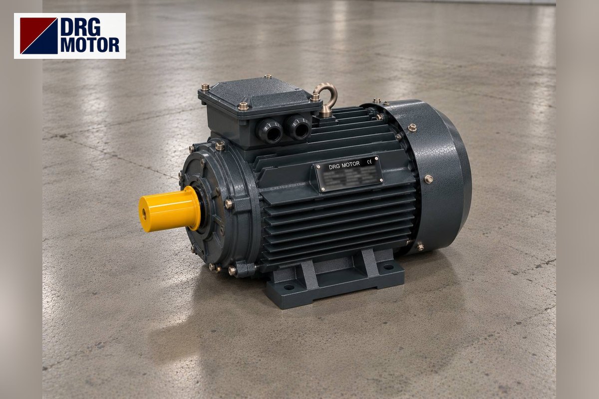

On a stationary silage wrapping machine the electric motor does not turn the bale directly; it drives the gear pump of the hydraulic unit. The wrapping table's hydraulic motor, the bale chamber door, the ejection and tipping cylinders, the film cutter and holder are all fed by this pump. Motor power is set by the pump flow and by the highest-pressure step of the cycle; the power drawn while the table turns is small by comparison.
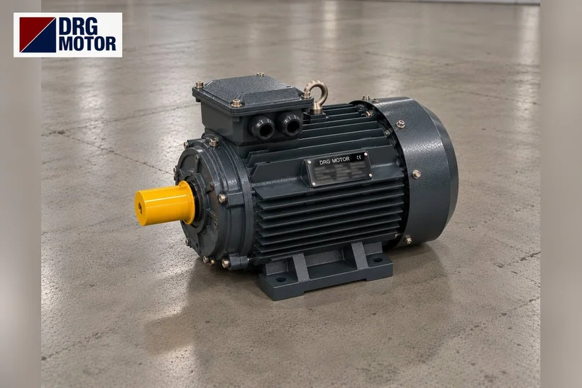
Motor selection therefore starts with the pump displacement and relief valve setting shown on the machine's hydraulic diagram. Most of these units use a 4-pole three-phase motor in cast iron, and the DRG online electric motor shop shows them from the smallest rating upwards. DRG Motor is a manufacturer, supplier and seller of electric motors: pumps, valves and hydraulic motors are outside its range, the standard IEC motor that spins the pump is within it.
The Wrapping Cycle: What Does the Hydraulics Need at Each Step?
Maize silage or cut grass fills the bale chamber via a feed belt. On combined (baling + wrapping) machines, rollers or chain-and-slat elements inside the chamber turn and compress the material; once the bale reaches the required density, net or twine is applied, the chamber door is opened by a hydraulic cylinder and the bale is transferred to the wrapping table. On wrap-only machines the bale is placed on the table by a loader or loading arm.
The wrapping table turns the bale on two axes: the table rotates about a vertical axis while its rollers roll the bale about its own axis. Two rollers of different diameter in the pre-stretcher stretch the film before it reaches the bale; when the set number of turns is complete, the cutter cuts the film, the holder grips the end and the tipping cylinder drops the bale to the ground.
Hydraulically the cycle has two characters. Table rotation is a long but medium-pressure task. Closing the door, compressing and tipping the bale are high-pressure peaks lasting a few seconds. During these peaks the motor can go above its rated torque; selection is based on the peak pressure.
From Pump Flow and Pressure to Motor Power
Hydraulic power follows from P = Q·p/(600·η), taking Q in l/min, p in bar and giving P in kW. The calculation below is an example with assumptions; the real figure is on the machine's hydraulic diagram and the builder's nameplate.
Example: a 14 cm³/rev gear pump, motor at 1460 rpm, assumed pump volumetric efficiency 0.95 and overall efficiency 0.85, gives a flow of ≈ 14·1460/1000·0.95 ≈ 19.4 l/min.
| Cycle step | Example pressure | Power needed (example) | Duration |
|---|---|---|---|
| Table and roller rotation | 90 bar | ≈ 3.43 kW | Long, every bale |
| Door, ejection arm | 140 bar | ≈ 5.33 kW | A few seconds |
| Compression, tipping peak | 180 bar | ≈ 6.85 kW | Short peak |
Here a DRG-132M-4 (7.5 kW, 1460 rpm, 49.1 Nm) covers the peak step below its rated power. The 5.5 kW DRG-132S-4 runs comfortably up to 140 bar; at the 180 bar peak the motor exceeds its rated torque. With a breakdown torque ratio of 2.3 the motor gets through a short peak, but if the cycle repeats often the winding heats up and the overload trips. If the relief valve has been set higher, redo the calculation at that pressure.
Converting from a Tractor Pump to an Electric Unit
When PTO-driven machines are converted to an electric unit, pump speed changes. Example: assuming a 540 rpm PTO and a 1:3.5 speed-up gearbox, the pump turns at about 1890 rpm; if the same pump is coupled directly to a 1460 rpm motor, flow drops to about 0.77 times and the table slows down. Keeping the old table speed needs a larger-displacement pump, which raises motor power by the same ratio.
Click to see current electric motor prices and order nowSEE PRICES →
Connecting the Motor to the Pump: Bell Housing, Coupling and Flange
On hydraulic units the motor usually sits vertically or horizontally with a B5 flange on the pump bell housing, with a gear or flexible coupling between pump shaft and motor shaft. When replacing, the bell housing flange must match the motor flange. B5 flange dimensions from the DRG catalogue:
- Frame 112M: flange outer diameter 250 mm, bolt circle 215 mm, spigot 180 mm, shaft 28×60 mm.
- Frames 132S/132M: flange Ø 300 mm, holes on Ø 265 mm, spigot Ø 230 mm, shaft 38×80 mm.
- Frame 160M: flange outer diameter 350 mm, bolt circle 300 mm, spigot 250 mm, shaft 42×110 mm.
If a motor with a different shaft length is fitted, the coupling hub does not seat correctly and the pump seal takes axial load. For a small-flange (B14) connection, dimensions are confirmed at order. Further hydraulic-unit configurations are covered under hydraulic power unit electric motors.
Open Yard, Dust, Silage Effluent and Winter
Stationary wrappers often work next to the silage clamp, in an open yard or under a half-open shed. Dry hay season brings heavy dust, maize silage brings acidic effluent and moisture. IP55 protection is adequate against dust and splashing water; still, the motor should not stand uncovered in the rain, silage juice must not drip onto it, and the fan cowl must not clog with dry hay fragments.
The motors' operating range is −15 °C to +40 °C. On a winter morning cold hydraulic oil thickens; the pump needs more torque in the first minutes and starting takes longer. Running the unit unloaded to warm the oil before the first bale protects the motor. If the loader is washed next to the machine, keep the motor away from the pressure jet.
Starting Current, Long Cables and Generators
The cable between the farm switchboard and the machine is often long. A DRG-132M-4 takes 14.3 A on 400 V and its inrush is 7.5 times that, so a direct-on-line start approaches 107 A. Star-delta starting cuts this to about one third, but starting torque also falls to one third, so the pump should start unloaded (unloading valve open). Check the cable size for the run length with the motor cable size calculator.
On farms with a weak supply or a generator, generator capacity must be large enough to handle the motor's starting current. From 4 kW the DRG winding is 400/690 V: delta on the farm's 400 V network, which allows star-delta starting.
Preparing for Replacement and a Quote
- Pump displacement (cm³/rev) and relief valve pressure from the hydraulic diagram.
- Old motor nameplate: power, speed, voltage and connection (Y or Δ).
- Mounting form (B5, B3 or B35) and the three bell-housing flange dimensions: outer Ø, hole circle Ø, spigot Ø.
- Shaft size, coupling type; whether the motor stands vertical or horizontal.
- Whether the machine is combined (baling + wrapping) or wrap-only; bales wrapped per hour.
- Cable length from switchboard to machine, starting method and generator capacity if any.
Augers, elevators and feed mixers on the same farm are dealt with under agricultural machine electric motors.
Which DRG Motor for a Silage Wrapper Hydraulic Unit?
On units working in an open yard the rugged cast iron frame stands out; the 4-pole models below cover the range from wrap-only machines to combined baler-wrapper units.
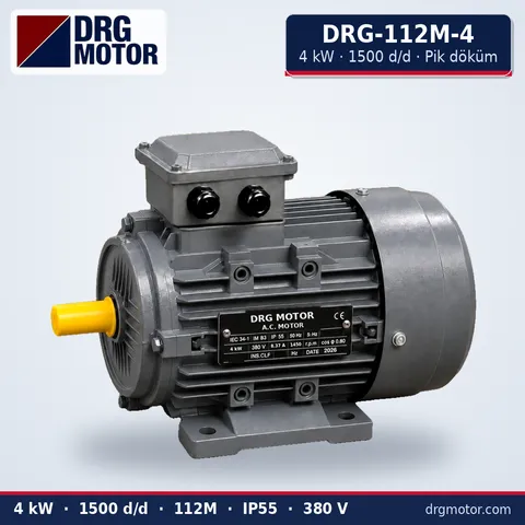
4 kW Three-Phase Motor 1500 rpm – DRG-112M-4 Cast Iron
- 4 kW · 1500 rpm (4 poles)
- Cast iron frame · IEC 112M
- Mounting: B3 · B5 · B14 · B35
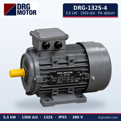
5.5 kW Three-Phase Motor 1500 rpm – DRG-132S-4 Cast Iron
- 5.5 kW · 1500 rpm (4 poles)
- Cast iron frame · IEC 132S
- Mounting: B3 · B5 · B14 · B35
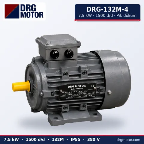
7.5 kW Three-Phase Motor 1500 rpm – DRG-132M-4 Cast Iron
- 7.5 kW · 1500 rpm (4 poles)
- Cast iron frame · IEC 132M
- Mounting: B3 · B5 · B14 · B35
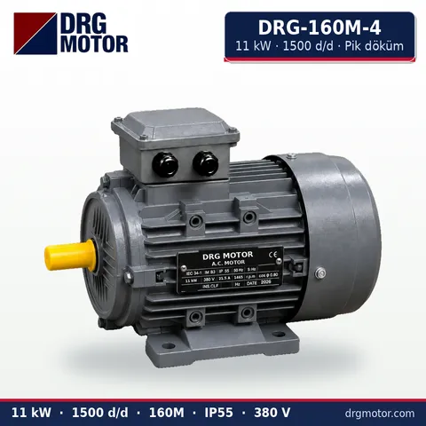
11 kW Three-Phase Motor 1500 rpm – DRG-160M-4 Cast Iron
- 11 kW · 1500 rpm (4 poles)
- Cast iron frame · IEC 160M
- Mounting: B3 · B5 · B14 · B35
Click to see current prices and order these motors nowSEE PRICES →
Silage Wrapping Machine Motor: Questions
What kW motor does a silage wrapping machine need?
It depends on the machine type and its pump. Small wrap-only machines use a few kW, combined baler-wrappers use larger motors. The exact figure is on the builder's nameplate and hydraulic diagram; it can be calculated from pump displacement and the highest pressure.
Why does the wrapper motor struggle when the bale is tipped?
Tipping and compression are the highest-pressure parts of the cycle. If the relief valve is set higher than needed or the pump has been enlarged, the motor goes above its rated power at this step. Measure the pressure with a gauge and check the motor current at that moment.
Can I convert a tractor-driven wrapper to an electric motor?
In most cases yes; either the pump is coupled to the motor instead of the PTO, or a separate hydraulic unit is added to the machine. Since pump speed changes, flow and table speed must be recalculated and motor power chosen for the new pump displacement.
How do I protect a wrapper motor that stands outdoors?
Protect the motor from rain with a canopy above it, do not block the fan air inlet, and stop silage effluent running onto it. At the start of winter and of the season, check the terminal box gasket and the cable gland.
A plate photo of the present motor, the pump displacement, the bell-housing flange and the shaft size are enough to target the motor for your unit: send them on WhatsApp or put the models in your quote list. We also answer on +90 (542) 666 11 11, at info@drgmotor.com and through the contact form. Aluminium and cast iron 4-pole versions are gathered in the DRG online shop.





