 English
 Le français
 Türkçe




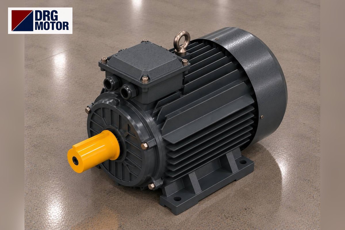

A rotary valve (rotary airlock, cell wheel) motor turns a rotor divided into pockets inside a housing, through a gearbox, slowly, often somewhere between single-digit and a few dozen rpm. Each turn passes the volume carried by the pockets, so the dosing rate is set not by the motor itself but by the gear ratio and, where needed, by rotor speed adjusted with an inverter. Power demand is often below 1 kW; what needs real attention is the gearbox connection, protection against jamming and the dust in the area.
DRG Motor is a manufacturer, supplier and seller of electric motors. The rotary valve’s gearbox is not part of the supply; DRG provides the three-phase asynchronous IEC motor connected to the gearbox input; the small aluminium-frame versions can be browsed in the buy electric motors online section.
A Rotary Valve Does Two Jobs: Feeding and Sealing Air
The rotor vanes sit in the housing with a very small clearance. Material from the hopper or cyclone above fills the pocket facing up; as the rotor turns, the pocket moves down and empties. The valve thus meters the material while holding the pressure difference between top and bottom.
This second task is why it is called an airlock. Under a cyclone or bag filter, the valve stops outside air leaking into the chamber under suction; at the start of a pneumatic conveying line it stops compressed air escaping back into the hopper. As vane tips wear and clearance grows, leakage rises and dosing drifts.
Mind the similar name: the plug or “cell type” fan in air handling units is a different machine; its motor selection is described on the plug fan and plenum fan motor page.
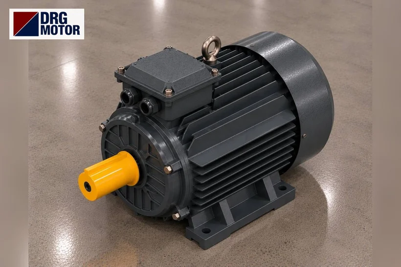
Dosing Rate: Pocket Volume × Fill × Rotor Speed
A rotary valve’s throughput is roughly the product of pocket volume per turn, pocket fill ratio and rotor speed. Fill depends on how freely the material flows and on rotor speed: the faster the rotor, the less time the pockets have to fill. Valve makers therefore give a recommended rotor speed range for each valve size; the exact value is in the valve catalogue.
Example (assumptions): pocket volume 5 l/rev, fill 0.7, motor DRG-802-4 (1420 rpm) and gear ratio 70. The rotor turns at 1420 / 70 ≈ 20.3 rpm and throughput is about 71 l/min, i.e. 4.26 m³/h. If you vary dosing with an inverter, rotor speed and throughput fall in proportion to frequency:
| Frequency | Motor speed (approx.) | Rotor speed | Throughput (example) |
|---|---|---|---|
| 50 Hz | 1420 rpm | 20.3 rpm | 71 l/min |
| 40 Hz | 1136 rpm | 16.2 rpm | 57 l/min |
| 30 Hz | 852 rpm | 12.2 rpm | 43 l/min |
| 20 Hz | 568 rpm | 8.1 rpm | 28 l/min |
An induction motor’s own fan is fixed to the shaft. As frequency drops, cooling air drops too; if the valve will run near 20 Hz all the time, monitor motor temperature or choose a gear ratio that puts normal dosing around 40–50 Hz. DRG does not sell inverters; it supplies the motor that the inverter drives.
Click to see current electric motor prices and order nowSEE PRICES →
Gearbox and Motor: Where the Torque Comes From
The rotor needs high torque at low speed. A small 4-pole motor with a worm or helical gearbox covers this. The DRG-802-4 in the example delivers 5.04 Nm rated torque; with a ratio of 70 and a worm gearbox assumed to pass on 70 percent of the input (factor 0.7), about 247 Nm is available at the rotor shaft.
Whether that much torque is needed depends on rotor diameter, seal friction and how sticky the material is. With sticky, damp or fibrous material, pieces trapped between vane and housing momentarily raise torque. That is why even a small rotary valve may take 0.55 or 0.75 kW instead of 0.37 kW; the decision should follow the power given by the valve manufacturer.
The motor is usually flange-connected to the gearbox. The DRG catalogue lists these B5 values: frame 71 has pitch circle M 130, spigot N 110, shaft 14 × 30 mm; frame 80 has M 165, N 130, shaft 19 × 40 mm; frame 90S has M 165, N 130, shaft 24 × 50 mm. If the gearbox takes a B14 (small) flange, its size must be confirmed at the order stage.
Jamming, Reversing and Motor Protection
The most frequent rotary valve fault is the rotor locking on a foreign object (a bolt, weld spatter, a hardened lump). When locked, the motor draws a current close to starting current: for the DRG-802-4 rated current at 400 V is 1.75 A and Is/In is 6.6, so about 11.6 A with a locked rotor. The overload relay must see this quickly and open the circuit.
On small motors it matters to set the overload close to the nameplate current; leaving it high endangers the gearbox and rotor vanes rather than the motor. To size the overload relay and contactor, use the motor overload, fuse and contactor selection page. Some plants also fit a rotation sensor on the rotor shaft; if the valve stops while feed continues, the system raises an alarm.
Some systems apply a short reverse rotation to clear a jam. Reversing is done by swapping two of the three phases with a contactor or inverter panel; no change to the motor itself is needed.
Dusty and Explosive Dust Areas
A rotary valve is almost always in a dusty place: flour, sugar, starch, cement, lime, coal dust, plastic granules. With IP55, any dust that gets into a DRG motor stays too little to form harmful deposits. Dust building up on the frame fins reduces cooling, so regular cleaning is needed.
In areas classified as explosive atmosphere zones because of combustible dusts such as flour, sugar, starch or coal, a standard IEC motor cannot be used; the only answer there is an Ex-protected special motor, which DRG’s standard range does not cover. If the valve is driven from outside the zone, for example through a wall with an extended shaft, the case must be assessed against the plant’s zone classification.
On valves carrying hot material from a dryer or kiln, the motor frame can heat up. Ambient temperature at the motor must not exceed +40 °C; leave enough air flow between gearbox and motor.
Information to Collect Before Replacing the Motor
- Power, speed, voltage and current on the motor nameplate
- Gearbox type (worm, helical) and the ratio on its nameplate
- Mounting: B5 large flange, B14 small flange or foot
- Shaft diameter and length, key width
- The rotor speed the valve runs at and the inverter frequency range
- Whether the area is an explosive dust zone
- Overload setting and whether reversing is used
DRG Motors for Rotary Valves and Airlocks
Small light aluminium-frame 4-pole models (about 1400 rpm) for flange connection to the gearbox input; chosen by the power given by the valve maker and the gearbox flange.
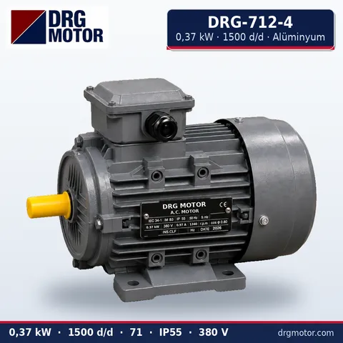
0.37 kW Three-Phase Motor 1500 rpm – DRG-712-4 Aluminium
- 0.37 kW · 1500 rpm (4 poles)
- Aluminium frame · IEC 71
- Mounting: B3 · B5 · B14 · B35
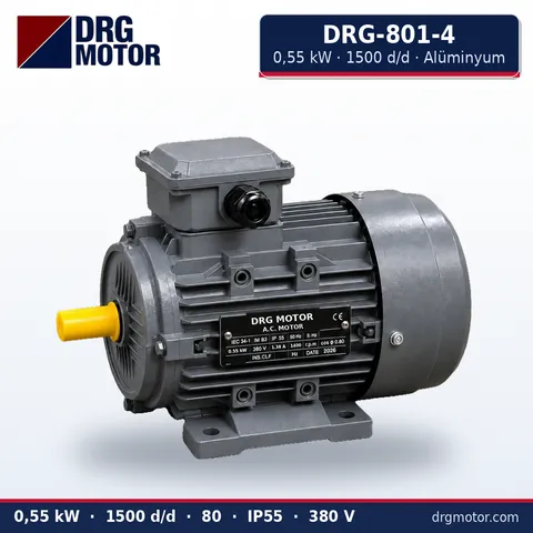
0.55 kW Three-Phase Motor 1500 rpm – DRG-801-4 Aluminium
- 0.55 kW · 1500 rpm (4 poles)
- Aluminium frame · IEC 80
- Mounting: B3 · B5 · B14 · B35
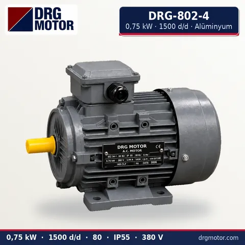
0.75 kW Three-Phase Motor 1500 rpm – DRG-802-4 Aluminium
- 0.75 kW · 1500 rpm (4 poles)
- Aluminium frame · IEC 80
- Mounting: B3 · B5 · B14 · B35
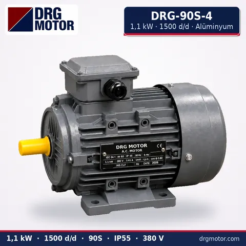
1.1 kW Three-Phase Motor 1500 rpm – DRG-90S-4 Aluminium
- 1.1 kW · 1500 rpm (4 poles)
- Aluminium frame · IEC 90S
- Mounting: B3 · B5 · B14 · B35
Click to see current prices and order these motors nowSEE PRICES →
Rotary Valve Motor: Frequently Asked Questions
How many kW does a rotary airlock drive need?
It depends on valve size, material and pressure difference. Small airlocks often use 0.37–0.75 kW, larger valves more. The exact value is in the valve maker’s catalogue and on the existing motor nameplate.
How do I reduce rotary valve speed?
Either increase the gear ratio or drive the motor at a lower frequency with an inverter. At very low frequency motor cooling drops; if long-term low speed is needed, changing the ratio is the sounder option.
Why does the airlock motor keep tripping?
Usually a rotor vane is rubbing the housing, material has stuck to the rotor, or a foreign object is jammed. Do not upsize the motor first: with the supply locked out, rotate the rotor manually and feel for rubbing.
Can a standard motor go on a rotary valve in a flour mill?
Not in an area classified as an explosive dust zone: only an Ex-protected special motor fits there. Outside classified areas, a standard IP55 motor can be used.
For a quote, write to us via WhatsApp with a photo of the motor nameplate, the gearbox type and ratio, the flange size (B5 or B14), the shaft size and the valve’s environment, or add the models to the quote list. You can also call +90 (542) 666 11 11, write to info@drgmotor.com or use the contact page. Motors for worm gearboxes are on the worm gearbox electric motor page; the full range is in the online store.





