 English
 Le français
 Türkçe





A farm manure separator splits slurry into a solid fibre fraction and a liquid fraction by pressing it with an auger screw that turns inside a fine-slotted screen cylinder. Because the screw runs at just a few dozen rpm, the motor is connected through a gearbox rather than directly. Selection is governed by the torque the screw needs at the gearbox output; the kW figure is a result of that torque and the screw speed.
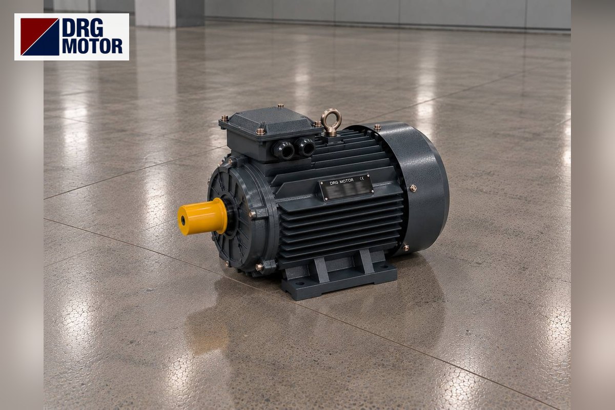
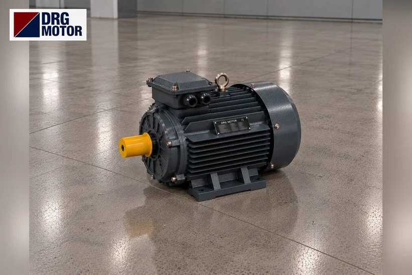
A typical drive pairs a three-phase motor of a few kW, 4-pole or 6-pole, with a helical or bevel-helical gearbox. Of that pair, the motor is DRG's part: DRG Motor is a manufacturer, supplier and seller of electric motors, while the gearbox and feed pump come from the machine builder or a gearbox supplier. Cast iron models suited to wet, ammonia-laden environments are in the DRG online electric motor shop.
How Does a Screw Press Separator Work?
Slurry from the barn channel or a reception pit is pumped into the separator's inlet hopper. Inside a horizontal screen cylinder an auger turns with its outer diameter very close to the screen. As the screw carries material towards the outlet, liquid drains through the screen slots into the collecting trough below.
At the outlet there is a flap (plug) loaded by springs or weights. The fibrous cake cannot leave until it builds enough pressure to push this flap open; this creates compaction in the last section of the screw, and cake dryness is set by the flap load. Tightening the flap gives a drier cake, but it also raises torque on the screw shaft and motor current. The solid fraction is used as bedding or compost, the liquid fraction is pumped to a lagoon or the fields.
This machine is different from both a manure scraper and a manure granulation plant. A scraper pulls a blade back and forth along a channel; its motor selection is on the barn manure scraper motors page. The separator's load is the compaction torque of a screw turning in place.
Low Screw Speed, High Torque: Worked Example
Exact screw speed and torque come from the separator builder's documents. The rows in the table describe one scenario only: a screw expected to turn at roughly 35 rpm, with gearbox losses covered by a 0.95 factor.
| Motor | Gear ratio | Screw speed | Output torque (rated) |
|---|---|---|---|
| 3 kW, 4-pole (DRG-100L2-4) | i = 40 | ≈ 36.3 rpm | ≈ 752 Nm |
| 5.5 kW, 4-pole (DRG-132S-4) | i = 40 | ≈ 36.5 rpm | ≈ 1368 Nm |
| 4 kW, 6-pole (DRG-132M1-6) | i = 28 | ≈ 34.6 rpm | ≈ 1051 Nm |
| 5.5 kW, 6-pole (DRG-132M2-6) | i = 28 | ≈ 34.6 rpm | ≈ 1444 Nm |
Calculation: n2 = n1/i and T2 = Tn·i·0.95. For the 132S-4, for instance, 36.0 Nm × 40 × 0.95 ≈ 1368 Nm. This motor's Ts/Tn is 2.0, so a direct-on-line start briefly loads the gearbox output with roughly 2736 Nm. If the gearbox's permitted output torque is below that, rather than enlarging the motor, review the gearbox together with a starting method that limits starting torque. Enter the ratio of your gearbox in the gearbox output speed and torque calculator to see screw speed and torque.
4-Pole or 6-Pole?
The same screw speed is reached with a ratio of about 1:42 from a 4-pole motor and about 1:28 from a 6-pole motor. With 6 poles the gear ratio is smaller and motor torque is higher at the same power; on the other hand the frame is one size larger. If the existing gearbox stays, you must keep the old motor's pole number; otherwise screw speed changes and separation quality suffers.
Click to see current electric motor prices and order nowSEE PRICES →
Dimensions to Check at the Gearbox Input
On most newer separators the motor sits directly (B5) on the IEC flange at the gearbox input; older belt-driven machines carry a foot-mounted (B3) motor on a tensioning slide. With a flange connection, the gearbox side and the motor side must match exactly. Catalogue values for the frames in the table:
- 100L (3 kW 4-pole): P = 250, M = 215, N = 180 mm; shaft Ø28, length 60 mm, key 8 mm.
- 132S and 132M (5.5 kW 4-pole, 4 and 5.5 kW 6-pole): P = 300, M = 265, N = 230 mm; shaft Ø38, length 80 mm, key 10 mm.
P is the flange's outside diameter, M the circle carrying the fixing holes, N the centring shoulder that enters the gearbox.
At the same kW rating, 4- and 6-pole motors may have different frames: the 4 kW 6-pole motor is frame 132M, while the 4 kW 4-pole motor is 112M. The gearbox input flange will not absorb that difference. If the gearbox input takes a small B14 flange, we verify the dimensions together at the order stage. For gearboxes with a helical input stage, see electric motors for helical gearboxes.
Protecting the Motor in a Wet, Ammonia-Laden Environment
The separator usually stands above the slurry pit, on a platform or concrete plinth. The air carries ammonia and hydrogen sulphide, humidity is constant, slurry splashes and winter brings frost. These conditions corrode metal surfaces and terminal connections; a painted cast iron frame withstands mechanical knocks better than aluminium.
IP55 copes with splashes, yet the motor must never stand in slurry or be hosed down. Mounting the motor horizontally with the cable entry facing down, keeping the terminal box gasket sound and bringing the cable in with a drip loop from below stops water tracking inside. If the motor would sit inside an enclosed pit where gas collects, or in the explosive zone of a biogas line, a standard IEC motor cannot be used there; that location needs an Ex-protected special motor. On an open platform the −15 °C to +40 °C ambient range applies; where frost is severe, a canopy over the motor is enough.
Load Swings, Blockage and Protection
The dry-matter content of slurry changes during the day; a mix containing feed residue, straw or sand loads the screw suddenly. If the feed pump stops and the separator runs empty, torque drops, and current rises when it reloads. If the screen clogs, the screw jams behind the cake and the motor stays above rated current for a long time.
- Adjust the overload relay to the plate current and no further — for a DRG-132S-4 that means 10.7 A on 400 V.
- Measure motor current whenever the flap load is increased; if it exceeds the rated value, back off the load.
- After a long stop, cake dried inside the screw makes the first start harder; a short flush with clean water before stopping protects the motor.
- Some control panels briefly reverse the screw when current rises to clear a blockage. In that case check that motor and gearbox are suitable for reversing and that the contactors are electrically interlocked.
Before Replacing the Motor or Ordering
- What the old motor's plate says about kW, rpm, poles and voltage.
- Gearbox nameplate: type (helical, bevel-helical, worm), ratio and input flange size.
- Mounting (B5, B3 or B35), shaft diameter and length, key size.
- Screw speed (counted at the output shaft) and the separator's hourly throughput.
- Environment: above the pit or in a closed room; any risk of gas build-up.
- Starting method and whether reversing is used to clear blockages.
DRG Motors Suited to Manure Separator Drives
Cast iron models were chosen for the wet, ammonia-laden environment; the 4- and 6-pole options can be matched to the existing gear ratio to give the same screw speed.
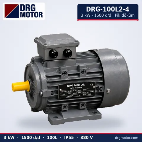
3 kW Three-Phase Motor 1500 rpm – DRG-100L2-4 Cast Iron
- 3 kW · 1500 rpm (4 poles)
- Cast iron frame · IEC 100L
- Mounting: B3 · B5 · B14 · B35
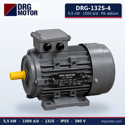
5.5 kW Three-Phase Motor 1500 rpm – DRG-132S-4 Cast Iron
- 5.5 kW · 1500 rpm (4 poles)
- Cast iron frame · IEC 132S
- Mounting: B3 · B5 · B14 · B35
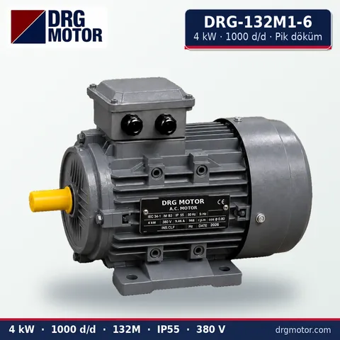
4 kW Three-Phase Motor 1000 rpm – DRG-132M1-6 Cast Iron
- 4 kW · 1000 rpm (6 poles)
- Cast iron frame · IEC 132M
- Mounting: B3 · B5 · B14 · B35
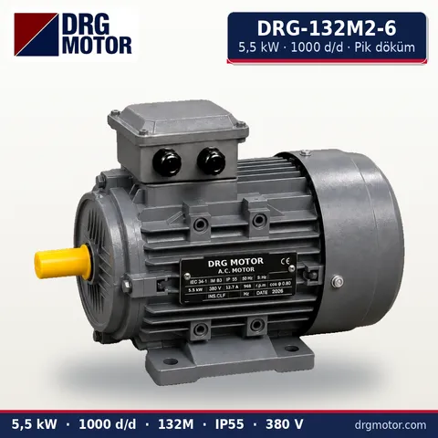
5.5 kW Three-Phase Motor 1000 rpm – DRG-132M2-6 Cast Iron
- 5.5 kW · 1000 rpm (6 poles)
- Cast iron frame · IEC 132M
- Mounting: B3 · B5 · B14 · B35
Click to see current prices and order these motors nowSEE PRICES →
Questions About Manure Separator Motors
How many kW does a manure separator motor need?
It depends on the screw diameter, throughput and flap load. Farm-size machines commonly use motors of a few kW; the binding figure is printed on the separator's own plate. Motor power is calculated from the torque the screw needs at the gearbox output and from the screw speed.
The separator motor keeps tripping: what should I check?
First check the flap load and whether the screen slots are blocked. Then measure the slurry's dry-matter content, the feed rate and the motor current. If current returns to normal when the flap is eased, the problem is the setting, not the motor.
Can a 6-pole motor be fitted to a separator?
Yes, but the gear ratio must suit it. If the existing gearbox was selected for a 4-pole motor, a 6-pole motor turns the screw about one third slower and throughput drops. Frame size and flange dimensions may change too.
Does a manure separator need a frequency inverter?
Not necessarily; many separators run at fixed speed. An inverter can be used to adjust screw speed for different manure types; because the cooling fan sits on the motor shaft, its airflow falls with speed, so running for hours far below base speed should be avoided. DRG does not sell inverters.
Photos of the motor plate and gearbox plate, whether the motor is flange- or foot-mounted, its shaft diameter and the screw speed counted at the output shaft give us a good starting point. Drop these on WhatsApp or put the models you picked into the quote list; +90 (542) 666 11 11, info@drgmotor.com and the contact page are open as well. Every power class that suits a separator can be seen in the DRG online shop.





